

 PDF
PDF ePub
ePub Citation
 Print
Print


I. Introduction
The implant is designed to be connected to the inside of the human body and supported by alveolar bone. Since the implant should be maintained through adherence to bone, having it surrounded by healthy bone tissues is crucial.
In particular, the implant does not have periodontal ligament unlike natural teeth, and the stress exerted on it from the outside may have different distribution pattern than that applied to natural teeth. Moreover, if the tissues surrounding the implant are inflamed, the inflammation spreads fast to the subsystem, and such is more likely to cause bone loss1.
Therefore, it is very important that healthy bone tissues exist around the implant to ensure long-term maintenance. Nonetheless, there may be several unfavorable conditions that cause bone loss around the implant. There are many theories as to the reason implant cervical bone is absorbed and lost. Some of the factors considered include1: damage incurred during surgery2; overload generated by excessive occlusion3; inflammation around the implant4; small gaps between the fixture and abutment5; shaking caused by poor fixing of abutment6; biological width7, and; design of the implant neck8,9 either separately or in combination.
Previously considered the standard, the Branemark implant is known for its high rate of implant cervical bone absorption since it has all of the abovementioned factors. Thus, recently developed implant materials have stronger connection between the fixture and abutment to reduce shaking and minimize the stress exerted on the implant cervical bone.
The following are the ways of reducing the stress exerted on the cervical bone around an implant: increasing the number of implants used; using implants with larger diameters; improving the implant abutment design; improving the implant neck thread design, and; increasing the contact area between the implant and bone by expanding the implant surface area.
If the changes made to the implant neck to reduce the stress exerted on the cervical bone around the implant actually have an adverse effect on implant stability or biological width, the neck form should be improved to avoid such risks and contribute to bone formation.
In this study, the distribution of stress exerted on the bone and the degree of bone formation facilitation were observed when implants with wing-shaped protrusions in the neck were used.
II. Materials and Methods
1. Implant design
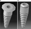
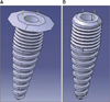
To reduce the stress exerted on the cervical bone around the implant, a wide bevel-type implant with protrusions on the cervical area was designed. Its plan was created with CATIA V5 (APuser, Seoul, Korea), a three-dimensional design program.(Figs. 1, 2)
1) Three dimensional (3D) structural design was done based on the drawing to analyze the structure of 2 types of implant structures presented.
2) Type 1 (wide bevel-type implant): submerged Implant wide bevel-type (IS3010WB)
Type 2 (general root-type implant): submerged implant general type (IS3010G)
- As shown in Fig. 1, the 3D design program CATIA V5 was used to execute the design in Fig. 2 based on a computer aided design drawing.
3) IS3010WB/IS3010G designed with CATIA V5 was manufactured with titanium, and CATIA V5 was used for structural interpretation to apply the mechanical material properties of titanium. The material properties applied are shown in Table 1.
4) After applying material properties, mesh work was done in the general structure for structural interpretation.
5) After the mesh work, forces of 30 N/m2, 35 N/m2, 40 N/m2, and 45 N/m2 were exerted on the implant, and static analysis was performed during the use of finite element method (FEM).
The force exerted was vertical (Z axis) as shown in Fig. 3 from above the implant (indicated by the yellow arrow); both pressure and tension were exerted, and displacement was measured accordingly.
III. Results
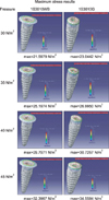
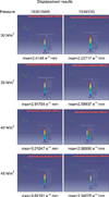
Each implant received force of 30 N/m2, 35 N/m2, 40 N/m2, and 45 N/m2. The results of such application of force on 2 types of implants are shown in Figs. 4-6.
When maximum stress was applied, the structural displacement made to 2 types of implants (Fig. 4) caused almost no change to the upper structure of the wide bevel-type implant as stress increased (30 N/m2, 35 N/m2, 40 N/m2, and 45 N/m2) as well as evident gradual deformation on the tapped part of the general root-type implant.
When maximum stress was applied, the maximum forces measured at the mesh were 21.5979 N/m2, 25.1974 N/m2, 29.7971 N/m2, and 32.3967 N/m2 for the wide bevel-type implant and 23.0442 N/m2, 26.9950 N/m2, 30.7257 N/m2, and 34.5584 N/m2 for the general root-type implant in response to stress of 30 N/m2, 35 N/m2, 40 N/m2, and 45 N/m2.
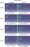
The forces measured when tension was exerted were 6.7952 N/m2, 7.9161 N/m2, 9.0470 N/m2, and 10.1779 N/m2 for the wide bevel-type implant and 21.4053 N/m2, 24.9729 N/m2, 29.5404 N/m2, and 32.1090 N/m2 for the general root-type implant.
The forces measured when stress was exerted were 2.4246 e-10 mm, 2.9170 e-10 mm, 3.2195 e-10 mm, and 3.6219 e-10 mm for the wide bevel-type implant and 2.2272 e-10 mm, 2.5994 e-10 mm, 2.9696 e-10 mm, and 3.3408 e-10 mm for the general root-type implant.
As shown in the result above, the wide bevel-type distributes average pressure of 2 N/m2 better than the general root-type does.
This implies that the wide bevel-type implant (IS3010WB) distributes pressure to the Z axis from the upper structure more effectively than the general root-type implant (IS3010G) does.
In addition, the result concerning tension (Fig. 5) shows that the wide bevel-type implant distributes pressure three times better than its counterpart with far better structure stability.
In terms of displacement, Fig. 6 presents the structural changes in response to pressure in length. Note, however, that this figure is too small to show displacement smaller than e-10 mm; thus, the difference was not significant.
The overall result suggests that the wide bevel-type implant is far better than the general root-type implant in terms of pressure distribution.
IV. Discussion
Continuous efforts are being made to ensure stability in the cervical bone after implanting. To do so, the surface shape of the implant is changed to reduce the time needed for integration to bone, bonded bone strength is increased for greater stability, fine thread is made in the implant neck to minimize bone loss, and one-body implant is made to prevent the shaking of the abutment or increase biological width. In many cases, the implant neck is designed differently to transfer stress most efficiently.
Chung et al.1 observed the change of stress exerted on the cervical bone with FEM with two types of implants - Nobel Biocare's NobelDirect and Straumann's ITI - which had a straight form among other one-body implants. The result suggests that the stress exerted is reduced if the neck penetrating is curved rather than straight.
Bozkaya et al.10 used 5 types of widely used implants (Ankylos, Astra, Bicon, ITI, and Nobel Biocare) for analysis based on FEM and observed the force transferred to the surrounding bone when occlusive force was exerted. They exerted overload for vertical, lateral, and shearing forces and in the general occlusive direction (11.3°; occlusion to 1 mm from the central axis of the implant) to see which type of implant delivered the highest overload to the surrounding bone. The result showed that ITI was the one that transferred most stress to the surrounding bone. This test also suggested that various types of forces exerted on the implant were mostly delivered to the bone surrounding the implant neck.
According to Geng et al.11, the factors affecting the mechanism delivering force to the interface between the alveolar bone and implant included the type of force, material properties of the implant and prosthetic appliance, shape of the implant, and structure of the surface, among others.
Their study found that the layered structure delivered force in a more uniform manner compared to the straight, cylindrical design. In particular, such requirements were deemed to have been met by changing the size, shape, material, and surface of the implants, and some of them were developed prior to fundamental research12.
Abu-Hammad et al.13 made implant surfaces whose cross section was smooth or spiral- or star-shaped and analyzed the stress exerted by such implants on the surrounding bone. According to them, the implant with no change made to the surface exerted the least stress. Personally, however, the authors believe that this maximizes friction against surrounding bone, and that it is impossible to use in actual cases.
Today's implant neck designs are in many ways significant and are studied from the esthetic or stability point of view. In particular, Bischof et al.14 used ITI implants of the same properties with 4.8 mm and 6.5 mm neck for a comparative analysis. The wider one reportedly causes less bone loss.
In this study, too, we widened the implant neck for better stress distribution. The wide bevel-type neck design in particular minimizes the displacement of the implant itself and the stress exerted by the displacement force on the surrounding bone when implanted. This is a very important point, indicating that the local stress exerted on the interface between the implant and bone is related to bone loss.
Moreover, the protrusions in the neck act as an umbrella that prevents the soft body in the bottom from growing upward and facilitates bone formation at the bottom. Even though the implant is in contact with poor-quality bone in the implanting procedure, it is considered to contribute to the success rate of the procedure since bone formation is facilitated from the bottom.
V. Conclusion
1. Changing the implant neck design affects the distribution of force exerted on the surrounding bone.
This result is deemed to affect the displacement of the implant itself and the amount of force exerted on the surrounding bone and ultimately on the absorption of the surrounding bone.
2. The wide bevel-type distributes force better than the standard implant and prevents soft body penetration from below the protrusions; thus facilitating bone formation and expanding the contact area of the implant and alveolar bone.
3. Note, however, that the protrusions should have minimum effective length since they are inferior from an esthetic point of view.


 XML Download