

 PDF
PDF ePub
ePub Citation
 Print
Print


INTRODUCTION
All ceramic inlay, onlay, veneers and crowns can provide some of the most esthetically pleasing restorations currently available.1-3 Similar to any other dental restoration they also have to respect health of surrounding living tissues.4 According to De Van's words in a simpler way, "Do no harm" should be the first objective of any clinician doing a restorative procedure. When periodontal tissues are considered marginal fit along with contour and surface texture, are critical clinical parameters to determine success of the restoration.5 The all ceramic restorations may get distorted during its complex manufacturing process and lead to marginal discrepancy.6 Quality of the marginal fit not only affects the biologic integrity5,7-10 of both restoration and surrounding tissues but also affects the physical, mechanical6,11 and aesthetic properties of the restoration.
Alumina is used in industry as a reinforcing phase in high-clay low-feldspar porcelain used for fabricating electric insulators. Introduction of alumina reinforced porcelain in dentistry by McLean and Hughes was a significant step in the evolution of dental ceramics. In the late 1950s they developed a technique that involved the buildup of an inner core containing a high percentage of crystalline alumina reinforcing phase. The alumina was embedded within a low-fusing, high-alumina content glassy matrix.12,13 The strength of these new reinforced porcelains were approximately double that of the conventional feldspathic materials.13
Slip cast technique (In-Ceram, VITA Zahnfabrik, Germany) has been a popular technique to prepare glass infiltrated alumina cores originally developed in 1983 by Dr. Sadoum of Biomaterial Research Laboratory at University of Paris.14 Recently Turkom-Cera fused alumina core system has introduced an alternative and innovative technique that can be called plastic foil matrix technique to prepare cores with similar structure. It has an innovative modification of platinum foil technique to produce all ceramic crowns. In this technique a plastic foil is adapted over the master die over which the slip (alumina gel) is applied. After the slip dries, it is removed from the die with the supporting plastic foil and placed for sintering. In slip cast technique the master die has to be duplicated in a special plaster on which the slip is applied and sintered. In both the techniques the porous frameworks are produced after sintering. Then porous frameworks are infiltrated with glass in a second firing process. Both techniques have stages of potential discrepancy effecting marginal fit. Slip cast technique involves duplication of the master die which may incorporate errors in marginal fit. No such duplication is done in plastic foil matrix technique but the plastic foil which comes even over the prepared tooth margin on the die, may incorporate errors in marginal fit.
A variety of methods has been used to evaluate the marginal fit of dental restorations such as direct viewing, cross section view, impression replica technique, clinical examination.5,15 Direct viewing is a nondestructive and convenient method and has been most frequently used to measure marginal gap at various stages of manufacturing process. Various means of measuring marginal gap by direct viewing include Stereomicroscope,14-17 optical microscope,18-20 optical microscope with image analyzing software,21-23 Laser microscope,24 Scanning Electron Microscope25-27 etc. There are various other non-destructive methods reported in the literature like profile projector28 and laser videography.29 In this research direct viewing under an optical microscope has been used that allows examination of the same sample at various stages. An image analyzing software improved the quantity and quality of the data obtained.
Several researchers have tried to determine the range of clinically acceptable marginal gap which is not visible to the naked eye and clinically undetectable with a sharp explorer. Christensen et al. evaluated the fit of supragingival and subgingival margins of gold inlays with group of dentists and stated that the least acceptable marginal gap in visually accessible surface was 39 µm, according to linear regression prediction formula.19 He also reported that the range of clinically acceptable marginal gap was 34 to119 µm for subgingival and 2 to 51 µm for supragingival margins. Lofstrom and Barakat used scanning electron microscope to measure the supragingival margins of the crowns that were considered clinically well fitting by several dentists and reported marginal gap value of 7 to 65 µm.25 McLean and von Fraunhofer investigated the cement film thickness by an in vivo technique and stated that marginal gap of 120 µm should be the limit of clinical acceptability.30
The marginal gap of all ceramic restorations has been studied in various researches and the average value ranges from 19 µm to 161 µm.14-16,18,22-24,31-47 The results indicate great variations of marginal gap within a crown system and even within each sample. Because of high variation of the values within same crown system, the mean value of all measurement locations can show a large local discrepancy and result in an increase in Standard Deviation (SD).28,41 Although the SD in such studies has been reported to be approximately 20 µm.10,14,16,17,20,33-37 In-Ceram crowns shows mean marginal gap of 27.5 µm14 in one study and 123 µm44 in another. According to Sulaiman, In-Ceram cores show marginal gap of 161 (46) µm.17 Marginal stability investigated by several authors showed no significant change in marginal gap on porcelain application over the conventional In-Ceram copings.14,17 However, to the author's knowledge no data is available in the literature for the new Turkom-Cera plastic foil matrix technique regarding marginal fit.
In this study the comparison between two techniques of fabricating Glass infiltrated alumina cores and strength of the core was not considered. Therefore, Vita In-Ceram sprint Alumina was used instead of conventional In-Ceram to reduce the laboratory working time from 14 hours to 4 hours. Turkom-Cera with less than three hours of laboratory working time is practically comparable to Vita In-Ceram sprint Alumina.
This study was aimed to evaluate the marginal fit of glass infiltrated alumina copings prepared by two different techniques and also evaluate the effect of firing three layers of veneering porcelain over the copings.
MATERIALS AND METHODS
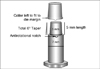
A metallic die (Fig. 1) was fabricated to simulate a prepared maxillary first premolar considering the average dimensions of the tooth according to Wheeler.48 The die had a flat end conical shape and 1 mm shoulder all around with rounded axiogingival line angle. Taper of the preparation was 6° according to the requirements of ideal crown preparation49 and as recommended by the manufacturers. The shape of die helped in standardizing the coping thickness and also easy standardization of veneering porcelain layer thickness. An anti-rotational notch was prepared on the margin to reproduce seating of the copings in same position at each stage of crown fabrication.
Fifteen specimens were prepared for each group. Group A consisted of cores prepared with Slip Cast technique of VITA In-Ceram sprint Alumina system (VITA Zahnfabrik H. Rauter GmbH & Co. Bad Säckingen. Germany) with aluminous veneering porcelain VITA VM7 (VITA Zahnfabrik, Bad Säckingen, Germany). Group B consisted of the cores fabricated with Plastic Foil Matrix technique of Turkom-Cera Fused Alumina Core System (Turkom-Cera SDN. BHD. Malaysia) with same aluminous veneering porcelain as group A.
Slip cast techniques is well known and documented in various literatures.14-17,23,28,32,33,38 The plastic foil matrix technique involves a 0.1 mm plastic spacer foil to be adapted on the die. The spacer foil is supported by a 0.6 mm plastic foil and heated over the flame till both starts sagging together. Then the die is dipped into a jar of silicon putty through the softened foils. The putty adapts the foil onto the die due to its viscosity. The supporting foil is removed and the spacer foil is cut till 1 mm below the die margin. Adaptation of spacer foil is refined using the edges of the supporting foil at the axiogingival line angle or any other line and point angles on the preparation. The slip (alumina gel) is then applied onto the die. After the slip is dry, it is remover with the spacer foil and placed for sintering. During sintering the spacer foil burns out and a porous framework is obtained. The remaining procedures are similar in both the techniques. The frameworks are finished to desired thickness and contour. Then the frameworks are examined for structural integrity with a checking liquid to rule out cracks developed during finishing. The frameworks with cracks are discarded and the intact frameworks are subjected to glass infiltration procedure. After glass infiltration no adjustments are possible in the copings except removal of excess glass. To simulate the fabrication procedure of a crown, veneering porcelain was built up over each core in three layers which are base dentine, dentine and enamel.
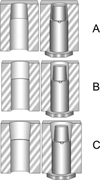
Measurement of marginal gap of all the samples were recorded at four stages e.g. coping (stage I), after base dentine layer firing (stage II), after dentine layer firing (stage III) and after enamel layer firing (stage IV). Copings were prepared as per respective manufacturers' instructions. The copings were approximately 0.5 mm in thickness and at the margin 0.3 to 0.5 mm thick collar was left to conform to the 1 mm shoulder of the die. Porcelain layers were standardized with three counter dies (Fig. 2) that helped building each layer to predetermined dimensions. No porcelain was added on the collar of shoulder margin left in the copings. All the laboratory procedures were done by a single person to avoid interpersonal variations.
Felton et al. discussed different terminologies used to define "The Fit" of a restoration.4 In this study the linear distance between the lowest outer margin of the coping and the cavosurface line angle of die margin along the long axis of the die was defined as the absolute marginal gap.50 As the die margin was perpendicular to its long axis, the marginal gap was measured perpendicular to the die margin.
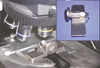
An optical microscope (Olympus BX 51) with image analyzing software (Image-Pro Express version 6.0.0.318, Media Cybernetics Inc.) was used for measurement on the digital photographs captured at 100 × magnification. An external light source directed light obliquely onto the marginal area of samples to illuminate only the outer surfaces of both copings and the die. The die was oriented transversely on the platform under the microscope keeping the die surface perpendicular to the direction of view. A custom made magnetic die orientation device (Fig. 3) was prepared to standardize orientation of the die under the microscope.
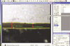
In every stage, six average values were recorded for each specimen at six fixed zones. The markings near the die margin helped reorientation of specific zones of the copings under the microscope. Thus, same areas of a coping were measured at all four stages. The copings with overextended margins at any of the focusing zones were not included in the study. Photographs of the marginal areas were captured at each zone at standardized orientation and placement of the samples. In all photographs margin was traced with the help of image analyzing software (Fig. 4). The coping margin which is mostly irregular was traced either manually or automatically by the software depending on the clarity and contrast of the coping margin on the photograph. Keeping the die margin at the horizontal line the average vertical distance between the trace line at die margin and the irregular trace line of coping margin was calculated by the software. Each focusing zone had a width of approximately 645 µm (= 702 pixels) at 300 dpi resolution and 100 × magnification. Therefore in one focusing zone, computed average marginal gap measurements can be explained as the average of 702 point measurements at each pixel level. Thus average of total 4212 (702 × 6) point measurements spread over 3.87 mm of margin (645 µm × 6) distributed at 6 zones represented overall marginal gap of each sample at each stage. Thus 30 samples at 4 stages generated total 720 average values from an equivalent of total 505440 point measurements.
Rotation of the samples while viewing under the microscope on the horizontal plane was corrected by rotating the captured photograph using the image analyzing software (Fig. 5). The software also allows superimposition of two photographs taken at two different levels of focus. Therefore, even if the margin of the coping and the cavosurface line angle of the die are at varying depth, two different photographs in the same spatial position of the specimen under the microscope were captured at different focusing level. Then superimposing the photographs both the die margin and crown margin were traced accurately (Fig. 6) and vertical distance between them was measured.
To determine the significance of difference between two groups, two-tailed unpaired 't' test was performed at each stage of crown fabrication. The magnitude of marginal distortion within the groups on porcelain firing was done with one way ANOVA test to know whether there was any significant change in marginal gap on porcelain firing. If significant results were obtained, the Tukey's post hoc analysis was planned for multiple comparisons to pin point the stage of crown fabrication where significant changes in marginal gap had occurred.
RESULTS
Two-tailed unpaired 't' test in Table 1 shows significant difference in mean marginal gap between groups at coping stage (P<.05) where Turkom-Cera plastic foil matrix technique showed lower values of marginal gap than slip cast technique. The difference in mean values was maintained even after three layers of porcelain firing, but it was not statistically significant.
The results of ANOVA test in Table 2 shows insignificant difference within the group on firing 3 layers of veneering porcelain. As the changes within group were found to be statistically insignificant, post hoc multiple comparison test was not carried out.
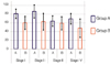
At coping stage mean marginal gap values (SD) were 81 (21) µm in group A and 60 (30) µm in Group B (Fig. 7). The observations in group A ranged between 0 to 186 µm and in group B it was between 0 to 216 µm at coping stage. Such great variation within samples and groups was maintained in all four stages and had significant influence on the statistical analysis. The standard deviations in both groups were large proving the fact that there were both well fitting and poorly fitting zones within the groups and also within the same sample.
In both groups, mean marginal gap is increased on first layer firing. Finally at stage IV in both groups, marginal gap was reduced and was lesser than the initial values at coping stage. Even though there were obvious changes occurring in mean marginal gap values with porcelain firing, the changes were statistically insignificant due to large values of standard deviation. The differences of mean marginal gap between stage I and stage IV were 11.75 µm for group A and 11.94 µm for group B.
DISCUSSION
In this study, cementation of the coping during measurement was avoided to eliminate the variability in cementation procedure for each coping in terms of viscosity of mix and force applied. Further it would have severely complicated evaluation of marginal stability on three consecutive firing of veneering porcelain. Measuring marginal opening of sectioned specimens under a microscope can be misleading. It gives impression that the marginal openings are the same along the entire circumference of the crown as stated by Chan et al.31 Further it destroys the samples and cannot be used for investigation of marginal stability on porcelain veneering.
Measurement with an optical microscope has the disadvantage of limited depth of view field.28 Unless the two points to be measured are on the same plane, it is not possible to focus on both points at a time. In this study, this problem was solved with the Image analyzing software which allows superimposition of two photographs of the same zone captured at two different levels of focus (Fig. 6).
Groten et al.51 determined minimum number of marginal gap measurements required for in-vitro testing. According to his data, 50 measurements per crown are suggested, but at least 20 to 25 measurements per crown are required according to the aimed precision level. Measuring crown margins at 4 to 12 sites per crown might be misleading; particularly when the fit of different crown systems or manufacturing stages are compared. This potential lack of relevant and consistent information should be compensated by large number of samples per group. However, in many studies 5 - 10 specimens were examined in each group.14,15,17,28,29,33,35,37 In all these studies points measurements were recorded to evaluate marginal gap ranging from 4 to 100 sites. To make adequate number of measurements in this study average width of the marginal gap in the whole focusing zone of 645 µm was measured at 6 different sites of each coping rather than taking measurements at limited number of points. Total average gap at 3.87 mm of margin (645 µm × 6) consisting of an equivalent of 4212 point measurements distributed at 6 zones represented overall marginal gap of each sample. Moreover to fulfill the requirement of adequate data, 15 samples in each group were evaluated. Measurements recorded at the same zones at all four stages increased relevance of the comparisons.
Previous studies indicated large variations of marginal gap within single crown system. The marginal gap of 87 (21) µm for Vita In-Ceram sprint alumina copings is in accordance with the range of values observed in previous studies with conventional In-Ceram. However, Pera et al. (27.5 µm),14 Rinke et al. (34 µm),33 Shearer et al. (22 µm)38 and Balkaya et al. (57 µm)28 found lower values whereas Yeo et al. (112 µm)23 and Sulaiman et al. (161 µm)17 reported higher values of mean marginal gap for conventional In-Ceram core system. There are no previous studies available in the literature regarding marginal fit of copings fabricated by Turkom-Cera plastic foil matrix technique. The mean marginal gap of 60 (30) µm for Turkom-Cera falls within the range of reported marginal gap of various all ceramic systems already existing.
Because of high variation of the values within same crown system, the mean value of all measurement locations shows a large local variation and results in an increase in SD. The mean values of the present study were accompanied by large SDs in the range of 21 to 42 µm. There is a wide range of SD values reported in few previous researches done with conventional In-Ceram14-17,23,28,32,33,38 and it was as high as 55 µm in the study conducted by Yeo et al.23
Firing shrinkage of veneering porcelain may cause dimensional changes in the underlying coping and influence marginal stability.17,21,26 The present study shows statistically insignificant change in marginal gap on application of veneering porcelain which is in agreement with several previous studies conducted by several authors like, Pera et al.,14 Sulaiman et al.17 and Yeo et al.23 There is reduction of mean marginal gap which is in contrast with the studies by Balkaya et al.28 and Sulaiman et al.17 Balkaya et al.28 reported significant change in marginal fit in conventional In-Ceram crowns and also reported that there is a tendency of labiolingual diameter of the crown to decrease with concomitant increase in the mesiodistal diameter. Sulaiman et al.17 found significant increase in marginal gap at the lingual region of the anatomic test specimens. He also showed positive correlation between the magnitude of marginal distortion and bulk of porcelain over the coping. Similarly, Balkaya et al.28 attributed the difference in marginal distortion at various regions of a crown to variable application of porcelain mass. In this study, the geometric shape of the die allowed to standardize thickness of porcelain layers in all directions. Coping configuration also differs from the anatomical situation of a maxillary central incisor used as master dies in previous studies of Sulaiman et al.17 and Balkaya et al.28 The configuration of the copings and the pattern of porcelain application in this study can be closely compared to the mesial and distal area of the maxillary central incisor and thus can be co-related with the increase in the horizontal diameter of the copings reported by Balkaya et al.,28 causing better seating of the copings and improved average marginal fit.
The differences between the results of present study and the results of other studies are possibly due to various factors like, die configuration and material, method of measurement, location and number of measurements and measurement of cemented or noncemented crowns.
Dental literature reports that, although a marginal opening equal to that of 25 to 35 µm grain size (ADA specification No. 8) is acceptable, measurements in the clinical situation consistently exceed the defined value. Christensen19 reported that the range of clinically acceptable marginal gap was 34 - 119 µm for subgingival and 2 - 51 µm for supragingival margins, whereas McLean and von Fraunhofer30 concluded that 120 µm was the maximum acceptable marginal opening. Lofsrom and Barakat25 reported clinically acceptable marginal gap values of 7 - 65 µm. Considering all these studies, the mean marginal openings for both groups in this study were within the range of clinical acceptability with mean marginal gap of 70 (24) µm for Vita In-Ceram sprint system and 48 (42) µm for Turkom-Cera after porcelain application.
There are several limitations in this study. Studies may be conducted with anatomic dies, measurements of marginal gap recorded after cementation, fixed partial denture situation, artificial aging etc. which will increase the clinical relevance. Slip cast technique has been investigated by several researchers.14-17,23,28,32,33,38 Further investigations are necessary overcoming the limitations in this study to achieve more information about plastic foil matrix technique.
CONCLUSION
Within the limitations of this study, the following conclusions can be drawn:
Plastic foil matrix technique produced copings with better marginal fit (at coping stage) as compared to slip cast technique.
After firing three layers of veneering porcelain, copings of both group showed comparable marginal fit.
Both techniques produced crowns that showed marginal gap within the clinically acceptable limits reported by previous researchers.
There was no significant marginal distortion in both systems on firing veneering porcelain over the copings.


 XML Download