

 PDF
PDF ePub
ePub Citation
 Print
Print


INTRODUCTION
Osseointegrated implants have provided alternative treatments to conventional prostheses for patients who lost their teeth and achieved predictable long-term results.1,2 An accurate and passively fitting prosthesis as well as successful surgical operation is suggested as one of the critical requirements for long term implant success.3-8
Since the uneven distribution of occlusal loads and torquing stresses on the various elements due to problems related to poor fit of frameworks connected to implant may lead to marginal bone loss and failure of implants as well as in relation to mechanical problems as loosening of screws and fatigue fractures of implant components.4-10
It will probably not be possible to connect a multi-unit implant prostheses with a completely passive fit in clinical situation because there are many potential inaccuracies with current materials and techniques, which include dimensional changes in impression materials, expansion of gypsum die product, dimensional changes in wax and acrylic pattern, dimensional changes in investment materials and volumetric shrinkage of metal casting on solidification.11
Among these variables, the precise transfer of the spatial relationships of implants from the mouth to the master cast with an impression is the first and critical step to ensure passive fit of implant framework. Therefore, clinicians should strive for improving the transfer accuracy of the impression copings.12-14
Various techniques have been suggested to achieve an accurate master cast. Squared impression coping15-18 and custommade, open-top impression tray19-21 were recommended instead of tapered impression coping and stock impression tray.
In regard to splint the impression copings, there are many controversies exist since Brånemark et al. emphasized the importance of splinting impression copings together before registration of impression.22
Humphries et al.,12 Hsu et al.,23 Philips et al.,24 and Herbst et al.25 found no significant differences between the values obtained with acrylic-splinted versus unsplinted groups in impression techniques.
Spector et al.26 also investigated the accuracy of three varied impression procedures using the direct and indirect transfer copings. Though the study involved multiple variables of techniques and materials, the consistent findings was one of distortion resulting from the transfer manipulations. The common practice of joining the direct transfer copings with acrylic resin is an attempt to stabilize the copings against rotation during fixture or abutment analog fastening, control the relationship between implants in a rigid fashion. In their study, a definite advantage for this practice has not been shown. The same objective could be partially accomplished with a rigid impression material or an elastic material with a low flexibility, both of which do not introduce the polymerization shrinkage variables inherent in the use of acrylic resin. Interregui et al.27 and Burawi et al.28 showed better result with unsplinted group using polyether or additional silicone impression material alone and presumed the main reason of distortion with resin splinted group possibly occurred by the residual polymerization shrinkage.
However, Assif et al.29 and Naconecy et al.30 showed that splinting technique was significantly more accurate than unsplinted techniques. Vigolo et al.31 suggested that the impression technique involved square impression copings joined together with autopolymerizing acrylic resin or square impression copings, previously airborne particle-abraded and adhesivecoated could improve accuracy of the master cast than non-modified squared transfer coping without splinting. Cabral et al.32 compared 4 impression techniques and direct impression technique with square impression coping with acrylic resin splints sectioned 17 minutes after setting and welded with the same resin before impression making showed better results than other techniques studied. Also Rhyu et al.33 suggested vinyl polysiloxane (VPS) bite registration material as a splinting material and found impressions made with square impression coping splinted with VPS bite registration material were better than acrylic resin splinted group and unsplinted group.
The purpose of this in vitro study was to evaluate the effect of dimensional stability of splinting material on the accuracy of master casts.
MATERIALS AND METHODS
A stainless steel metal model (SS 316, Seoul, Korea) with six 3.75 × 10 mm ad modum Brånemark external hex implant (29108: Noble Biocare, Göteborg, Sweden) was fabricated.
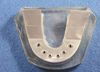
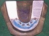
The fixtures were widely distributed throughout the stainless steel model to simulate fully edentulous condition. This metal model was embedded in epoxy resin to serve as (Fig. 1).
To make accurate impressions for fabrication of sample casts, custom impression tray incorporating 6 squared transfer copings was fabricated using light-polymerizing tray material according to manufacturer's instruction (Triad Tru-Tray; Dentsply International Inc, York, PA, USA)(Fig. 2). For uniform thickness of impression materials, the 6 squared transfer copings were attached to each implant fixtures and were covered by 2 layers of baseplate wax (Kims international, Seoul, Korea). The impression tray was designed to have superior openings for the access of guide pins.
Impression procedures
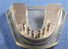
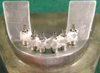
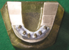
Six squared pick-up type transfer copings (29072; Nobel Biocare, Göteborg, Sweden) connected on each fixture with guide pins (Fig. 3). Impressions were made after 6 impression copings were splinted with each other using five different methods as follows. Group 1, squared transfer copings splinted with autopolymerizing acrylic resin (GC pattern resin; GC Corp, Tokyo, Japan) for 24hours and sectioned, reconnected just before impression procedure (Fig. 4).
Group 2, squared transfer copings splinted with autopolymerizing acrylic resin (GC pattern resin; GC Corp, Tokyo, Japan) 17 minutes before impression procedure (Fig. 5).
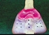
Group 3, primary impression was made around transfer copings with impression plaster (Snow-White plaster No.2; Kerr, Romulus, MI, USA) following manufacturer's instruction and then secondary impression was made with polyether impression material (Fig. 6).
Group 4, squared transfer copings splinted with impression plaster (Snow-White plaster No.2; Kerr, Romulus, MI, USA) over dental floss (Fig. 7).
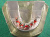
Group 5, squared transfer copings splinted with VPS bite registration material (Blu-Mousse; Parkell Bio-Materials, Farmingdale, NY, USA)(Fig. 8).
For every impression procedure, the impression material was machine-mixed (Pentamix;3M ESPE, Seefeld, Germany) and the mixed material was both syringed around impression coping and loaded in the impression tray. The impression tray was hand-pushed until its periphery meets the epoxy resin base and maintained in position with hand pressure.
Polyether impression materials (Impregum penta, 3M ESPE, Seefeld, Germany) were used for impression procedure except group 5 impressions (Fig. 9). They were made using additional type polyvinyl siloxane impression material (Dimension Penta H; 3M ESPE, Seefeld, Germany).
Laboratory procedures
After impressions were made, fixture analogs (29108; Nobel Biocare, Göteborg, Sweden) were screwed into squared transfer copings (29072; Nobel Biocare, Göteborg, Sweden) in the impressions. Each impression was poured with vacuum-mixed improved dental stone (ResinRock; Whip-Mix, Louisville, KY, USA). The casts were retrieved from the impressions after 24 hours.
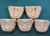
From master model, 5 impressions and experimental models were made for each of 5 splinting methods represented by group 1 to 5 (Fig. 10). Consequently, total 25 experimental models were obtained.
Measurements
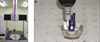
A computerized numerical control (CNC), coordinate measuring machine (CMM) (STRATO Bright 710; Mitutoyo Corporation, Tokyo, Japan) was used for all coordinate measurements (Fig. 11A). The accuracy of this CMM was less than 0.0001 mm for the x, y, and z axes. All measurements were performed by the same operator using probe head (PH10M; Mitutoyo Corporation, Tokyo, Japan) and signal probe (TP7M; Mitutoyo Corporation, Tokyo, Japan). Geopak-win software (Mitutoyo Corporation, Tokyo, Japan) was used for geometric transformation and data processing (Fig. 11B).
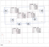
The coordinate system used throughout this study was defined as follows. The centroid of fixture or analog 1 which is on the right side of model was designated as the origin of coordinated system. The planar surface around it was regarded as XY plane. An imaginary line was laid on the ZX plane between centroid of cylinder 1 and the centroid of cylinder 6. Thus the centroid of fixture or analog 1 lay on the origin (0,0,0) and the centroid of fixture or analog 6 lay on the ZX plane (x,0,z) (Fig. 12). This coordinate system marks several dots on the elliptical plane created by platforms of fixtures or analogs and imaginary Z plane. The software convert ellipse to circle and determine centroids of each platform.
To evaluate the accuracy of each impression methods, coordinates of the centroids on the master model were located in three dimensions and compared with the coordinates of the centroids on the experimental casts obtained from 5 different impression methods.
Statistical analysis
Means and standard deviations were calculated for each item measured (i.e., each type of impression methods). A one-way analysis of variance (ANOVA) at a confidence level of 95% was used to evaluate the data and Tukey's studentized range test was used to determine significant differences between the groups.
RESULTS
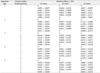
Table 1 shows means of actual distortion amount on each fixture analogs of 5 experimental models resulted from 5 different impression methods. The Δx, Δy, and Δz values are the amounts of displacement of each fixture analogs in the direction of axis from standard position (circle 1) and they were compared with x, y, z points of master model.
The difference of means for each of 3 distortion variables between master model and each splinting method are given as each entry in Table 2. The result of one sample T-test shows discrepancies in x, y and z axes between master model and each of 5 splinting method (P<.0001). Not any impression method perfectly duplicated the master model, but some extent of distortion values was clinically acceptable.
Table 3 shows comparison between the global means in each splinting methods. In x-axis, the mean distortion value of group 1 model was 14 ± 11.3 µm which was significantly less than other groups.
The mean distortion values of group 3: 19.6 ± 10.5 µm; group 4: 28.9 ± 20.5 µm; group 5: 31.2 ± 29.7 µm were found to have no significant difference. The maximum mean distortion value was measured in group 2: 32.1 ± 11.2 µm. In the same manner the mean distortion value of group 1 in y-axis was 7.4 ± 6.9 µm which was also significantly less than other groups. The mean distortion values of group 2: 18.4 ± 15 µm, group3: 19.5 ± 14.9 µm, group 4: 18.2 ± 18 µm were found to have no significant difference. The mean distortion value of group 5 in y-axis was 28.4 ± 23.6 µm and it was the largest among all groups.
Likewise, similar result was observed from z-axis as well, group 1 had the statistically smallest mean distortion value which was 8.6 ± 7.1 µm. The mean distortion values of group 3, group 4, group 5 model were 10.2 ± 7.6 µm, 25.7 ± 17 µm, 23.4 ± 17.9 µm, respectively and found to have statistically no significant difference between group 1, 3, 4, and 5. The mean distortion value of group 2 was 108 ± 57.7 µm that gave the worst results within all distortion data of experimental models (Table 3).
In summary, group 1 showed the smallest distortion and the mean distortion values of group 3 and 4 were shown to be the similar and next to group 1. On the other hand, group 2 showed relatively larger distortion than any other group.
DISCUSSION
Passive fit was described by Brånemark to be ideally in the 10 µm range.34 The definition has evolved to describe a clinically acceptable fit in which stress/strain conditions are within the physiologic range that enables the immature bone to mature or remodel in response to occlusal loads following prosthesis connection.
Inaccuracy can be related to horizontal and vertical errors. Horizontal fit discrepancy leads to binding of the screws and bending stresses in implant system and when vertical fit discrepancy is present, the preload is used to bring the mating surface closer together, which makes the screw vulnerable to fatigue fractures and loosening.35
Horizontal (x- and y-axes) displacement in relation to the master cast replicas contributes to a major part of the distortion of prostheses. However, the vertical dimension of distortion (z-axis) seems to increase more than the increase in the horizontal axis when tested in the mouth, which could be critical because this direction of distortion may be more related to introduce preload in the implant.36
It is known that there are some built in machining tolerances in each implant system but any discrepancy above the machining tolerance in the x, y or z axis may not allow a proper clamping effect of the components. Furthermore the amount of introduced stress may vary, depending on the stiffness of the framework for exactly the same degree of misfit. Thus, the biomechanical impact of fit between osseointegrated implants and superstructures seems to be complex, and there is at present time no answer to the question of what acceptable clinical fit should be.37
Also there are many variables with current materials and techniques that can influence clinical acceptable fit of implant framework but clinician must strive to overcome these variables.
The precise transfer of the spatial relationships of implants from the mouth to the master cast with an impression is the first and critical step to ensure passive fit of implant framework.
Various techniques had been introduced to get accurate impression and splinting of impression coping is one of those even if there are still controversies.
Some studies found no difference between splinted and nonsplinted technique.12,23-26 However, other studies showed that splinting may provide stabilization of transfer copings against torque from analog tightening and reduce rotational freedom within resilient impression material.29-33
And it is advocated splinting is the determining factor for the most accurate cast fabrication, regardless of impression material even though the polyether impression material is very rigid after setting.16,29
In the present study, authors compared autopolymerizing acrylic resin, impression plaster and VPS bite registration paste as splinting material to evaluate their effect of polymerization shrinkage of splinting material.
It has been reported that the total shrinkage of acrylic resin is between 6.5% and 7.9% in the first 24 hours, with 80% of shrinkage occurring in the first 17 minutes after mixing,38 whereas the setting expansion of impression plaster is between 0.01% and 0.12%.39
Perfect duplication of master model was impossible in all groups. Group 1, 3, and 4 showed clinically acceptable mean distortion value and the largest distortion were measured in group 2.27
Minimal distortion were found out in group 1 impression method using resin splinting for more than 24 hours, then sectioned and reconnected just before the impression procedure. Adequate polymerization time and the process of compensation seemed like the reason of best accuracy.
Thus, Dumbrigue et al.40 and Naconecy et al.30 presented simple and less time consuming procedure that can rigidly connect transfer coping and minimize the effect of resin polymerization shrinkage such as using prefabricating resin bar or carbon steel bar.
Assif et al.41 showed the efficacy of impression plaster as splinting material. They stated that impression plaster sets rapidly, is quite accurate and rigid, and does not bend or distort; it is also easy to manipulate, less time consuming and less expensive to use. The exothermic reaction is negligible.
Nissan et al. and Eid also described how to use impression plaster to make implant impression in their clinical studies and stated about the accuracy, easy of manipulation and decreased working time.42,43
On the other hand, the proper use of VPS bite registration material could be a doubt as a splinting material because of its short working time and low flowability although their dimensional stabilities are excellent. However, this study shows that the bite registration material was found out the similar accuracy compared to the impression plaster except the distortion values in y-axis.
CONCLUSION
Within the limitations of this in vitro study,
1. Splinting square impression coping with autopolymerizing resin, adequate polymerization time and compensation procedure before impression (Group 1 impression method) was found to be statistically the most accurate method of splinting (mean distortion values < 20 µm).
2. Clinically acceptable accuracy could be obtained from the splinting methods used with the impression plaster. Statistically significant difference was not found between the group 3 and 4 (Table 3).
3. The splinting method used with the VPS bite registration material showed statistically more distortion than impression plaster in y-axis. However, there was no statistically significant difference of accuracy in the x- and z-axes.
4. The impressions made with direct autopolymerizing resin splint method without compensation procedure (group 2) resulted in more distortion than other methods as a whole. Especially, there was a significant loss of accuracy in the z-axis with the high mean distortion value over 100 µm.


 XML Download