

 PDF
PDF ePub
ePub Citation
 Print
Print


Abstract
Introduction
Cone beam computed tomography (CBCT) has various advantages and is used favorably in many fields in dentistry. Especially, CBCT is being used as basic diagnostic tool for 3-dimensional analysis in orthognathic patient. Two-dimensional cephalograms can be synthesized from CBCT digital imaging and communications in medicine (DICOM) data. In this study, conventional cephalograms and CBCT were taken simultaneously, and representative landmarks were located and analyzed in its accuracy and reproducibility.
Materials and Methods
Ten patients who had orthognathic surgery in Wonkwang University Daejeon Dental Hospital participated in this study. For each patient, CBCT and conventional cephalogram was taken. By using Ondemand (Cybermad, Korea), 2-dimensional cephalograms was established on CBCT. In addition, 19 landmarks were designated and measured by 3 orthodontists twice a week. After these landmarks were transferred to a coordinate, distance of landmark and axis, standard error, distribution degree were measured, compared and analyzed.
Results
Comparing the CT ceph group and conventional cephalogram group, CT ceph group had shown shorter distance of landmark and axis in S, Hinge axis, Bpt, Ba, Or, Corpus left. Standard error of the mean shows that CT ceph group has better reproducibility in Or, Corpus left, Hinge axis at X axis and Na, U1R, U1T, Bpt, PNS, Ba Corpus left, Hinge axis at Y axis. In both groups, mean error was less than 1.00 mm, no significant difference were found between CT ceph group and conventional cephalogram group in all measurements. Furthermore, comparing two groups, each 17 landmarks out of 19 had its characteristic in distribution degree.
References
1. Broadbent BH. A new x-ray technique and its application to orthodontia. Angle orthod. 1931; 1:45–66.
2. Mah JK, Danforth RA, Bumann A, Hatcher D. Radiation absorbed in maxillofacial imaging with a new dental computed tomography device. Oral Surg Oral Med Oral Pathol Oral Radiol Endod. 2003; 96:508–13.

3. Tsiklakis K, Donta C, Gavala S, Karayianni K, Kamenopoulou V, Hourdakis CJ. Dose reduction in maxillofacial imaging using low dose Cone Beam CT. Eur J Radiol. 2005; 56:413–7.
4. Halazonetis DJ. From 2-dimensional cephalograms to 3-dimensional computed tomography scans. Am J Orthod Dentofacial Orthop. 2005; 127:627–37.
5. Huang J, Bumann A, Mah J. Three-dimensional radiographic analysis in orthodontics. J Clin Orthod. 2005; 39:421–8.
6. Kang JY, Lim SH, Kim KW. The reliability of the cephalogram generated from conebeam CT. Korea J Orthod. 2007; 37:391–9.
8. Kamiishi H, Miyasato Y, Kosaka M. Development of the 3D-cephalogram: a technical note. J Craniomaxillofac Surg. 2007; 35:258–60.
9. Mori Y, Miyajima T, Minami K, Sakuda M. An accurate three-dimensional cephalometric system: a solution for the correction of cephalic malpositioning. J Orthod. 2001; 28:143–9. application. Am J Orthod Dentofacial Orthop 1988;94: 327–37.
11. Baumrind S, Moffitt FH, Curry S. Three-dimensional x-ray stereometry from paired coplanar images: a progress report. Am J Orthod. 1983; 84:292–312.
12. Brown T, Abbott AH. Computer-assisted location of reference points in three dimensions for radiographic cephalometry. Am J Orthod Dentofacial Orthop. 1989; 95:490–8.
13. Trocme′MC. Sather AH, An KN. A biplanar cephalometric stereoradiography technique. Am J Orthod Dentofacial Orthop. 1990; 98:168–75.
14. Bae GS, Park SB, Son WS. The comparative study of three-dimensional cephalograms in linear and angular measurements. Korea J Orthod. 1997; 27:129–40.
16. McClure SR, Sadowsky PL, Ferreira A, Jacobson A. Reliability of digital versus conventional cephalometric radiology: a comparative evaluation of landmark identification error. Semin Orthod. 2005; 11:98–110.
17. Trpkova B, Major P, Prasad N, Nebbe B. Cephalometric landmarks identification and reproducibility: a meta analysis. Am J Orthod Dentofacial Orthop. 1997; 112:165–70.
18. Geelen W, Wenzel A, Gotfredsen E, Kruger M, Hansson LG. Reproducibility of cephalometric landmarks on conventional film, hardcopy, and monitor-displayed images obtained by the storage phosphor technique. Eur J Orthod. 1998; 20:331–40.
19. Farman AG, Scarfe WC. Development of imaging selection criteria and procedures should precede cephalometric assessment with conebeam computed tomography. Am J Orthod Dentofacial Orthop. 2006; 130:257–65.
20. Moshiri M, Scarfe WC, Hilgers ML, Scheetz JP, Silveira AM, Farman AG. Accuracy of linear measurements from imaging plate and lateral cephalometric images derived from conebeam computed tomography. Am J Orthod Dentofacial Orthop. 2007; 132:550–60.
21. Liu JK, Chen YT, Cheng KS. Accuracy of computerized automatic identification of cephalometric landmarks. Am J Orthod Dentofacial Orthop. 2000; 118:535–40.
10. Grayson B, Cutting C, Bookstein FL, Kim H, McCarthy JG. The three-dimensional cephalogram: theory, technique, and clinical.
7. Adams GL, Gansky SA, Miller AJ, Harrell WE Jr, Hatcher DC. Comparison between traditional 2-dimensional cephalometry and a 3-dimensional approach on human dry skulls. Am J Orthod Dentofacial Orthop. 2004; 126:397–409.
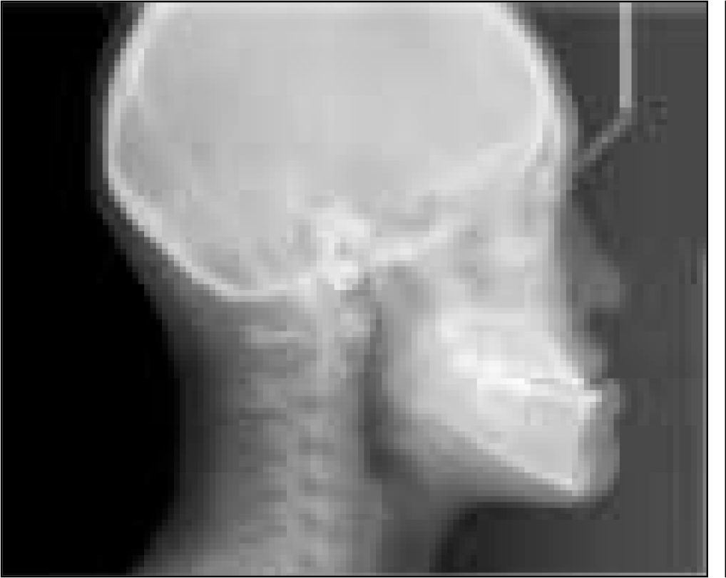
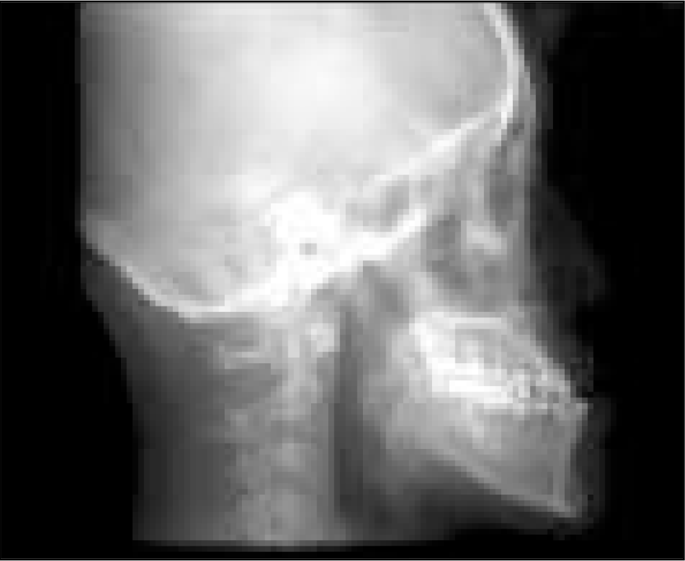
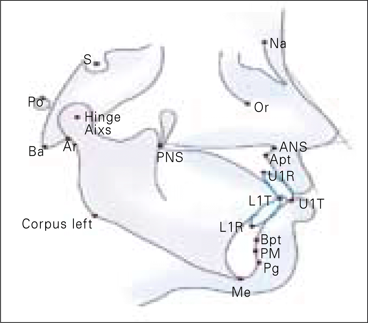
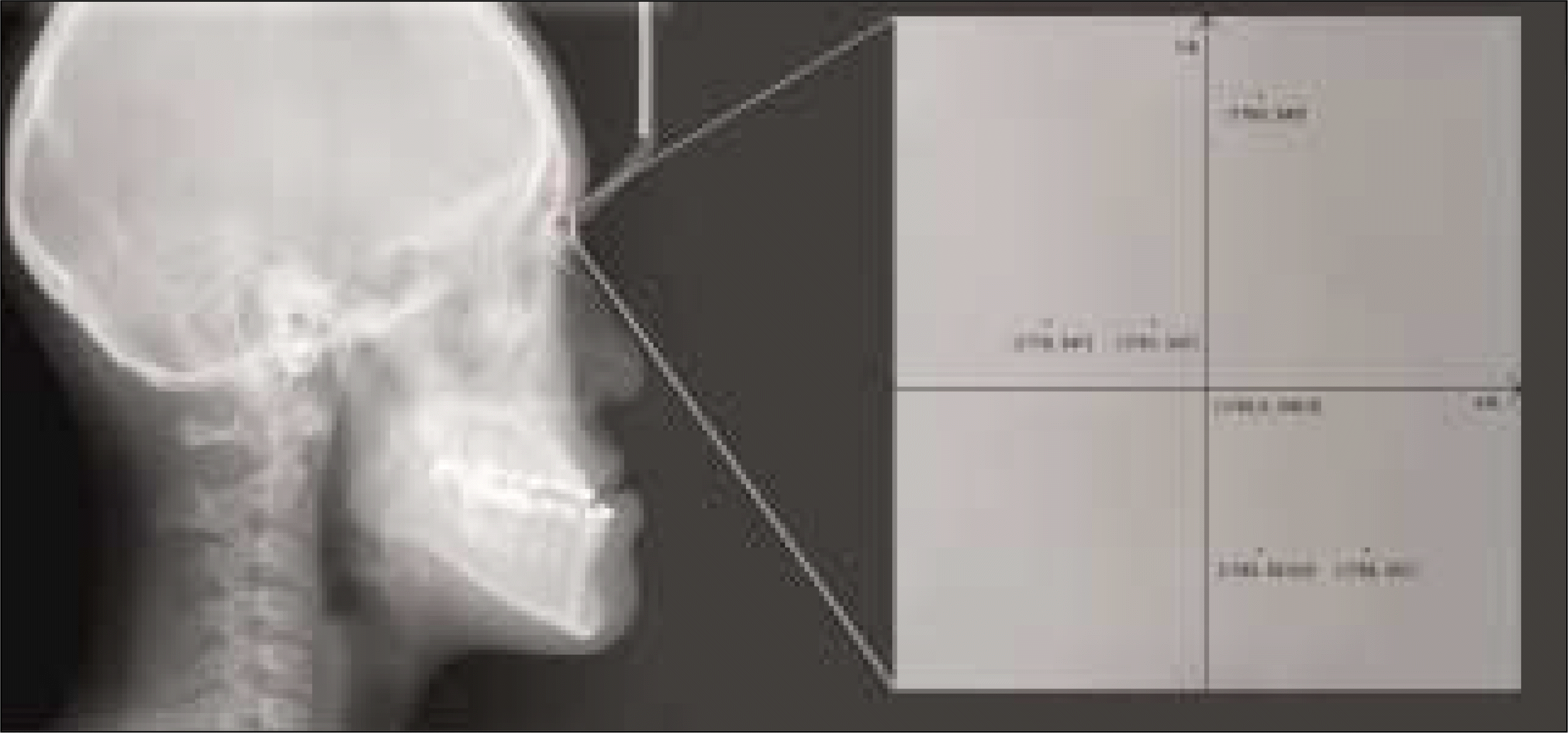
Table 1.
Distance from each coordinates to origin (mm) standard deviation (mm)/
Table 2.
Comparison of the mean errors for Digital ceph and CT ceph landmark identification along X and Y axes
 XML Download