This article has been
cited by other articles in ScienceCentral.
Abstract
Objective
This study aimed to investigate the effects of archwire form and power arm positions on maxillary incisors during lingual en masse retraction supported by miniscrew implants, using the finite element analysis method.
Methods
Sliding mechanics for lingual en masse retraction were simulated using the finite element method. Power arms were placed mesial and distal to the maxillary canine with straight and mushroom-shaped archwires. Miniscrews provided absolute anchorage for retraction force.
Results
When power arms were positioned mesial to the canine teeth, an increase in the intercanine distance was observed, while a decrease was noted when the power arms were distal to the canine tooth. Lateral incisors exhibited a greater torque loss, particularly when the power arm was mesial to the canine tooth. In the central incisors, the mushroom archwire resulted in intrusion, while the straight archwire showed an extrusion tendency. Movements in groups using the straight archwire were less controlled compared to those in groups using the mushroom archwire.
Conclusions
The archwire form and the position of the power arm affected the torque loss and vertical position of incisors during lingual en masse retraction supported by miniscrew implants. The most controlled movement was achieved with the combination of a power arm positioned distal to the canine tooth and a mushroom archform.
Go to :

Keywords: Finite element method, Orthodontic mini-implant, Lingual orthodontics, En-masse retraction
INTRODUCTION
The concept of lingual orthodontic treatment, as we know it today (i.e., multi-bracket system with mushroom form archwire), was first developed in the 1970s by Fujita in Japan.
1 Subsequently, with the aim of facilitating clinical practice, Scuzzo et al.
2 introduced the lingual straight wire (LSW) technique in 1995.
Lingual orthodontics differs from labial orthodontics in certain aspects, such as shorter interbracket distances leading to increased archwire rigidity,
3,4 variations in ligature type, force effects,
5 and the degree of freedom between brackets and archwires affecting friction.
6 Therefore, 0.018-inch (in) slot brackets are preferred for lingual orthodontic treatment, allowing for the use of less rigid archwires.
Different types of archwires used in lingual orthodontics have their unique advantages and disadvantages. Customized lingual archwires personalize the treatment entirely for the patient, but replacing the archwire when needed can be challenging. Straight form lingual archwires allow the application of sliding mechanics, prefabrication, and storability in the clinic which facilitates immediate wire replacement when necessary. Mushroom-shaped archwires, on the other hand, have better flexibility with wire length, while also offering the convenience of prefabrication and storability. Nevertheless, in mushroom-shaped archwires, complex bends are necessary which could influence treatment outcomes. However, it was noted that the LSW technique causes lingual brackets to be thicker, resulting in reduced interbracket space, gingival compression, and tongue irritation.
2
Space closure is often achieved using sliding mechanics in lingual orthodontics.
7 Recently, temporary anchorage devices have been employed to provide skeletal anchorage during anterior retraction. Mini-implants can be placed in the palatal region to provide absolute anchorage and prevent lingual tipping of the posterior teeth as part of the space closure process.
8 Power arms are positioned on the archwire as points of force application. By adjusting the length of the power arms and the position of the miniscrew, the desired movement path of retraction force is established according to the resistance center of the anterior segment.
7,9
In lingual orthodontic treatments, since they are often preferred by patients with esthetic expectations, the results should be esthetically satisfying. Particularly in premolar extraction treatments, there is a higher risk of torque loss in the incisors due to the lingual retraction force.
10,11 The various characteristics of retraction force have been investigated in previous studies; however, the features of archwires have not been extensively explored. Indeed, the forms of archwires used in lingual orthodontics directly impact all aspects of the appliance. Therefore, having a thorough understanding of the treatment outcomes of the employed lingual orthodontic system will significantly influence clinical preferences.
Finite element method (FEM) is a mathematical method that intricately and quantitatively examines the stress, strain, and displacement of structures with complex geometry. Therefore, this method enables a better understanding of the biomechanics involved in the retraction of anterior segments in lingual orthodontics. This study aimed to investigate the effects of archwire form and power arm positions on maxillary incisors during en masse retraction supported by miniscrew implants using the finite element analysis method.
Go to :

MATERIALS AND METHODS
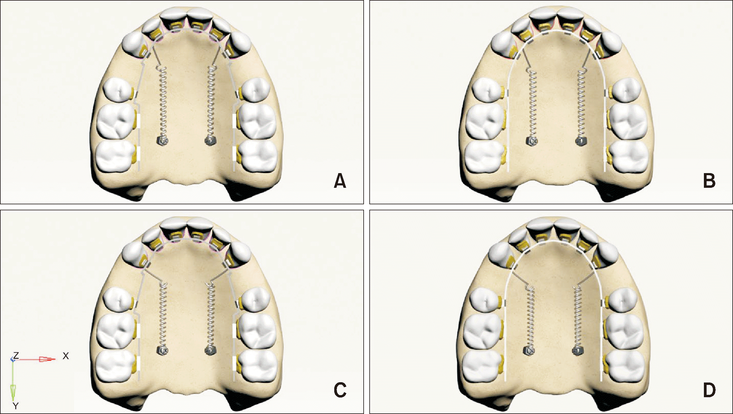
In the study, the effects of equal and uniform forces of 150 g applied sagittally and horizontally via nickel-titanium (NiTi) closed coil spring from power arms placed on the archwire to mini-implants were investigated on the sagittal, transversal, and vertical displacements of the maxillary incisors’ crown and apical regions. In
Figure 1, arrows indicating axes in the figures are located at the lower left corner, and the arrows denoted by “y” indicate the buccopalatal direction, those denoted by “x” represent the mesiodistal direction, and those denoted by “z” indicate the gingivocclusal direction. Displacement findings are expressed in millimeters (mm).
 | Figure 1In both straight and mushroom forms of 0.017 × 0.025-inch stainless steel lingual archwires, a 150-gram retraction force was applied parallel to the archwire to the miniscrews located between the first and second molars, originating from power arms placed mesial and distal to the canine tooth. A, Model 1 with a mushroom archwire and a power arm positioned mesial to the canine tooth. B, Model 2 with a straight archwire and a power arm positioned mesial to the canine tooth. C, Model 3 with a mushroom archwire and a power arm positioned distal to the canine tooth. D, Model 4 with a straight archwire and a power arm positioned distal to the canine tooth. 
|
Generation of the finite element model
The three-dimensional (3D) maxillary model, obtained using data from the Visible Human Project (The National Library of Medicine, FACT SHEETS Office of Communications and Public Liaison, National Library of Medicine, Bethesda, MD, USA), with extracted first premolars and aligned teeth was used. The model was segmented and transformed into a 3D model based on the appropriate Hounsfield values. Trabecular bone was derived from the 3D maxillary model using the offset method and was exported in stereolithography format. The 3D model was imported into ALTAIR Evolve software (Altair, Troy, MI, USA), where suitable maxillary cortical bone and tooth geometry were modeled. Periodontal ligaments of appropriate thickness (0.2 mm) were modeled based on the outer surface of the teeth.
All prepared models were correctly positioned in 3D space, and the modeling process was completed in ALTAIR Evolve software. The Spider Screw (Infinitas Mini-implant System, DB Orthodontics Ltd., Silsden, UK), 0.017 × 0.025-in stainless steel mushroom and straight form archwires, and brackets were modeled in ALTAIR Evolve software. The brackets were customized, featuring vertical and horizontal slots in the anterior and posterior teeth, respectively. Brackets designed for both archwire forms for the anterior teeth are presented in
Figure 2. Additionally, the vertical distance between the horizontal slots of these brackets and the incisal edges of the teeth has been measured and presented in
Table 1. Full compatibility of the bracket base and lingual tooth surface was ensured. Alignment between mesh structures was performed in ALTAIR Hypermesh software to enable force transmission between models.
 | Figure 2Brackets used for the anterior teeth: A, B, C brackets designed for a straight archwire, corresponding to central, lateral, and canine brackets, respectively; D, E, F brackets designed for a mushroom-shaped archwire, corresponding to central, lateral, and canine brackets, respectively. 
|
Table 1
The vertical distance between the horizontal slots of the brackets and the incisal edges of the teeth
|
Form of archwire |
Teeth |
Distance |
|
Straight form archwire (mm) |
Central incisor |
4,659 |
|
Lateral incisor |
4,589 |
|
Canine |
5,956 |
|
Mushroom form archwire (mm) |
Central incisor |
3,955 |
|
Lateral incisor |
3,830 |
|
Canine |
5,110 |

Mini-implants and power arms were positioned so that the force will correspond to the center of resistance (Cres) of the anterior six teeth. According to previous studies
12,13 aimed at determining the Cres of the anterior six teeth, the force vector was arranged to pass 14.5 mm apically and 9.5 mm distally from the incisal edge of the central incisor (
Figure 3).
 | Figure 3The relationship between the applied force vector and the center of resistance (Cres) in mushroom (right) and straight (left) archwire. 
|
Mathematical models were created by dividing geometric models into simple, small parts known as meshes. After the modeling process was completed in ALTAIR Evolve software, the models were mathematically created and prepared for analysis using ALTAIR Hypermesh software. For analysis purposes, the models prepared in ALTAIR Hypermesh software were transferred to the ALTAIR Optistruct analysis program in FEM format.
Material properties
Linear material properties, including elastic modulus and Poisson’s ratio, were used for the materials with specified values in the analyses. The material properties of the analyzed model were numerically defined as given in
Table 2.
7,14,15
Table 2
Material properties of the models
|
Material |
Young’s modulus
(MPa) |
Poisson’s
ratio |
|
Cortical bone |
13,700 |
0.30 |
|
Trabecular bone |
1,370 |
0.30 |
|
Tooth |
20,300 |
0.30 |
|
Miniscrew |
103,000 |
0.30 |
|
Bracket & wire |
205,900 |
0.30 |
|
Periodontal ligament |
50 |
0.49 |

Loading scenarios and boundary conditions
There is a uniform loading condition of 150 g for all models. In all four models, the force was applied from the power arm hook of the archwire to the mini-implant through a NiTi closed coil spring. Under these two loading conditions, a total of four analyses were performed for straight and mushroom archwire structures with different geometries (linear elastic, homogenous, and isotropic) (
Figure 1). Loading definitions were distributed to the node points in the application regions to prevent stress singularity in the relevant areas.
The models were constrained by limiting all degrees of freedom to restrict movements in all three axes at the node points located in the upper region of the cortical bone, ensuring immobilization of the models while allowing for the definition of boundary conditions.
Boundary conditions were defined at the terminations of the maxilla. In the models utilized in the study, zero degrees of freedom were assigned to the nodes located on the planes where the maxilla models’ cortical bone terminates, fixing the model at the end of the bone and eliminating the mobility of nodes in this region. No restrictions were placed on the movement of other node points throughout the model.
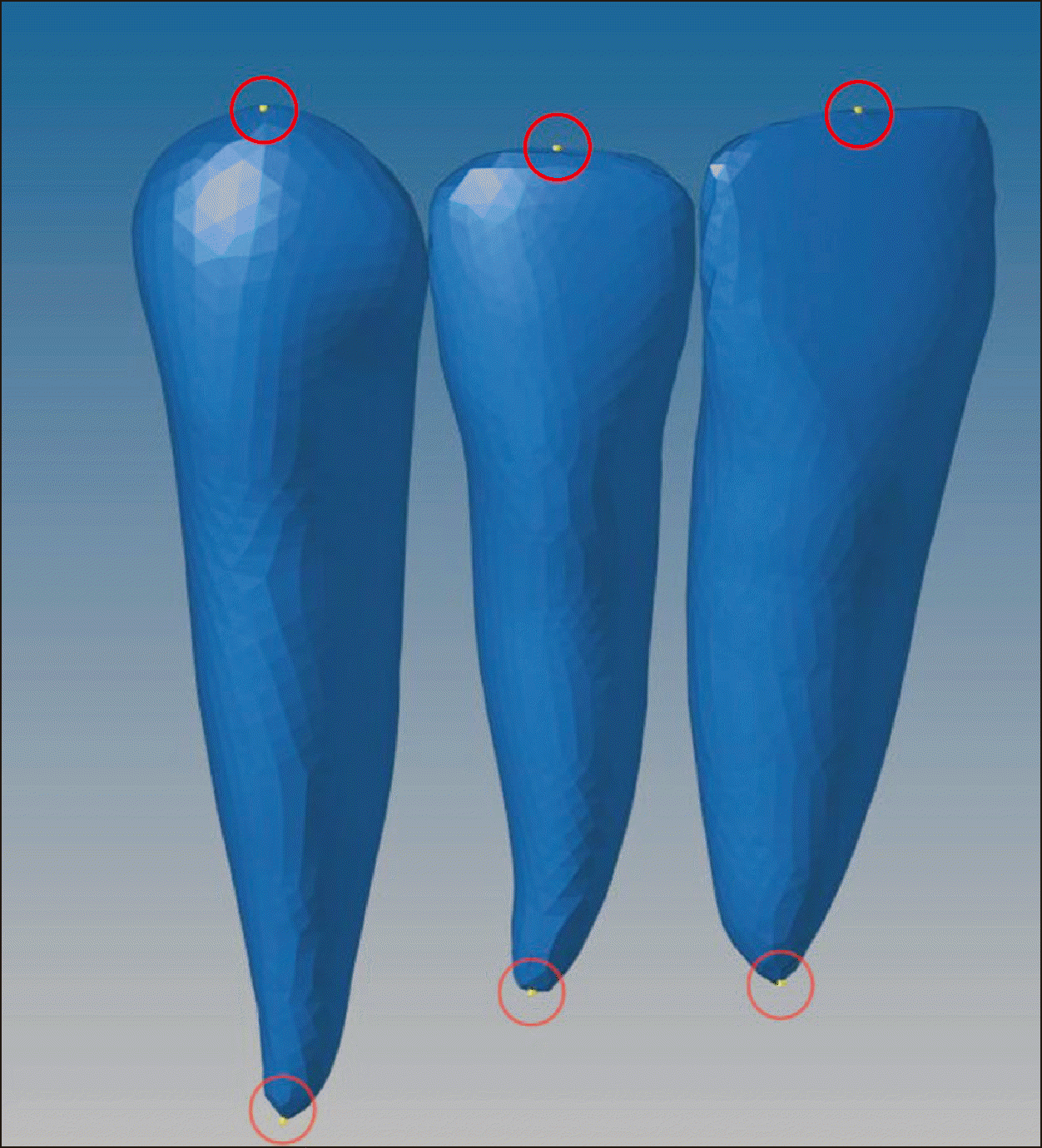
To simplify the expression of tooth displacements, reference nodes were placed on the crowns and roots. The amount of initial displacement of these landmark nodes on the X, Y, and Z axes after orthodontic force application was analyzed by FEM (
Figure 4).
 | Figure 4Location of selected nodes. The selected points were chosen based on their anatomical positions. For central and lateral incisors, these include the middle and most tip of the incisal edge, and the most tip of the apex. For canines, the most tip of the incisal edge and the apex were selected. 
|
Statistical analysis
In finite element studies, it is enough to validate the analysis results obtained by the software tools with finite element simulation instead of experimental readings. Thus, statistical analysis was not required.
Go to :

RESULTS
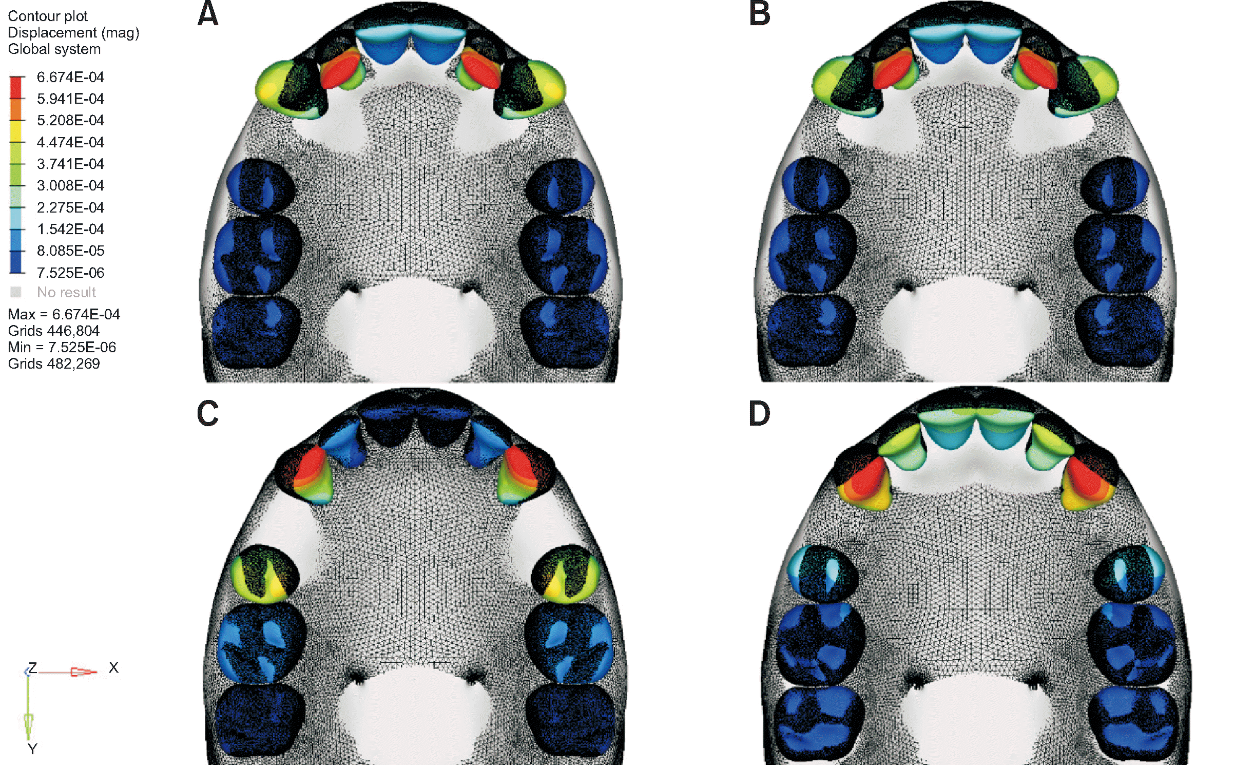
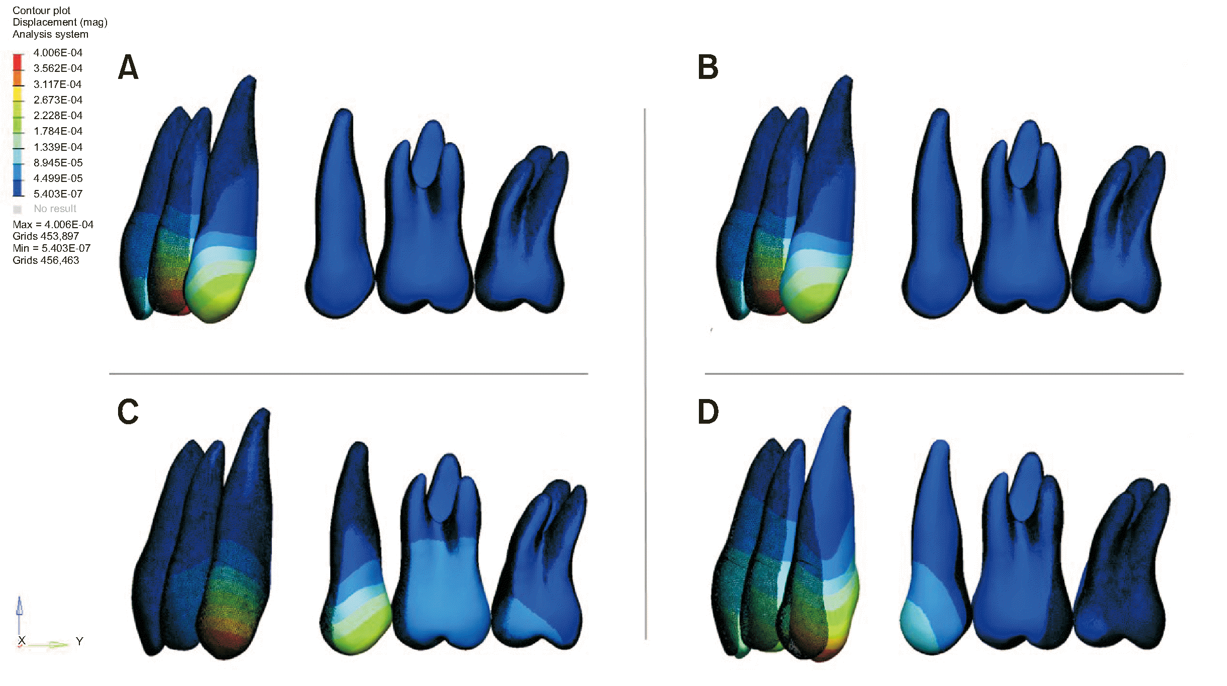
The movement patterns of incisors in the four models were repeated 1,000 times and presented in exaggerated visuals in
Figures 5 and
6. The letter “E” seen in
Figures 5 and
6 represents exponent or power and is used to express a number multiplied by the power of 10. Finite element stress analysis was performed on Hewlett-Packard (HP) workstations equipped with INTEL Xeon E-2286 (Intel, Santa Clara, CA, USA) processors operating at 2.40 GHz and 64 GB ECC memory. A minor degree of movement was observed in the posterior teeth due to the applied force, which were only visible in these exaggerated visuals.
 | Figure 5Movement patterns of incisors in the four models were repetitively simulated 1,000 times and presented in exaggerated visuals. A, Model 1 with a mushroom archwire and a power arm positioned mesial to the canine tooth. B, Model 2 with a straight archwire and a power arm positioned mesial to the canine tooth. C, Model 3 with a mushroom archwire and a power arm positioned distal to the canine tooth. D, Model 4 with a straight archwire and a power arm positioned distal to the canine tooth. 
|
 | Figure 6Sagittal plane views of exaggerated visuals. A, Model 1 with a mushroom archwire and a power arm positioned mesial to the canine tooth. B, Model 2 with a straight archwire and a power arm positioned mesial to the canine tooth. C, Model 3 with a mushroom archwire and a power arm positioned distal to the canine tooth. D, Model 4 with a straight archwire and a power arm positioned distal to the canine tooth. 
|
In all four models depicted in
Figures 5 and
6, parallel movement to the direction of force application was observed in the central incisors, albeit at different levels. Displacement data for central, lateral, and canine teeth in the models are presented in
Table 3. In the lateral incisors, greater torque loss and uncontrolled movement were observed in Models 1 and 2, compared to that in Models 3 and 4 along the Y axis.
Table 3
Numerical data from finite element stress analysis results
|
X axis*
|
|
Y axis†
|
|
Z axis‡
|
|
Incisal |
Apical |
Incisal |
Apical |
Incisal |
Apical |
|
Central incisor |
|
|
|
|
|
|
|
|
|
Model 1 |
–2.07E§-05 |
1.46E-06 |
|
1.03E-04 |
–2.91E-06 |
|
1.07E-04 |
3.43E-06 |
|
Model 2 |
–6.20E-06 |
8.30E-07 |
|
1.14E-04 |
–3.49E-06 |
|
–2.84E-05 |
–2.06E-06 |
|
Model 3 |
–7.60E-06 |
9.39E-07 |
|
1.79E-05 |
1.14E-06 |
|
3.00E-07 |
3.05E-06 |
|
Model 4 |
1.17E-05 |
9.44E-07 |
|
2.81E-04 |
6.42E-06 |
|
–9.81E-05 |
–2.56E-05 |
|
Lateral incisor |
|
|
|
|
|
|
|
|
|
Model 1 |
–8.98E-05 |
4.15E-07 |
|
3.79E-04 |
5.69E-07 |
|
–7.04E-05 |
1.29E-07 |
|
Model 2 |
–4.86E-05 |
–2.85E-07 |
|
4.02E-04 |
8.11E-07 |
|
–6.60E-05 |
1.20E-06 |
|
Model 3 |
–1.24E-05 |
2.97E-06 |
|
3.80E-05 |
2.82E-06 |
|
–1.04E-06 |
2.86E-06 |
|
Model 4 |
–5.19E-06 |
8.07E-06 |
|
3.73E-04 |
–2.49E-06 |
|
–8.77E-05 |
–8.25E-05 |
|
Canine |
|
|
|
|
|
|
|
|
|
Model 1 |
2.70E-04 |
–1.22E-06 |
|
1.56E-05 |
1.60E-06 |
|
1.93E-05 |
–1.62E-06 |
|
Model 2 |
2.36E-04 |
–1.45E-06 |
|
–4.28E-05 |
2.27E-06 |
|
2.14E-05 |
–9.62E-07 |
|
Model 3 |
–1.84E-04 |
3.11E-06 |
|
–1.50E-05 |
5.67E-06 |
|
–1.50E-05 |
5.67E-06 |
|
Model 4 |
–1.82E-04 |
1.02E-05 |
|
6.04E-04 |
–9.62E-06 |
|
–4.21E-05 |
9.45E-06 |

Similarly, displacement occurred in the canine teeth based on the position of the power arm, resembling the lateral incisor movement pattern. When the power arm was mesial to the canine tooth, the intercanine distance increased due to buccal tipping of the canine teeth. Conversely, when the power arm was distal to the canine tooth, a similar palatal tipping was observed in all incisors, leading to a decrease in the intercanine distance.
Among the incisors, the “Y” direction movements, which provided the most insight into torque loss according to the data in the tables, were more pronounced in Model 4 for the central, lateral, and canine teeth compared to those in the other models. Model 3 exhibited the lowest level of movement compared to the other models. Movements in the “Z” direction, representing occlusal direction, showed tendencies parallel to the tooth movements with arch forms in the central incisors. Extrusion was observed in the straight archwire, while intrusion occurred in the mushroom archwire. In the lateral incisors, extrusion was observed in all models. In the canine teeth, a parallel movement tendency was shown based on the position of the power arm, with intrusion when the power arm was mesial to the canine tooth and extrusion when it was distal.
Go to :

DISCUSSION
Changes in archwire forms in lingual orthodontics result in varying vertical heights of bracket placement in the occlusogingival direction. When using straight archwires, brackets are positioned more gingivally than when using the mushroom archwire. This allows the teeth to be placed closer to the resistance center within the bone, implying more controlled movement. However, this positioning causes the brackets to move away from the long axis of the incisors. The opposite scenario occurs when a mushroom archwire is used.
The tooth movement occurring in incisors due to applied retraction force can be influenced by factors such as periodontal condition and morphological features of the teeth.
16 Therefore, investigating the effects of different appliances on the same patient through FEM allows obtaining precise and objective results.
In treatments involving premolar extractions, torque loss during
en masse retraction is crucial for treatment outcomes. Chung et al.
17,18 introduced biocreative therapy in labial orthodontics, enabling anterior retraction without posterior appliances. Several studies have evaluated the effectiveness of this method in lingual orthodontics and have concluded it is effective for both incisor retraction and torque control.
19-21 However, in this method, certain malpositions in the anterior teeth limit the indications and requires fabrication of a cast splint. The ability of sliding mechanics to enable leveling and retraction with a single appliance provides greater practicality from a clinical perspective. The findings of this study also provide information about torque control with sliding mechanics. Optimal torque control is achieved through the combination of the power arm positioned distal to the canine tooth in the mushroom-shaped archwire.
In the literature, there are studies on different power arm lengths and positions, use of varying numbers and locations of miniscrews, segmental or continuous archwire use, and single or double archwire use.
7,22-26 The emphasized point in these studies is ensuring the correct force vector to achieve the intrusion and retraction of anterior teeth through the combination of these variables. Our study investigated the effects of changes in the positions and characteristics of brackets due to different archwire forms on the treatment. Therefore, the power arms were adjusted in a standard manner to intersect the force vector through the resistance center of the teeth.
The introduction of temporary anchorage devices in anterior retraction has enabled
en masse retraction with absolute anchorage in extraction cases. In sliding mechanics, adjusting the length of the power arm or the position of the miniscrew allows retraction forces to be applied in the desired direction according to the resistance center of the anterior segment.
9,27,28 In our study, the resistance center of the anterior teeth was assumed as indicated by Choy et al.
13
When the data along the X axis was examined in terms of displacement depending on the position of the power arm in all four models, it was observed that instantaneous displacements due to the force applied to the adjacent teeth of the power arm were more uncontrolled. This condition is illustrated as a distortion of the arch form in the exaggerated images of Models 1 and 2. However, the placement of retraction force more anteriorly due to this displacement, results in a difference in the X axis data, showing an increase in intercanine distance when the power arm is mesial to the canine and a decrease when it is distal, as demonstrated by Feng et al.
15 When examining other teeth, mesial tipping is observed in the central incisors for all groups except Model 4, and in the lateral incisors for all groups. In Model 4, central incisors exhibit a tendency for distal tipping. This may be attributed to the more uncontrolled movement in the other directions in Model 4 compared to that in the other groups.
According to the data from the Y axis, representing torque loss for central and lateral incisors in our study, it can be observed that Models 1 and 3, utilizing the mushroom archwire, show less tipping for the central incisors compared to Models 2 and 4, utilizing the straight archwire. When evaluated according to the power arm, more movement is observed in the central incisors when the power arm is distal to the canine. In the lateral incisors, models where the power arm is mesial to the canine have lost more torque than models where it is distal; but considering the arch form, less torque loss is observed in models with a mushroom archwire compared to those with the straight archwire. The movement of the canine incisor in the Y axis provides information both labiolingually and mesiodistally due to the position of the tooth. Therefore, the 3D displacements of the reference points need to be examined and interpreted together with the posterior movement of the tooth. Model 4 exhibited the highest displacement, featuring lingual tipping. In the exaggerated images, when the power arm is mesial to the canine, both rotation and buccal tipping were prominent in the teeth. Further, when the power arm is distal to the canine, palatal tipping was observed in the anterior teeth along with a more uniform movement pattern in the canines.
When the instantaneous displacements along the Z axis are examined, the occlusogingival displacements of the teeth can be interpreted with torque changes. Since the lateral incisors experience the most torque loss, extrusion occurs in all of them. However, for the central incisors, intrusion is observed with the mushroom archwire aligned parallel to the arch form, while extrusion is observed with the straight archwire. The canines exhibit an intrusive tendency when the power arm is mesial to the canine and an extrusive tendency when it is distal, in parallel with the position of the power arm.
The fact that FEM is a simulation constitutes a significant limitation of this study. Additionally, various details related to the bracket and lever arm were not considered, potentially influencing clinical outcomes. Moreover, our investigation focused solely on initial displacements rather than the continuous teeth movement. The findings of our study are essentially theoretical but provide valuable information for clinical references and expand the understanding the impact of archwire forms on treatments with lingual orthodontic appliances. Future FEM studies on continuous displacement and in vivo studies are recommended to verify the results of this study.
Go to :

CONCLUSIONS
In our study, we examined the effects of en masse retraction on incisor teeth using a 3D finite element analysis. We utilized lingual archwires with both mushroom and straight arch forms, placing power arms in two different positions–mesial and distal to the canine–while obtaining anchorage from miniscrews. The following conclusions were drawn:
Similar movement patterns were observed in the anterior teeth during retraction with power arms placed distal to the canine. En masse retraction performed with power arms placed mesial to the canine had a more pronounced effect, particularly on adjacent teeth to the power arm.
Applied retraction forces resulted in less torque loss and different power arm positions in models with mushroom archwires than in models with straight archwires.
The most controlled movements following retraction force were observed with the combination of a power arm placed distal to the canine and mushroom archwire.
Go to :


 PDF
PDF Citation
 Print
Print


 XML Download