This article has been
cited by other articles in ScienceCentral.
Abstract
Purpose
FLASH radiotherapy (RT) using ultra-high dose rate (>40 Gy/s) radiation is being studied worldwide. However, experimental studies such as preclinical studies using small animals are difficult to perform due to the limited availability of irradiation devices and methods for generating a FLASH beam. In this paper, we report the initial dosimetry results of a prototype electron linear accelerator (LINAC)-based irradiation system to perform ultra-high dose rate (UHDR) preclinical experiments.
Methods
The present study used the prototype electron LINAC developed by the Research Center of Dongnam Institute of Radiological and Medical Sciences (DIRAMS) in Korea. We investigated the beam current dependence of the depth dose to determine the optimal beam current for preclinical experiments. The dose rate in the UHDR region was measured by film dosimetry.
Results
Depth dose measurements showed that the optimal beam current for preclinical experiments was approximately 33 mA, corresponding to a mean energy of 4.4 MeV. Additionally, the average dose rates of 80.4 Gy/s and 162.0 Gy/s at a source-to-phantom surface distance of 30 cm were obtained at pulse repetition frequencies of 100 Hz and 200 Hz, respectively. The dose per pulse and instantaneous dose rate were estimated to be approximately 0.80 Gy and 3.8×10⁵ Gy/s, respectively.
Conclusion
Film dosimetry verified the appropriate dose rates to perform FLASH RT preclinical studies using the developed electron-beam irradiator. However, further research on the development of innovative beam monitoring systems and stabilization of the accelerator beam is required.
Keywords: Preclinical study, Electron linear accelerators, Ultra-high dose rate, FLASH radiotherapy, Film dosimetry
Introduction
FLASH radiotherapy (RT) using ultra-high dose rate (UHDR; >40 Gy/s) radiation is being studied worldwide [
1,
2]. However, experimental studies, such as preclinical studies using small animals, are difficult to perform due to the limited availability of irradiation devices and methods for generating a FLASH beam. Currently, prototype electron linear accelerators (LINACs) or modified medical LINACs are used for FLASH beam generation and preclinical experiments, with the exception of proton and particle therapy accelerators [
3,
4].
The generation of an appropriate FLASH beam for preclinical research purposes depends on the electron LINAC, an appropriate electron-beam energy, an electron-beam current, and a function to irradiate the beam for a significantly short time (~ms). In addition, scattering foils and collimators are required to generate the irradiation field, and the LINAC system needs to support a high repetition rate to achieve the required dose rate (>40 Gy/s). Recent studies on UHDRs using electron beams have used an electron-beam energy of approximately ≥4.5 MeV [
1-
3]. However, the energy required for preclinical research directly depends on the sample thickness.
In general, a film dosimetry system is preferred over clinical ionization chambers for dosimetric investigations of FLASH beams. This is because correction methods for high ion recombination effects or the significantly low ion collection efficiency in the air cavity of the ionization chambers under UHDR radiation are currently lacking [
3,
5,
6]. Consequently, this is widely acknowledged as an important challenge that needs to be solved in the field of physics with respect to the clinical application of FLASH RT [
3].
In this study, initial measurements of dosimetric parameters such as percentage depth dose (PDD), dose per pulse (DPP), and average dose rate (ADR) for a prototype electron LINAC-based irradiation system developed by the Dongnam Institute of Radiological and Medical Sciences (DIRAMS) Research Center in Korea were performed to demonstrate the feasibility of performing UHDR preclinical experiments. It should be mentioned that the detailed specifications of the complete prototype LINAC system have not been published yet, but they are briefly introduced in the Materials and Methods section.
Materials and Methods
1. Prototype LINAC and irradiation devices
A prototype LINAC was constructed for research on radiation therapy equipment at the DIRAMS Research Center, Korea. The LINAC uses a C-band accelerating column designed with a maximum energy of 9 MeV. The C-band accelerating column with energies of 4 MeV and 6 MeV was originally designed at the Pohang Accelerator Laboratory (PAL) and then redesigned at the DIRAMS Research Center with a maximum energy of 9 MeV [
7,
8]. The accelerating column has a total length of 64.4 cm and consists of a total of 24 cells fabricated by computer numerical control machines and brazed in a vacuum environment [
8,
9]. A radiofrequency (RF) of 2.5 MW generated by a C-band magnetron (CPI International Inc., Palo Alto, CA, USA) was applied to this prototype LINAC as a high power RF source. A power semiconductor switched-pulse modulator (Scandinova Systems AB, Uppsala, Sweden) was used to drive the magnetron, and an electron gun used as the electron-beam source was designed and fabricated in collaboration with PAL. Most of the subsystems of the LINAC, including the central control, interlock, and safety systems, were manufactured by the DIRAMS Research Center. An important function of this control system is to generate pulse-by-pulse beams for FLASH beam irradiation [
10]. This LINAC obtained a legal license from Korea Institute of Nuclear Safety (KINS) in 2022.
The irradiation device consists of an irradiation head and a small water phantom for preclinical experiments. Here, the irradiation head is composed of electron beam scattering foils and a collimator. Beam monitoring devices, such as monitor chambers and beam current transformers, can be included in the irradiation devices. The irradiation head used in the present study is equipped with a triple-scattering foil in a copper collimator. A more detailed description of the design and structure of this device can be found in Jeong et al. [
11]. The small water phantom can insert three cell tubes at a fixed depth of 1 cm for preclinical experiments. The phantom size is 10×10×12 cm
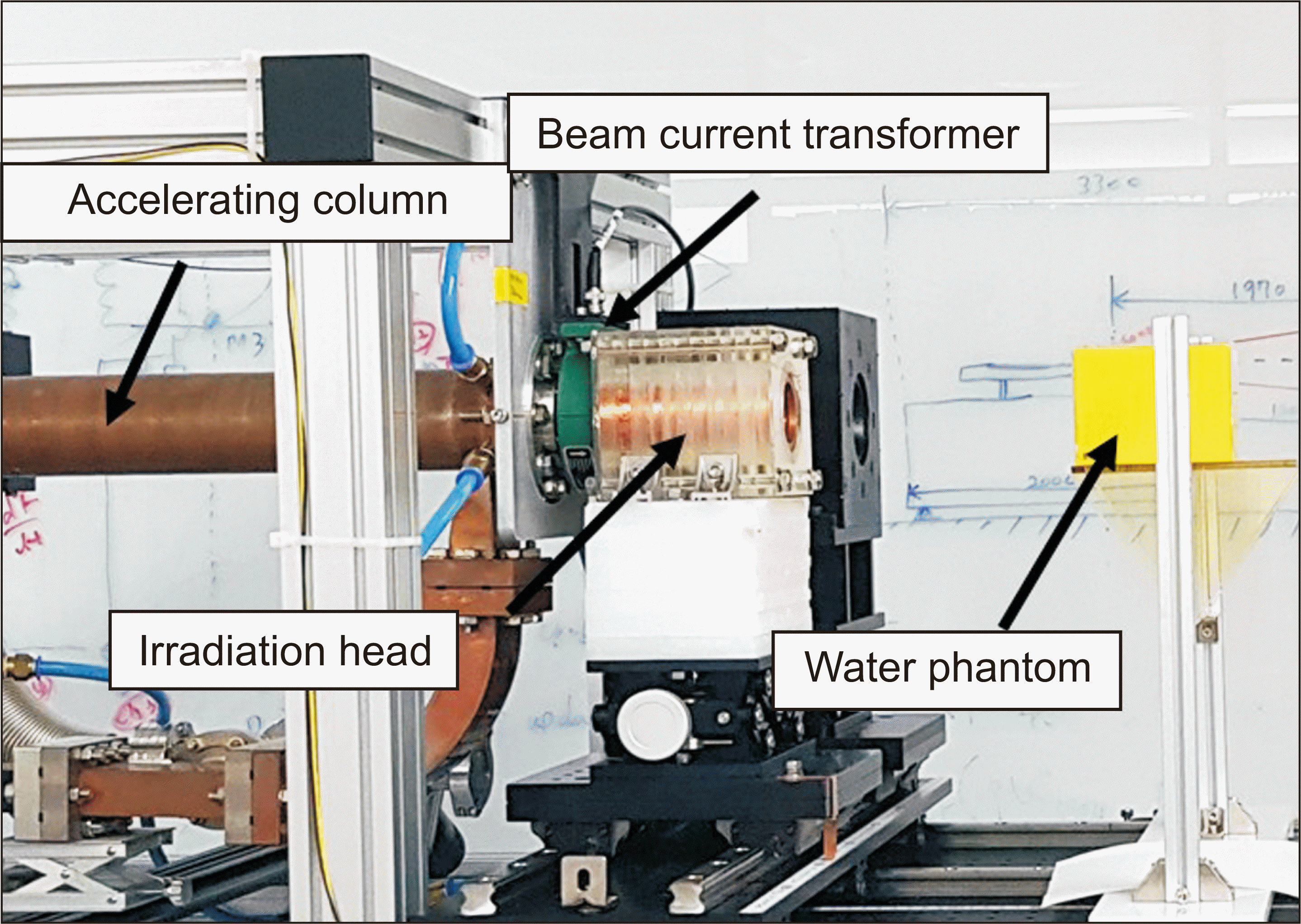
3. The front window and top plate of the phantom were made of a 0.2 cm thick acrylic plate. The remaining body of the device was manufactured using a three-dimensional printer. The top plate was designed in a way that to allow the insertion of cell tubes or dosimetric films to measure the PDD along the central axis and the dose at a depth of 1 cm. The experimental setup, including the accelerating column, is shown in
Fig. 1. The source to surface distance (SSD) was 30 cm. In this experiment, the source position was defined as the first position of the scattering foil on the irradiation head.
2. Experiments
To measure the electron-beam dose, the present study used film dosimetry and a radiochromic film (GAFchromic
TM EBT-XD; Ashland, Wilmington, DE, USA) with a dose range of up to 40 Gy. Radiochromic films are known to exhibit negligible dependence on the dose rate and the type of radiation [
3]; however, calibration and reading should be performed with caution because the overall uncertainty of film dosimetry is approximately 5% [
3].
Film irradiation for calibration purposes was performed using another electron LINAC at the DIRAMS Research Center. To reduce the uncertainty in each measurement, film irradiation and reference dose measurements were performed simultaneously by attaching a piece of film to the waterproof cap of an Advanced Markus
® chamber (PTW, Freiburg im Breisgau, Germany) in the water phantom. The reference dose was measured at a depth of 1 cm in the water phantom using the International Atomic Energy Agency (IAEA) TRS-398 protocol [
12]. Therefore, the depth difference between the chamber and the film position was approximately 0.1 cm. However, because these two depths were measured at the maximum dose depth, we assumed that the same dose was delivered to the chamber and film. When irradiating the calibration film using the electron LINAC, the phantom was located at a SSD of 80 cm, the dose rate measured by the Advanced Markus
® chamber was 10.8 Gy/min, and the ion recombination effect was estimated to be approximately 2%. The irradiated doses for film calibration were 0.542, 1.028, 3.272, 5.351, 6.387, 10.754, 15.661, 19.758, 28.695, and 38.077 Gy (total of 10 doses). FilmQA Pro
TM (Ashland) software was used to read the irradiated films and establish the film calibration curve.
The energy of the electron beam is inversely proportional to the electron-beam current, as opposed to the dose which is proportional [
13,
14]. Here, the beam current was measured using a beam current transformer (Model 2100; Pearson Electronics Inc., Palo Alto, CA, USA) installed between the accelerating column and the irradiation head, as shown in
Fig. 1.
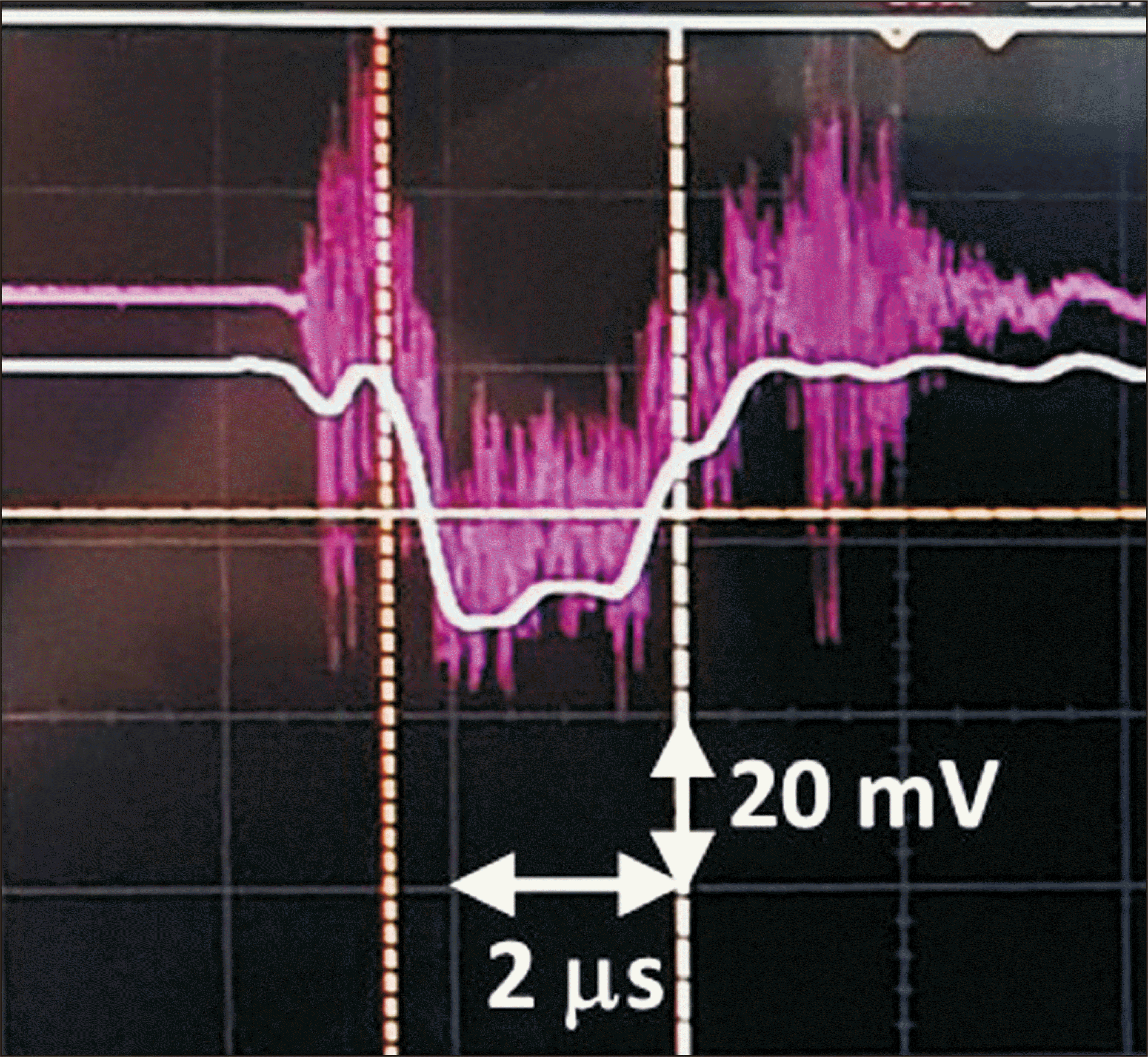
The shape of the beam current pulse measured with a 200 MHz oscilloscope (MSOX3024T; Keysight, Santa Rosa, CA, USA) is shown in
Fig. 2. In this figure, the pulse width is approximately 2.1 ms. A beam current transformer with a voltage-to-current ratio of 1:1 showed that the pulse beam current was 30 mA.
From a dosimetric perspective, the energy of the electron beam can be estimated from the PDD curve. According to an IAEA technical report (TRS-277), the most probable energy (
Ep) and mean energy (
E0) for an electron beam at the phantom surface can be estimated from the depths of
Rp and
R50 on the PDD curve as follows [
15]:
where Rp is the practical range of the electron beam and R50 is the depth at which 50% of the maximum dose on the central axis of the beam is attained. In this study, both depths were determined from the measured PDD data in water.
The experiment was conducted in two stages. First, the PDD curves according to the beam current were measured at a low pulse repetition frequency (PRF) of 10 Hz, whereas the e-gun heater current was varied gradually. Based on the PDD results obtained, we determined the most suitable beam current conditions for our preclinical experiments. Second, at the, PDD and dose measurements were performed under high PRFs of 100 Hz and 200 Hz using the determined beam current to verify the achievement of a UHDR.
A depth of 1 cm was considered appropriate as the reference dose depth for cell tube or mouse irradiation in the preclinical experiments. Pertaining to the dose measurement, all films were irradiated with 20 electron-beam pulses by inserting a piece of the film to a depth of 1 cm in a direction perpendicular to the beam in the phantom. In addition, the PDD curves were measured for the two PRFs to verify that PDD remained constant at high PRFs.
In the following section, the energy parameters analyzed using the measured PDD curves with respect to the beam currents are described. Furthermore, the DPP, instantaneous dose rate (IDR), and ADR measured with film dosimetry at 100 Hz and 200 Hz are presented.
Results
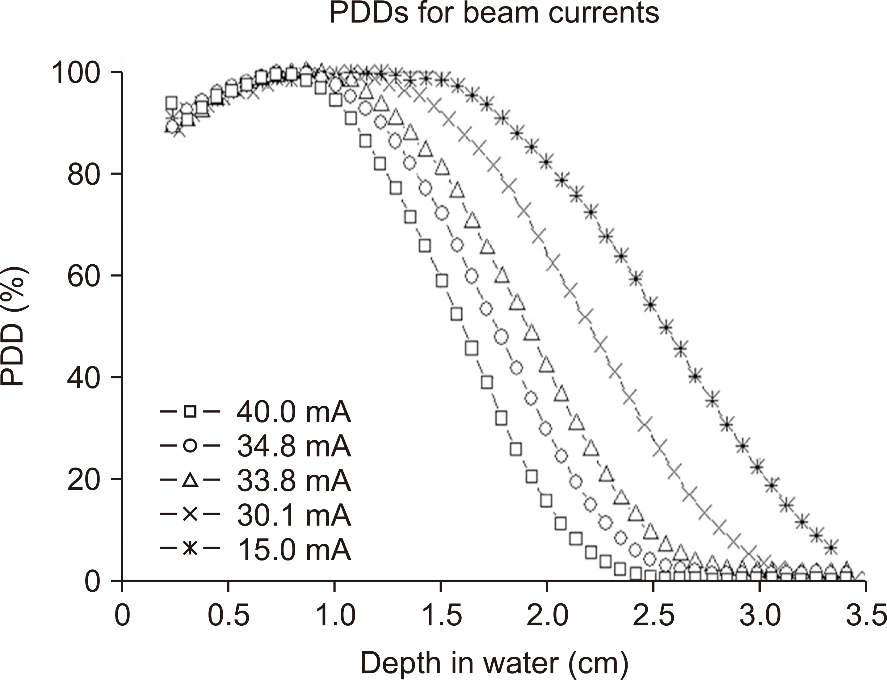
Fig. 3 demonstrates the PDD curves measured with film dosimetry according to the electron-beam current, and
Table 1 lists the calculated energy parameters for each PDD curve using Eq. (1) and (2). As shown in
Fig. 3, the PDD curves shifted to the left as the beam current increased. Consequently, as mentioned earlier, the energy of the electron beam also decreases with increasing beam current (
Table 1). The depth of the maximum dose (
R100) was approximately 1 cm except when the beam current was 40.0 mA.
At a beam current of maximum 34.8 mA, the PDD at a depth of 1 cm was >98%. When estimating DPP at a depth of 1 cm from the raw data of the depth dose measured film, our results showed that the DPP for the beam current was 1.2 Gy at 40 mA, 0.56–0.61 Gy at 30–35 mA, and 0.27 Gy at 15 mA. At a beam current of 40 mA, the dose was high, and the energy was low. However, at 15 mA, the energy was high, and the dose was low. Therefore, a beam current range of 30–35 mA was deemed appropriate for electron-beam irradiation. The following are the measurement results for. During irradiation with the UHDR beam generated by the high-PRF operation of the LINAC, the beam current was maintained at 30–33 mA by adjusting the power supply to the e-gun heater.
Fig. 4 shows the irradiated films at high PRFs of 100 Hz and 200 Hz, where one film on the left is for the depth dose and other three are irradiated films with an equal number of pulses at a depth of 1 cm in a direction perpendicular to the beam. Because all films, including the PDD film, were irradiated with an equal number of pulses, four dosimetry results were obtained at a depth of 1 cm.
Moreover,
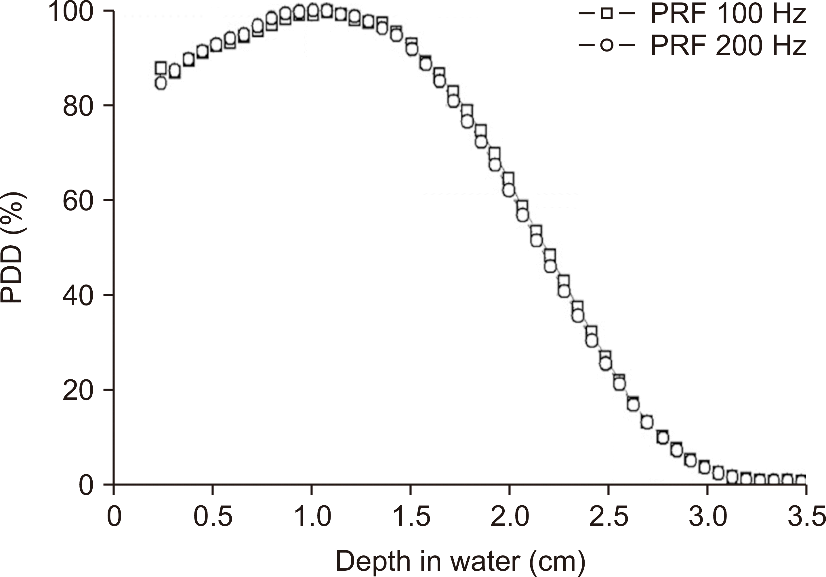
Fig. 5 exhibits the PDD curves measured at 100 Hz and 200 Hz, highlighting that there was no significant difference between the PDD curves. However, we noted a marginal increase in the energy level compared with the results shown in
Fig. 3, which were obtained by irradiation at 10 Hz at a similar beam current. The average and most probable energies determined from the PDD curves were 5.2 MeV and 5.8 MeV respectively, and the maximum dose depth was improved (
Fig. 5).
The film dosimetry results are listed in
Table 2. Here, IDR=DPP/t, ADR=DPP×PRF, and the pulse width, t was 2.1 ms [
3]. The average film dose for 20 pulses was approximately 16 Gy, and the standard deviation of the four film dosimetry results reached ±1.06 Gy (±6.5%) at 200 Hz, as shown in
Table 2. As a factor related to UHDR, DPP was approximately 0.8 Gy, and the ADRs for 100 Hz and 200 Hz were 80.4 Gy/s and 162.0 Gy/s, respectively.
Discussion
The present study initially evaluated the relationship between beam current and energy to determine the optimal preclinical experimental conditions. Our results showed that the most suitable beam current band for preclinical experiments was approximately 33 mA, corresponding to mean and most probable energies of 4.4 MeV and 5.4 MeV, respectively, at the phantom surface. In this study, energy was considered as a quantitative indicator of the energy-dependent PDD curve.
The dose and dose rates were then measured using the determined optimal beam current. The dose rate measured at PRFs of 100 Hz and 200 Hz was 80.4 Gy/s and 162.0 Gy/s, respectively, suggesting that UHDR beam irradiation was feasible using the present irradiation system. In addition, a marginal increase in the energy was observed at high PRFs, which is presumed to be due to the increase in the RF power of the magnetron at a high PRF. However, further studies are required to validate this finding.
Meanwhile, the standard deviations of the doses irradiated with an equal number of pulses at two PRFs were ±5.0% and ±6.5%. This implied that the pulses delivered unequal doses, probably owing to the instability of the LINAC prototype during the initial operation. This instability is likely to be improved in the future when the state of the accelerating column is stabilized through continuous conditioning. However, if an integrated dosimetry device such as a monitor chamber is available, the total dose can be measured independently of the individual pulses. Therefore, it is necessary to develop a monitoring device for UHDR beams.
The dose rate is directly proportional to the pulse frequency. A maximum dose rate of approximately 200 Gy/s can be achieved, because the maximum PRF of the magnetron is 250 Hz. The main goal of our future research is to improve the stability of the LINAC and perform various studies, including measurements at maximum PRF.
These measurements were performed at SSD=30 cm. Thus, a higher dose rate can be achieved by reducing the SSD further. However, considering the installation of the monitoring device, there is an approximately 10-cm space between the irradiation head and the phantom. If a small monitoring device is installed, the SSD can be reduced further, and the dose rate can be increased. As estimated by the inverse square of the distance, a decrease of 5 cm in the SSD can increase the dose rate by approximately 44%.
Conclusions
Initial dosimetry of our prototype LINAC-based irradiation device for FLASH RT preclinical experiments under UHDR beams confirmed the feasibility of performing FLASH RT studies, because the evaluated ADR at 200 Hz was approximately 160 Gy/s. Considering the linearity of the ADR for PRF, any dose rate within the measured PRF range can be regarded as appropriate for FLASH RT studies. However, it is necessary to verify this linearity in our future studies. Finally, this study determined that it is necessary to develop innovative beam monitoring devices such as monitor chambers and detectors that could be then used appropriately for UHDR beams and improve the reproducibility of the electron-beam output.
Acknowledgements
This work was supported by the Dongnam Institute of Radiological & Medical Sciences (DIRAMS) grant funded by the Korea government (The Ministry of Science and ICT) under Grant 50493-2023.
References
1. Friedl AA, Prise KM, Butterworth KT, Montay-Gruel P, Favaudon V. 2022; Radiobiology of the FLASH effect. Med Phys. 49:1993–2013. DOI:
10.1002/mp.15184. PMID:
34426981.

2. Schüler E, Acharya M, Montay-Gruel P, Loo BW Jr, Vozenin MC, Maxim PG. 2022; Ultra-high dose rate electron beams and the FLASH effect: from preclinical evidence to a new radiotherapy paradigm. Med Phys. 49:2082–2095. DOI:
10.1002/mp.15442. PMID:
34997969. PMCID:
PMC9032195.

3. Romano F, Bailat C, Jorge PG, Lerch MLF, Darafsheh A. 2022; Ultra-high dose rate dosimetry: challenges and opportunities for FLASH radiation therapy. Med Phys. 49:4912–4932. DOI:
10.1002/mp.15649. PMID:
35404484. PMCID:
PMC9544810.

4. Lempart M, Blad B, Adrian G, Bäck S, Knöös T, Ceberg C, et al. 2019; Modifying a clinical linear accelerator for delivery of ultra-high dose rate irradiation. Radiother Oncol. 139:40–45. DOI:
10.1016/j.radonc.2019.01.031. PMID:
30755324.

5. Petersson K, Jaccard M, Germond JF, Buchillier T, Bochud F, Bourhis J, et al. 2017; High dose-per-pulse electron beam dosimetry - a model to correct for the ion recombination in the Advanced Markus ionization chamber. Med Phys. 44:1157–1167. DOI:
10.1002/mp.12111. PMID:
28094853.

6. Jeong DH, Lee M, Lim H, Kang SK, Jang KW. 2020; High-dose-rate electron-beam dosimetry using an Advanced Markus chamber with improved ionrecombination corrections. Prog Med Phys. 31:145–152. DOI:
10.14316/pmp.2020.31.4.145.

7. Kim SH, Park B, Yang HR, Jang SD, Son YG, Park SJ, et al. 2007. Design of C-band standing-wave accelerating structure. Paper presented at: APAC 2007, Raja Ramanna Centre for Advanced Technology (RRCAT); 2007 Jan 29-Feb 2. Indore;India: 440–442.
8. Kim SH, Kang SK, Lee DE, Lee SJ, Kim HC, Yi J, et al. 2020; Fabrication and cold test of a 9-MeV C-band accelerating column. J Korean Phys Soc. 76:617–621. DOI:
10.3938/jkps.76.617.

9. Lim H, Kang SK, Kim HC, Kim SH, Lee DE, Lee SJ, et al. 2020; Compact integration and RF commissioning of the C-band 9-MeV electron linear accelerator at the Dongnam Institute of Radiological & Medical Sciences. J Korean Phys Soc. 76:622–627. DOI:
10.3938/jkps.76.622.

10. Lim H, Jeong DH, Jang KW, Lee K, Kang SK, Lee SJ, et al. 2021. Development of flash control system for implementation of ultra-high dose rate electron beams using a C-band linear accelerator. Paper presented at: Abstracts of the FRPT 2021 Conference; 2021 Dec 1-3. Virtual conference;S107. DOI:
10.1016/S1120-1797(22)01685-4.

11. Jeong DH, Lee M, Lim H, Kang SK, Lee SJ, Kim HC, et al. 2021; Electron beam scattering device for FLASH preclinical studies with 6-MeV LINAC. Nucl Eng Technol. 53:1289–1296. DOI:
10.1016/j.net.2020.09.019.

12. Andreo P, Burns DT, Hohlfeld K, Huq MS, Kanai T, Laitano F, et al. 2006. IAEA TRS-398. Absorbed dose determination in external beam radiotherapy: an international code of practice for dosimetry based on standards of absorbed dose to water. 12th ed. International Atomic Energy Agency;Vienna: p. 75–90. DOI:
10.1016/s0167-8140(01)80920-8.
13. Lim H, Lee M, Kim MY, Yi J, Lee M, Kang SK, et al. 2016; Measurement of energy parameters for electron gun heater currents and output dose rate for electron beams from a prototype linac. Prog Med Phys. 27:25–30. DOI:
10.14316/pmp.2016.27.1.25.

14. Buaphad P, Kim YJ, Cha SS, Lee BC, Cha HK, Ha JH, et al. 2016. 6/9 MeV S-band standing wave accelerating structure for container X-ray inspection system at RTX. Paper presented at: Proceedings of IPAC2016; 2016 May 8-13. Busan, Korea: 1924–1926.
15. International Atomic Energy Agency (IAEA). 1987. IAEA TRS-277. Absorbed dose determination in photon and electron beams. IAEA;Vienna: DOI:
10.1016/s0167-8140(01)80920-8.
Fig. 1
Experimental setup for ultra-high dose rate beam irradiation installed in our prototype linear accelerator.

Fig. 2
Shape of the beam current pulse measured with an oscilloscope.

Fig. 3
Percentage depth dose (PDD) curves measured with film dosimetry according to the electron-beam current.

Fig. 4
Irradiated films at pulse repetition frequencies of 100 Hz (a) and 200 Hz (b).

Fig. 5
Percentage depth dose (PDD) curves measured at 100 Hz and 200 Hz. PRF, pulse repetition frequency.

Table 1
Energy parameters analyzed using PDD curves measured as a function of the electron-beam current
|
Beam current (mA) |
R50 (cm) |
Rp (cm) |
E0 (MeV) |
Ep (MeV) |
R100 (cm) |
PDD (d=1 cm) (%) |
|
40.0 |
1.60 |
2.15 |
3.72 |
4.49 |
0.69 |
96.3 |
|
34.8 |
1.75 |
2.35 |
4.08 |
4.89 |
0.84 |
98.0 |
|
33.8 |
1.90 |
2.60 |
4.43 |
5.39 |
0.87 |
99.1 |
|
30.1 |
2.20 |
2.90 |
5.13 |
5.98 |
0.87 |
98.8 |
|
15.0 |
2.60 |
3.35 |
6.06 |
6.88 |
1.08 |
99.4 |
Table 2
Film dosimetry results for irradiation with 20 electron beam pulses at PRFs of 100 Hz and 200 Hz, and the measured DPP, IDR, and ADR values
|
PRF (Hz) |
Average film dose (Gy) |
DPP (Gy) |
IDR (Gy/s) |
ADR (Gy/s) |
|
100 |
16.09±0.80 |
0.804 |
3.83×10⁵ |
80.43 |
|
200 |
16.20±1.06 |
0.810 |
3.86×10⁵ |
162.0 |


 PDF
PDF Citation
 Print
Print


 XML Download