1. Concept of LET measurement
To describe a particle’s energy spectrum as a single-valued metric, the averaged LET is commonly used. For example, the linear-quadratic RBE model uses two parameters α and β to represent the radiosensitivity in radiobiology; they depend on the averaged LET. Historically, the averaged LET is calculated in two ways: track-averaged LET and LETd. This study focused on the LETd because the LETd is commonly used when describing radiation biology, clinical practice, and dosimetry. This LETd is defined as the average value weighted by each single charged particle i, and it is given by the following equation:
where d
i is the microscopic dose in an infinitesimal volume from a single particle [
10].
Birk’s equation, which is commonly used to describe the quenching effect of a scintillator, was applied to the EBT3 film. The definition of Birk’s equation is as follows:
where
S is the number of fluorescent quanta,
r is the residual range,
dE⁄
dr is the stopping power,
kB is the quenching factor, and
A is a constant of proportionality [
11]. The parameters
A and
kB are determined through experiments. In the therapeutic proton beam having energy larger than 10 MeV, the stopping power is high enough to be directly proportional to the number of fluorescent quanta per unit length if there is no quenching effect (
kB=0). For that reason, the stopping power is directly converted to the radiation dose with a normalization parameter. In contrast, if the quenching factor is not zero, the number of fluorescent quanta decreases proportionally to the quenching correction factor (QCF) given by the following equation [
12]:
Therefore, the underestimated dose can be corrected by multiplying the QCF, which is given by the follow equation:
where
k’ is a normalized factor and
Dunder is the underestimated dose from the light yield. Because the stopping power can be replaced by LET in the therapeutic proton beam, the LET can be calculated using Equations (3) and (4). It is given by the following equation [
13]:
In this equation, the corrected dose D can be replaced by the dose measured by the ion chamber, which is a standard dosimeter, because it means the dose without the quenching effect. Furthermore, in this study, the underestimated dose Dunder from the scintillator is replaced by the dose measured by the EBT3 film.
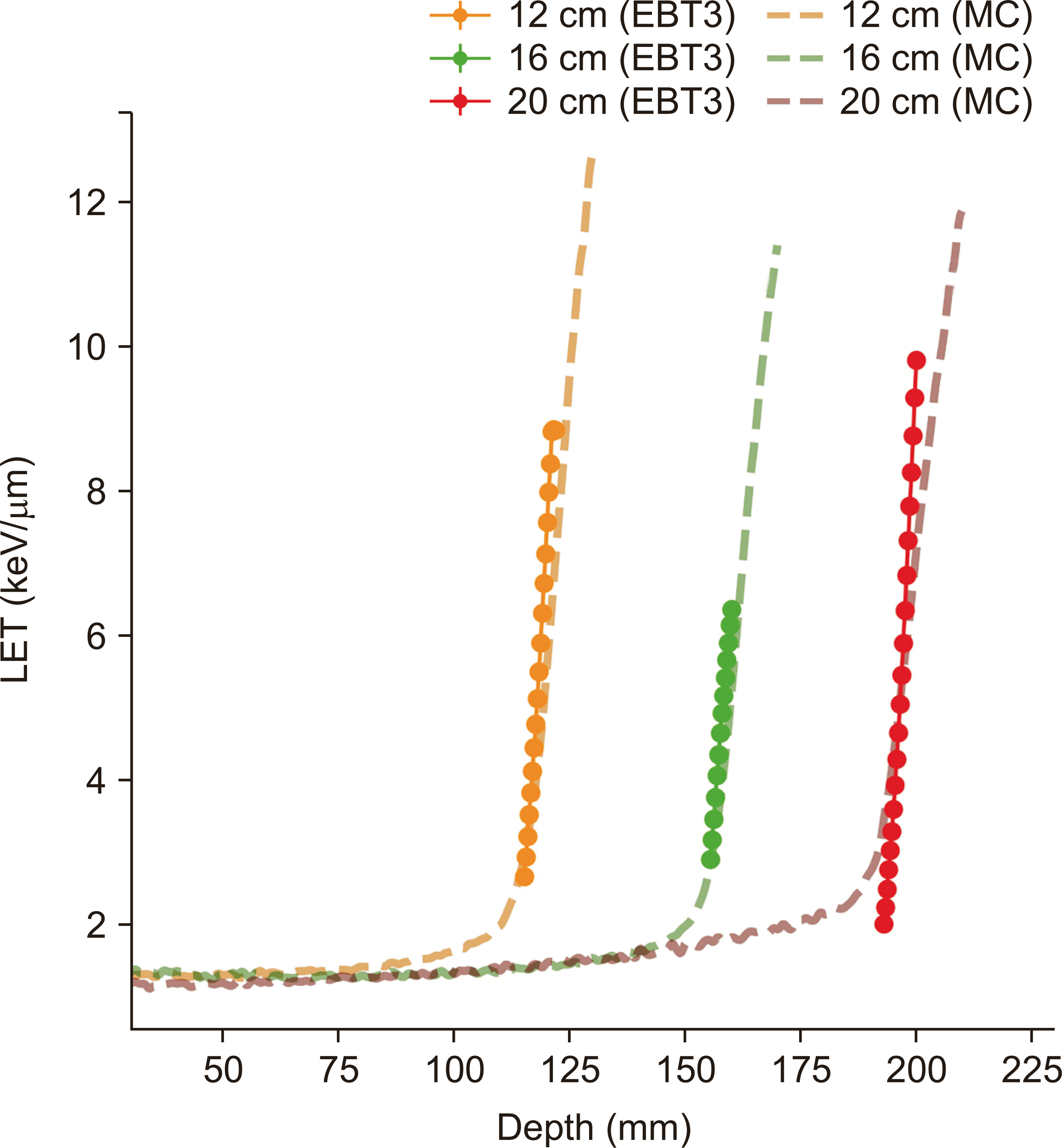
In this study, we assumed that the aspects of the quenching effect of the film and that of the scintillator are similar. However, the quenching effect of the film decreases from the distal fall-off region, observed in a previous study, and the quenching effect is less effective in the plateau region [
3]. Therefore, the LET is measured only from 70 percentage depth dose (PDD) region before the distal fall-off region on the EBT3 film. Because k
B must be determined by the observation before measuring the LET, it was estimated under the reference beam condition using the LET
d obtained by MC calculations. To obtain the kB, the corrected dose
D was measured by the ion chamber and the underestimated dose
Dunder was measured by the film; then, they were fitted to the LET obtained by MC calculations using the least χ
2 fitting method. The determined kB was applied to the other test beam cases.
2. MC calculation of LETd
The MC tool TOPAS was used to calculate the LET
d and physical doses [
14]. A study designed and calibrated the proton beam nozzle structure [
15]. Its beam parameters are determined by the converting algorithm (ConValgo) provided by the Proteus 235 manufacturer, IBA (Louvain-la-Neuve, Belgium). Nozzle simulation was performed to match the experimental environment as similar as possible. When primary protons were generated from the beam source, they passed through the nozzle structures, for example, beam scatterer and range modulator. The phantom material was set to G3_WATER with dimensions of 30×30×30 cm
3. The physical dose and LET were derived from the water phantom with a 1-mm interval and beam direction. The simulation dose profile distributions agreed with the measured dose profile from the Markus chamber (
Fig. 1).
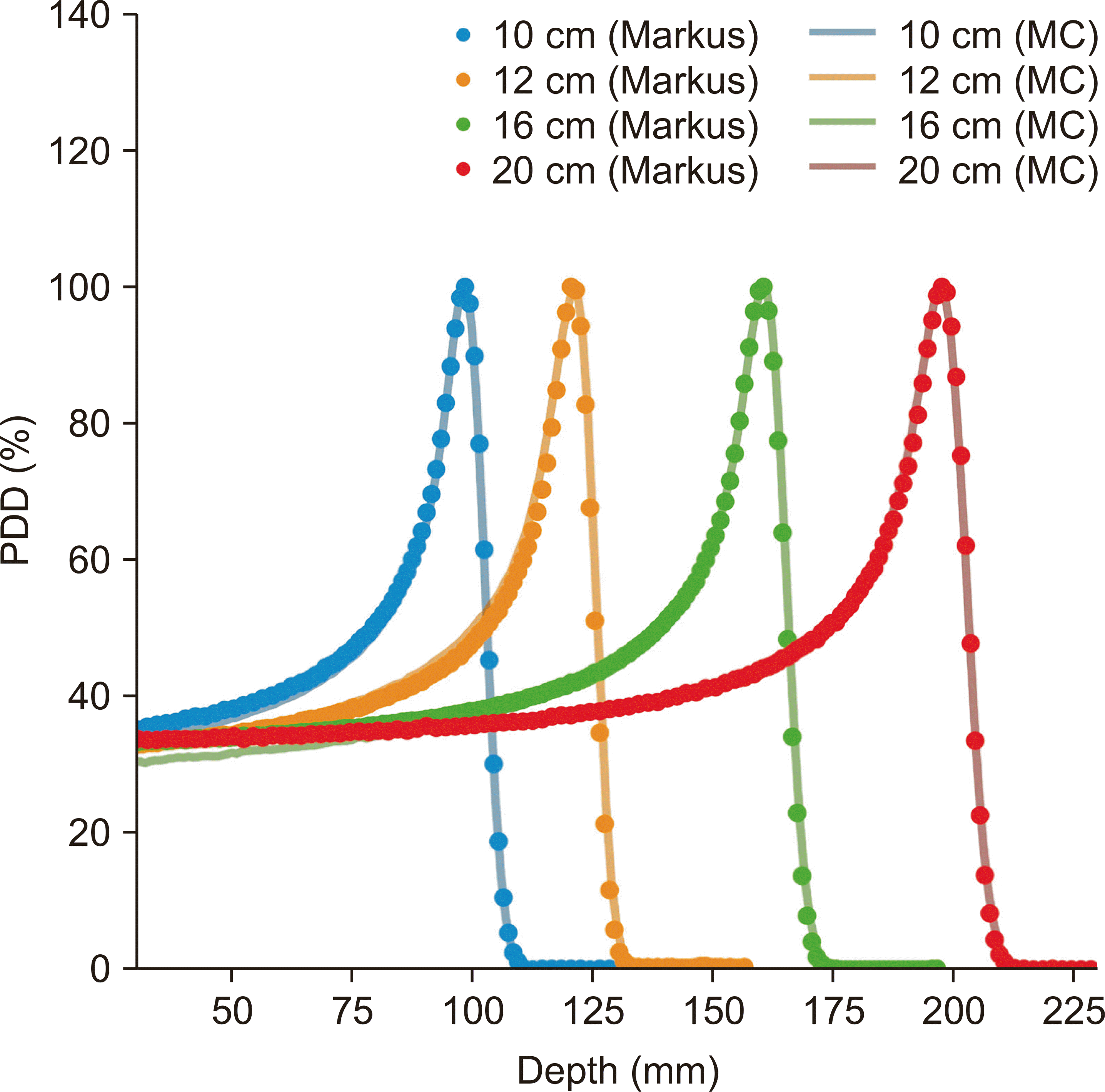 | Fig. 1Data and MC comparison of depth dose curves of 10-, 12-, 16-, and 20-cm water equivalent range beams measured by the Markus chamber (point plots) and MC (solid lines). MC, Monte Carlo; PDD, percentage depth dose. 
|
3. Radiochromic film measurement
Proton beams for the film measurement were irradiated by IBA Proteus 235 in NCCK. This machine provides energy proton beams ranging from 70 to 230 MeV with a full field size of 40×30 cm
2. The passive scattering mode was used for the irradiation. The pristine BP 10-cm proton beam in water was used as a reference beam, and the pristine BP 12-, 16-, and 20-cm proton beams in water were used as test cases. The detailed conditions are shown in
Table 1. Advanced Markus Chamber PTW 34045 was used as a reference chamber to determine these pristine BP ranges of proton beams and measured the PDD in the water phantom.
Table 1
Reference and test beam conditions in this study
|
Beam range |
Field size (cm×cm) |
Beam energy (MeV) |
Beam current (nA) |
|
Reference beam condition |
|
10 cm |
10×10 |
172 |
70 |
|
Test beam conditions |
|
12 cm |
10×10 |
162.14 |
70 |
|
16 cm |
10×10 |
185.00 |
70 |
|
20 cm |
10×10 |
205.2 |
70 |

EBT3 films (Lot 01042104) were irradiated in a water phantom and were fixed in the water phantom using a structure made by a 3D printer (M300 plus; Zotrax, Olsztyn, Poland). The structure comprises two plates with an open center, and the film was placed between the two plates. Then, the film was fastened by tightening plastic screws in the plates. A diagram of the structure is shown in
Fig 2b. Moreover, to avoid perturbations if the film was parallel to the proton beam path, the inside of the plates was placed on a 2.4° inclined plane [
8]. Because the film was tilted by the plates, the tilted depth was corrected as follows:
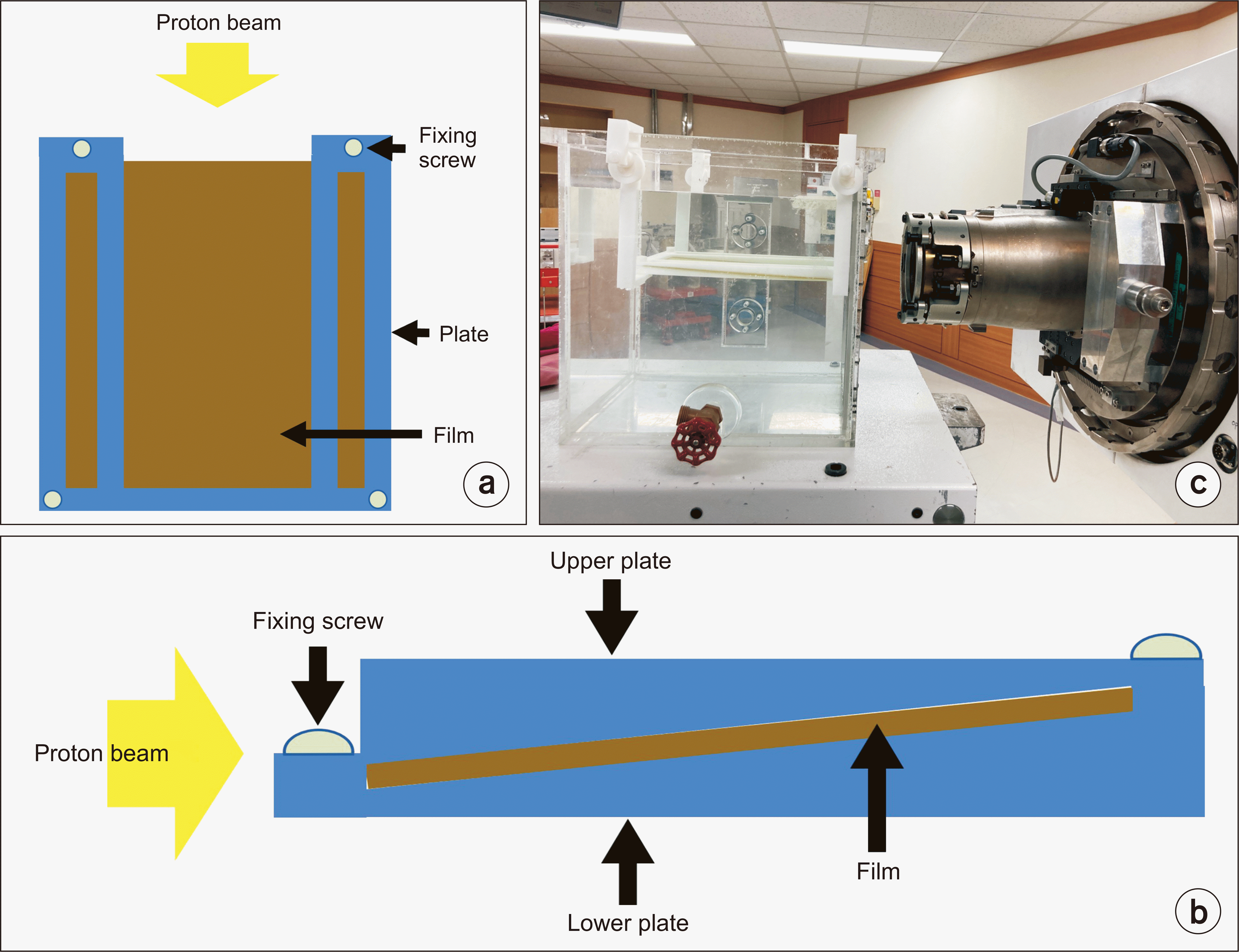 | Fig. 2(a) Top view of a schematic diagram of the measurement system, (b) side view of the 3D printed structure, (c) side view of the measurement system. 
|
where
dcorrected is the corrected depth and
d is the tilted depth. The entire measurement system is shown in
Fig. 2c.
The irradiated films were scanned using a commercial 48-bit-color scanner (Epson 10000XL scanner; Epson, Nagano, Japan), which has spatial resolution of 0.353 mm and estimated radiation doses through an image process. The scanned film images were analyzed using RIT (RIT, CO, USA). The only red channel was read even though the images consisted of three colors: red, green, and blue. The median filter with a kernel size of 5 was applied to remove impulse noise in the image. The pixel values given by the image process were converted using a calibration curves.
To convert the darkness of the pixel value to the radiation dose, the calibration curve was created using a proton beam having a pristine BP 13.89 cm in water. The EBT3 film was placed after a solid water phantom, which had a 3.135-cm water equivalent, and radiation doses were measured from 0 to 1,000 cGy using films. The interval of data points was interpolated by cubic-spline interpolation, which is constructed from third-order polynomials passing through two points, and the calibration curve was estimated (
Fig. 3).
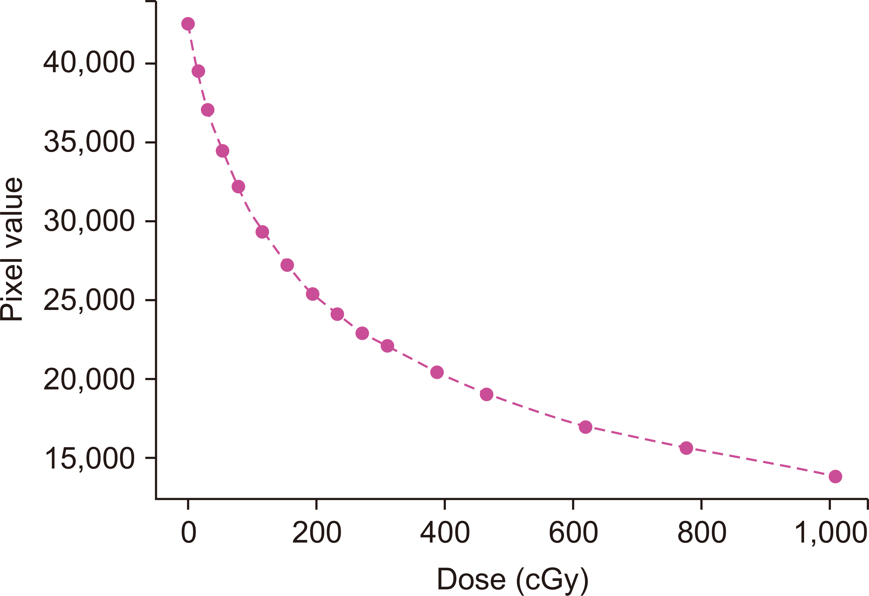 | Fig. 3EBT3 film calibration curve. Data points are measured behind the 3.135-cm solid water phantom. 
|


 PDF
PDF Citation
 Print
Print


 XML Download