This article has been
cited by other articles in ScienceCentral.
Abstract
Purpose
Proton therapy has been used for optimal cancer treatment by adapting its Bragg-peak characteristics. Recently, a tissue-sparing effect was introduced in ultrahigh-dose-rate (FLASH) radiation; the high-energy transmission proton beam is considered in proton FLASH therapy. In measuring high-energy/ultrahigh-dose-rate proton beam, Faraday Cup is considered as a dose-rate-independent measurement device, which has been widely studied. In this paper, the feasibility of the simply designed Faraday Cup (Poor Man’s Faraday Cup, PMFC) for transmission proton FLASH therapy is investigated.
Methods
In general, Faraday cups were used in the measurement of charged particles. The simply designed Faraday Cup and Advanced Markus ion chamber were used for high-energy proton beam measurement in this study.
Results
The PMFC shows an acceptable performance, including accuracy in general dosimetric tests. The PMFC has a linear response to the dose and dose rate. The proton fluence was decreased with the increase of depth until the depth was near the proton beam range. Regarding secondary particles backscatter from PMFC, the effect was negligible.
Conclusions
In this study, we performed an experiment to investigate the feasibility of PMFC for measuring high-energy proton beams. The PMFC can be used as a beam stopper and secondary monitoring system for transmission proton beam FLASH therapy.
Go to :

Keywords: Proton beam therapy, Faraday cup, FLASH
Introduction
In the 1930s, the proton cyclotron was developed to treat cancer using a proton beam. At present, more than 80 proton therapy facilities are considered in clinical operation or under construction [
1]. Korea National Cancer Center (KNCC) built a proton cyclotron in 2005, and the first proton beam therapy was performed in 2007 [
2].
Most conventional proton beam therapy uses the Bragg-peak (BP) characteristic, where the proton deposits most energy; thus, the targets are in the BP region. Recently, ultrahigh-dose rate radiotherapy (FLASH-RT) was introduced with interesting results, effective tumor control, and normal tissue protection [
3]. FLASH delivers an ultrahigh-dose-rate of more than 40 Gy/s. In proton FLASH-RT, the high-energy transmission proton beam is preferred in the current clinic system because of the limitation of beam control ability and simple treatment plan [
4]. Thus, a precise measurement for the high-energy/ultrahigh-dose-rate proton beam is required. A review paper showed the response of various charge-based detectors under a FLASH condition [
5]. Faraday Cup (FC) is a detector that is widely used for measuring charged particles. It can be used for proton beam measurement and proton therapy. Recent FCs are complex compared with other dosimetry devices because of their charge measurement principle: FC should contain a charged particle in its volume, making it with heavy metal such as copper or brass. In general, a clinical proton beam can penetrate a few centimeters in copper. In addition, the vacuum condition and additional electric/magnetic field are necessary to reduce the effect of secondary electrons produced while the proton penetrates the detector materials. However, even simplified vacuumless FC, namely, “Poor Man’s Faraday Cup” (PMFC), showed comparable results in the previous study [
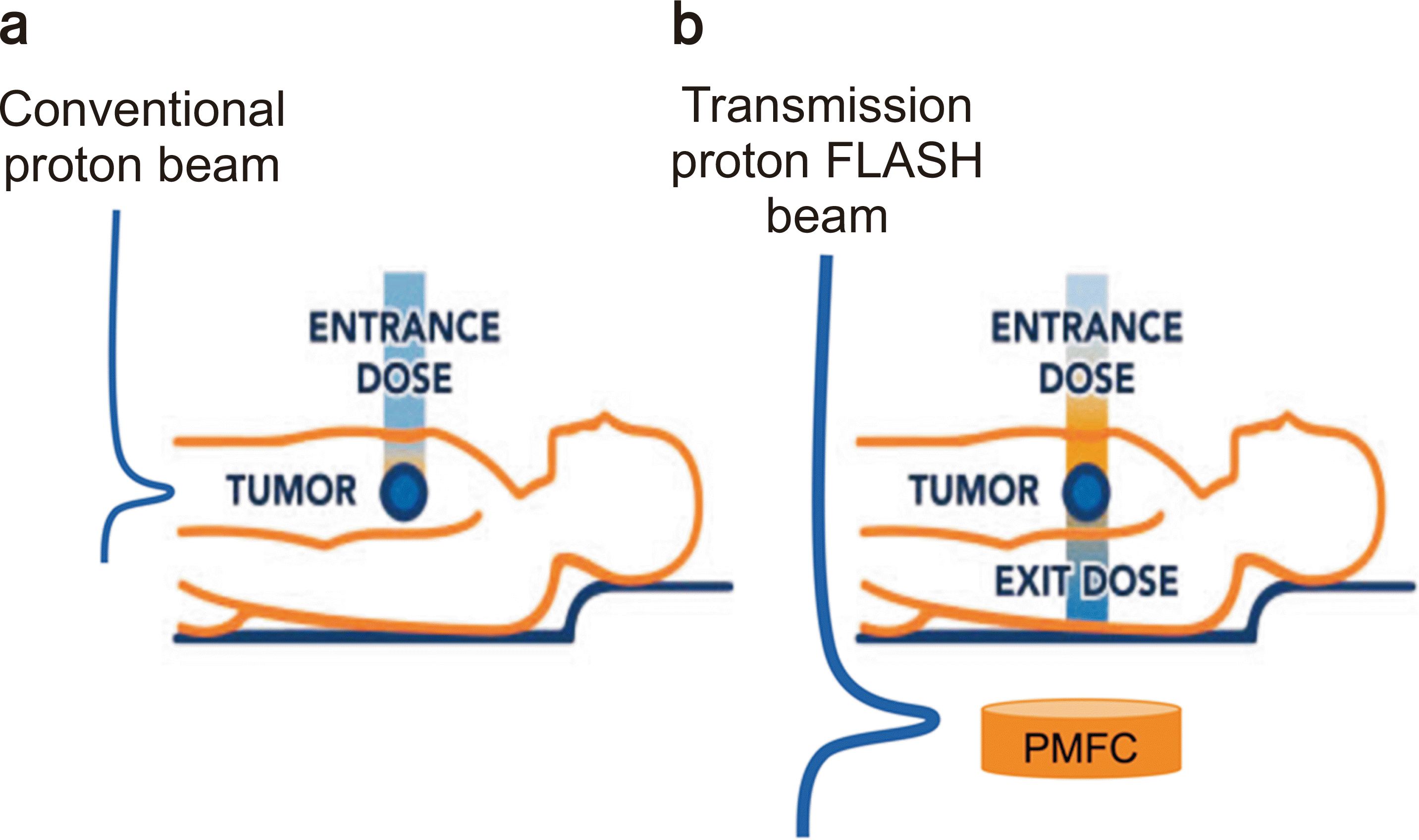
6]: within 1% to 5% differences from the traditional type of FCs. Such a study was performed in conventional low-dose rate conditions. We performed the experiment at a high-dose-rate condition for PMFC for the following purposes: (1) Beam stopper for transmission proton beam; (2) A real-time secondary beam monitoring device for safety and postevaluation system. We tested the feasibility of the PMFC for transmission proton FLASH therapy. The concept drawing is shown in
Fig. 1.
 | Fig. 1
|
Go to :

Materials and Methods
1. Proton beam
The proton beam is created in a cyclotron PROTEUS 235 proton therapy machine (IBA, Louvain-La-Neuve, Belgium) built at KNCC. The maximum energy of the proton is 230 MeV. It has three nozzles: one fixed passive scattering, one rotation passive scattering, and one pencil beam scanning nozzle. The experiment was performed in a fixed nozzle room, and the range of 30 cm pristine BP proton beam was used for this study. In minimizing the loss of proton flux, most of the nozzle components were removed from the proton beam path. The proton beam condition is summarized in
Table 1.
Table 1
Reference proton beam conditions in this study
Range at nozzle
(energy) |
First scatterer |
Second scatterer |
Range modulation wheel |
Beam current modulation |
Snout |
|
30 cm (217.73 MeV) |
Removed |
Removed |
Removed |
None |
Ring-shaped open block
(10 cm diameter) |

2. Measurement devices
In principle, FC measures the total charge by counting the absorbed charged particles in the volume. The design of PMFC is the same as the “EMC-2” in the reference paper [
6]. PMFC has a 20 cm diameter to contain laterally scattered protons. The brass block is wrapped in a 0.13 mm Kapton insulator to reduce the charge induced by outer air. For the signal readout, the triaxial TNC cable is connected to the brass block and ground to minimize noisy environmental backgrounds. The IBA Dose 1 electrometer was used for current and charge measurement. A plane-parallel ion chamber, namely, PTW Advanced Markus, was used as the reference chamber for dose, dose rate measurement, and backscatter effects.
3. Experiment setup
The PMFC was located 30 cm behind the isocenter position, and solid–water phantoms were placed in front of the PMFC. Advanced Markus was located between PMFC and solid–water phantoms in the beam path. The setup is shown in
Fig. 2. This setup allowed us to simultaneously measure the total charge and current signal from PMFC and Advanced Markus. We tested the PMFC performance on the basis of general dosimetric characteristics of high-energy/high-dose-rate transmission proton beam.
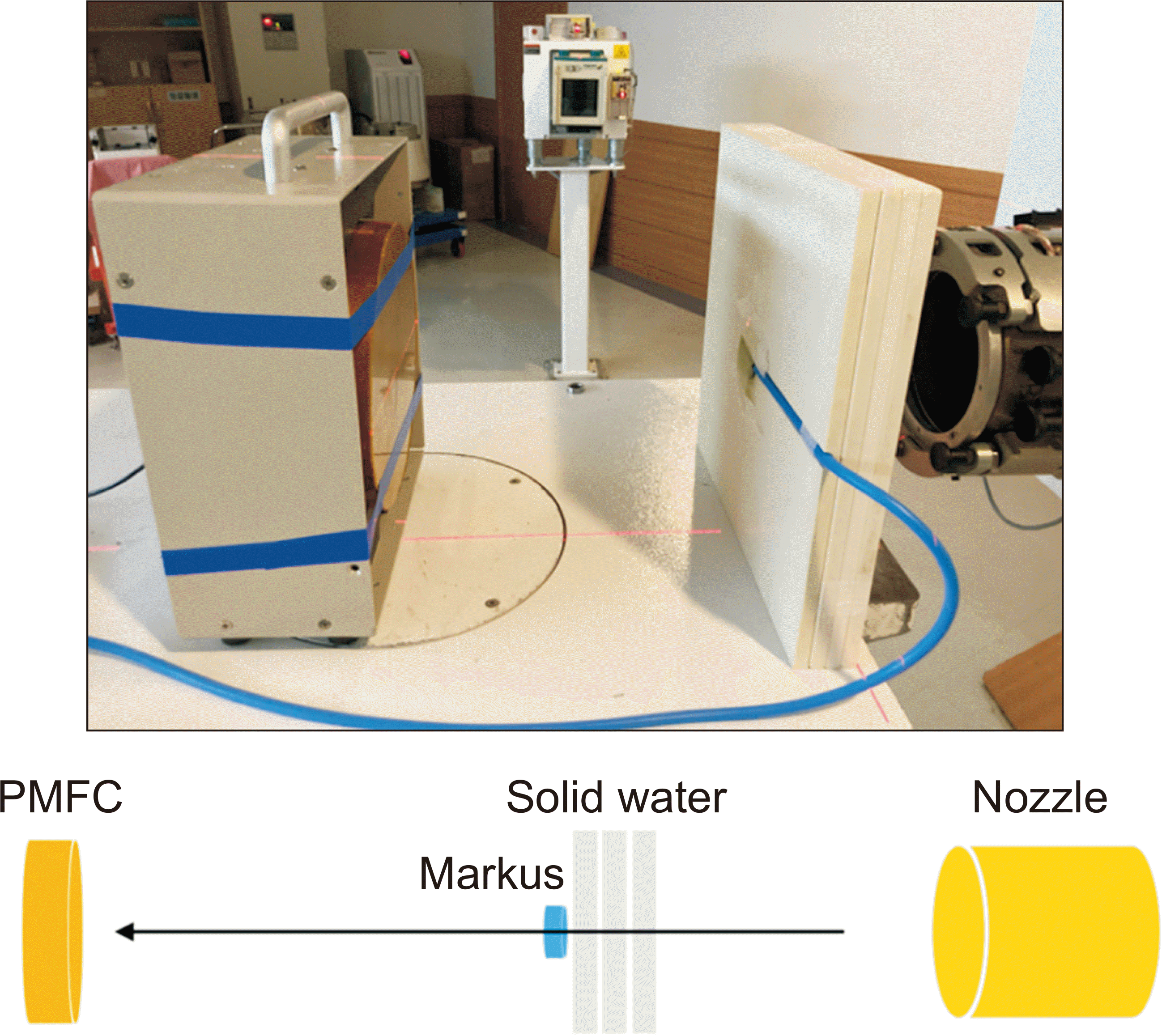 | Fig. 2Setup for Poor Man’s Faraday Cup (PMFC) and Advanced Markus ionization chamber. 
|
1) Dose and dose rate measurement
In measuring the dose, the high-energy proton beam penetrates a 3-cm solid–water phantom and Advanced Markus, and then it is finally absorbed in PMFC. We recorded signals from PMFC and Advanced Markus at different monitor units (MUs): 200, 400, 600, 800, 1,000, and 2,000 MU. The dose rate is measured similarly. We recorded the current signal from PMFC and Advanced Markus, while the proton beam was delivered at different cyclotron currents (nA): 10, 50, 100, 200, and 300. Finally, the recorded charge and current signal from Advanced Markus were converted into an absorbed dose/dose rate adopting TRS-398-based calibration [
7].
2) Range measurement
We measured a proton range using the total charge recorded in the Advanced Markus and PMFC with increasing depth of solid phantoms: 3, 5, 7, 10, 15, 20, 25, 27, 28, 28.5, 29, 29.3, 29.5, and 30 cm. FC is a device that counts the total number of absorbed protons independent of energy. If protons are fully absorbed in the volume, then the Advanced Markus shows a different aspect, which measures the ionization ability of charged particles.
3) Effect of backscatter particle measurement
Measuring the dose from backscatter particles is important because it can increase the dose to the near patient in transmission proton therapy. We evaluated the potential backscatter effect of PMFC. The PMFC was placed after the Advanced Markus at 0, 5, 10, 20, and 30 cm back, and the signal difference recorded in Advanced Markus was checked.
Go to :

Results
The thickness of PMFC is important for the measurement of total charge because it cannot measure the correct charge if the proton penetrates the PMFC volume. In optimizing the thickness of the PMFC, the Geant4 Monte–Carlo (MC) simulation was used. The MC simulation results indicate that the 6.4-cm-thick brass block can contain more than 99.99% of the proton of 230 MeV (
Fig. 3).
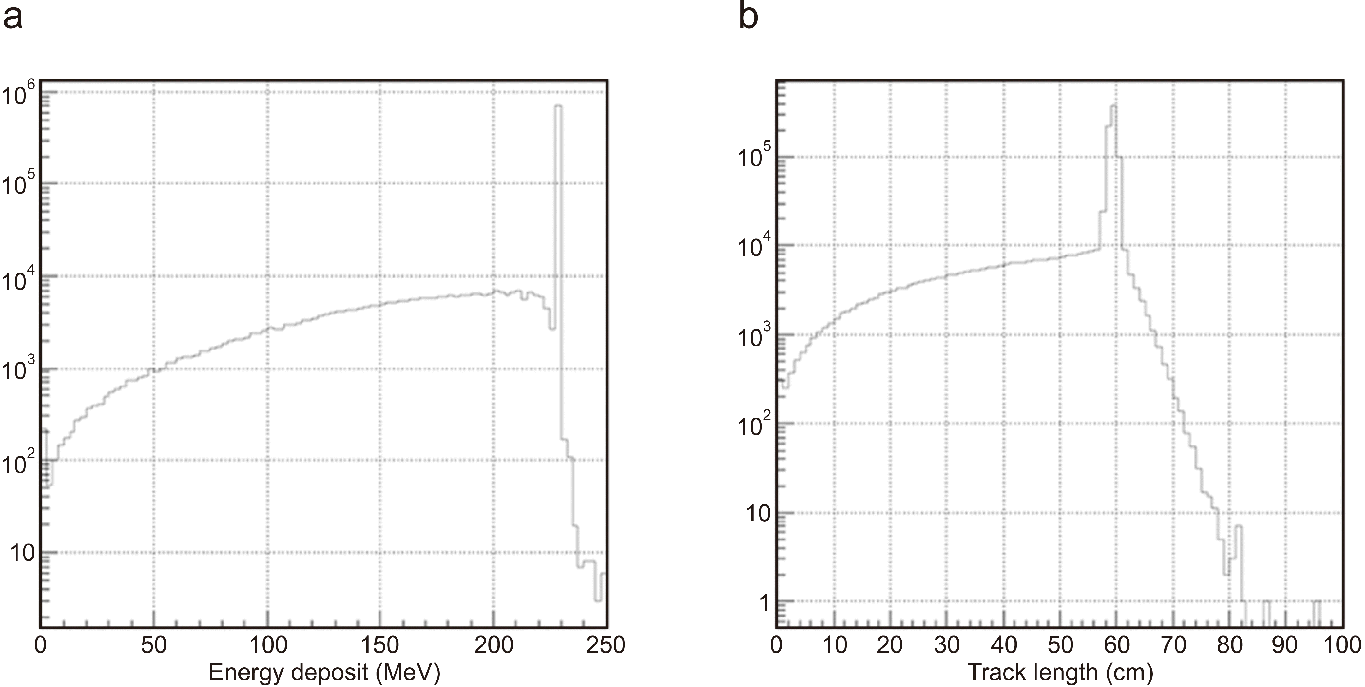 | Fig. 3Geant4 Monte–Carlo simulation: proton energy deposit (a) and track length (b) in Poor Man’s Faraday Cup (PMFC). 
|
The PMFC was stable at room temperature of 20°C and pressure of 1,000 kPa; the maximum deviation of the noise was a few pico-Amperes, which is less than 0.1% of signal output.
1. Dose and dose rate measurement
Fig. 4 shows the experimental result for the different doses delivered to the PMFC. The proton beam is incident to the center of the Markus chamber and PMFC. The dose and dose rate are converted from the total charge/current signal recorded in Advanced Markus. PMFC shows a linear response to the increased dose and dose rate up to the FLASH condition (≥40 Gy/s). Standard deviation is calculated from three independent measurements on each measurement point and assigned as an error bar, but it is negligibly small.
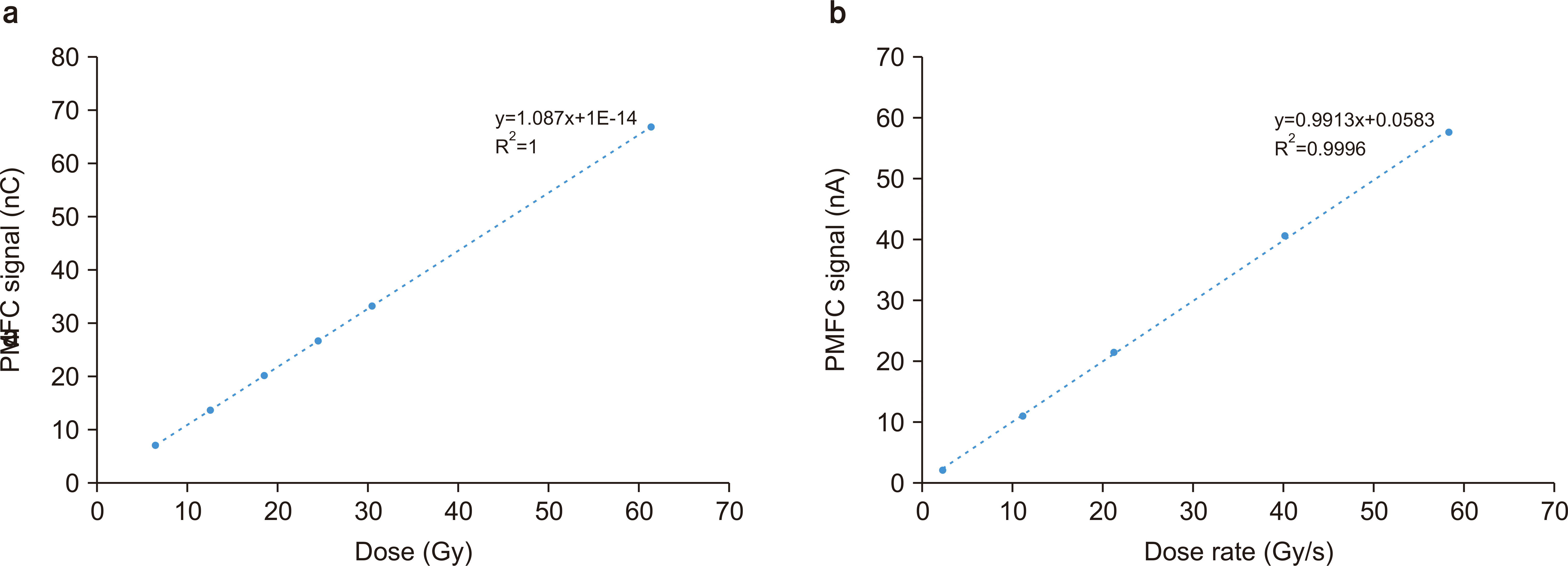 | Fig. 4Poor Man’s Faraday Cup (PMFC) signal linearity check for proton beam dose (a) and dose rate (b). 
|
2. Range measurement
As the thickness of the solid–water phantom increase, the signal gradually decreases because of the proton attenuation in the solid–water phantom. Near the BP region, the PMFC signal drops sharply. The range is defined as the depth at which the fluence reaches 50%. The results are shown in
Fig. 5. Error bars on the points are the standard deviation of three independent measurements. The standard deviation of PMFC is relatively bigger than Advanced Markus because the signal is sensitive to setting, and it fluctuates while adding solid–water phantoms in front of PMFC.
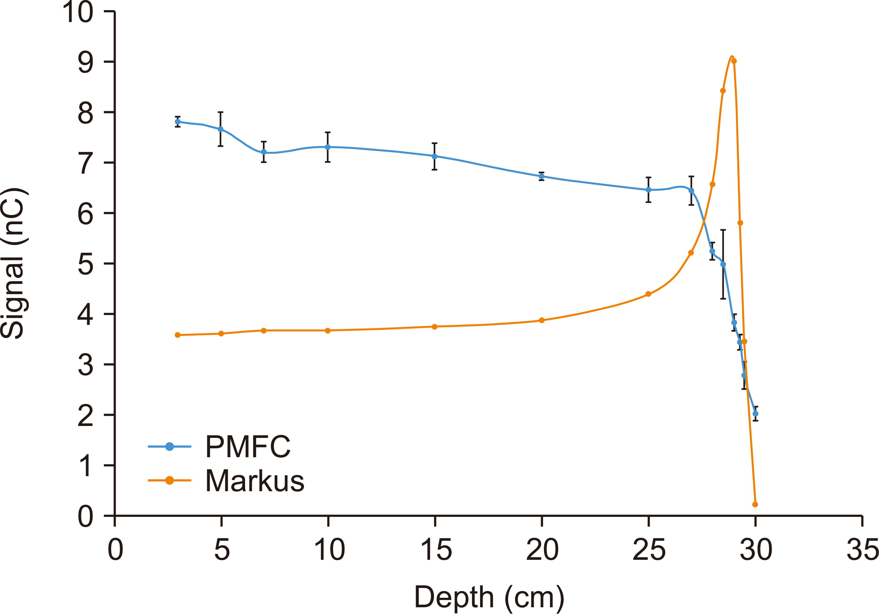 | Fig. 5Range measurement using Poor Man’s Faraday Cup (PMFC) and Advanced Markus ion chamber. 
|
3. Evaluation of the backscatter effect
Fig. 6 shows a relative signal recorded in the Advanced Markus for various gaps using PMFC. We expected a dose increasement because of the backscatter particles from the PMFC, but the result indicates a maximum 0.3% effect, which is negligible. Error bars on the points are the standard deviation of three independent measurements, which is also negligibly small.
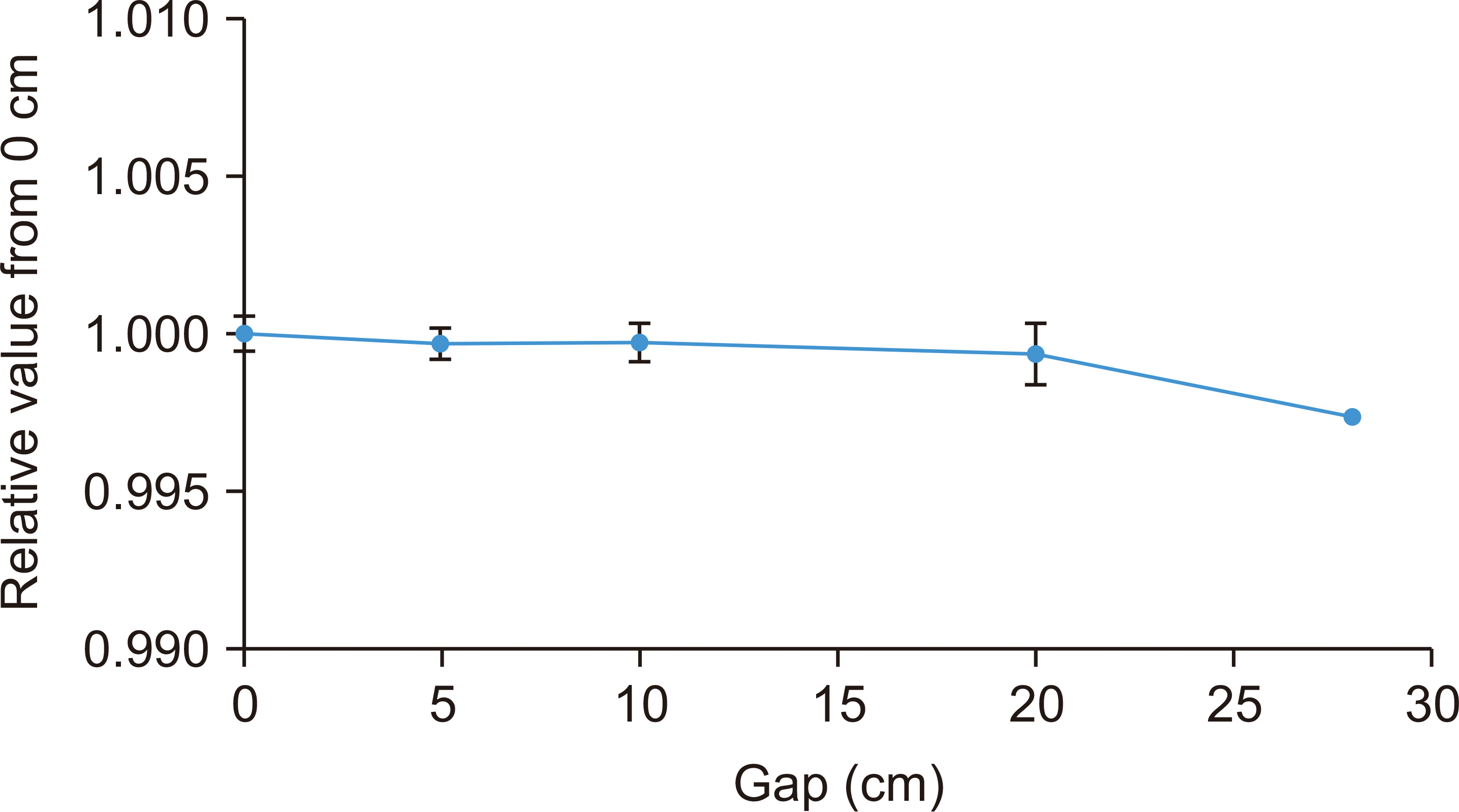 | Fig. 6Relative signal based on the gaps between Poor Man’s Faraday Cup (PMFC) and Advanced Markus. 
|
4. Measurement of beam width in the proximal region
While penetrating the material, the beam width increased because of scattering. Since transmission FLASH therapy aims to treat cancers in the proximal region of the proton beam, we measured a full-width-half-maximum of the proton beam as a function of depth using Gafchromic EBT3 film [
8]. The result is shown in
Fig. 7. The beam width in the proximal region increased by 25% while penetrating 25 cm depth. This result indicates that the 20 cm diameter of PMFC can cover the field size of the proton beam to approximately 15 cm.
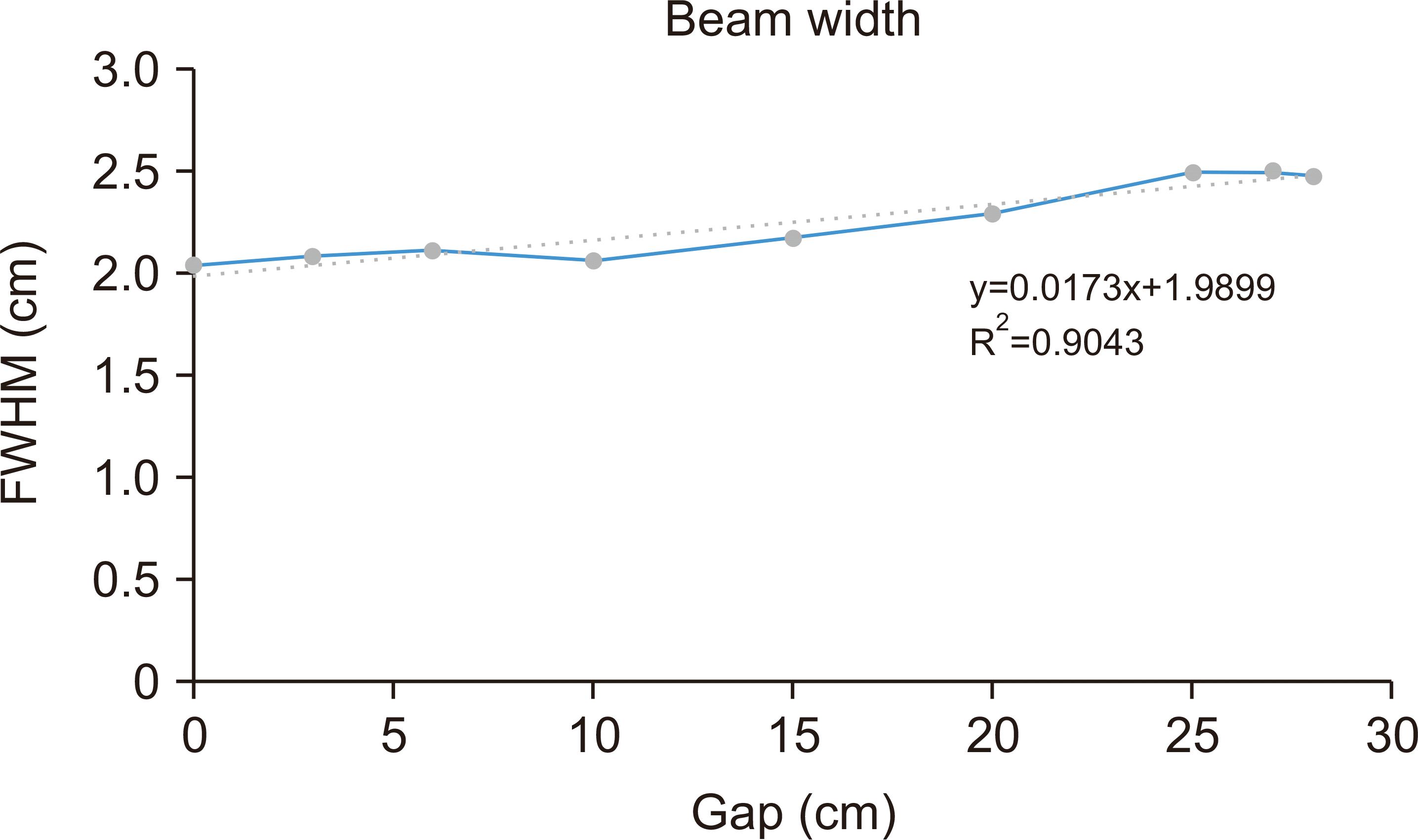 | Fig. 7Full-width-half-maximum (FWHM) of the proton beam as a function of depth. 
|
Go to :

Discussion
The recent FC is highly accurate, but it is hard to use because of its complex structure that includes a vacuum and electromagnetic system. The PMFC is a simple and cheap device, which allows us to easily fabricate and use it while keeping acceptable performance. In addition, the flat and wide plane geometry of PMFC is suitable to use in the transmission proton FLASH therapy to contain the scattered proton beam. However, the application of this device is hindered because of the limited FLASH beam control, the small field size of proton FLASH beam, and high activation level after FLASH beam irradiated to material.
Go to :

Conclusions
Proton FLASH therapy is an interesting topic in the radiotherapy field. Although the biological mechanism of the normal tissue-sparing effect of FLASH therapy remains unclear, many studies for FLASH-RT are in progress. This study was performed to evaluate the feasibility of PMFC in transmission proton beam FLASH therapy. The experimental data show the potential of PMFC. As a beam stopper, the 6.4-cm-thick brass block is enough to contain 230 MeV proton. As a real-time secondary monitoring device for the safety and postevaluation system, PMFC showed an acceptable performance, including accuracy.
Go to :

Acknowledgments
This research was supported by the National Research Council of Science & Technology (NST) grant by the Korea government (MSIT, No. CAP22041-101). This research was also supported by Basic Science Research Program through the National Research Foundation of Korea (NRF) funded by the Ministry of Education (NRF-2020R1A6A3A13052170).
Go to :

Notes
Go to :

References
1. Particle Therapy Co-Operative Group. Facilities in operation [Internet]. Particle Therapy Co-Operative Group,;[place unknown]: Available from:
https://www.ptcog.ch/. cited 2022 Jul 20.
2. Lee SB. 2020; Proton therapy review: proton therapy from a medical. Prog Med Phys. 31:99–110. DOI:
10.14316/pmp.2020.31.3.99.

4. Wei S, Lin H, Choi JI, Press RH, Lazarev S, Kabarriti R, et al. 2022; FLASH radiotherapy using single-energy proton PBS transmission beams for hypofractionation liver cancer: dose and dose rate quantification. Front Oncol. 11:813063. DOI:
10.3389/fonc.2021.813063. PMID:
35096620. PMCID:
PMC8794777.

5. Ashraf MR, Rahman M, Zhang R, Williams BB, Gladstone DJ, Pogue BW, et al. 2020; Dosimetry for FLASH radiotherapy: a review of tools and the role of radioluminescence and Cherenkov emission. Front Phys. 8:328. DOI:
10.3389/fphy.2020.00328.

6. Cascio EW, Gottschalk B. 2009. A simplified vacuumless Faraday cup for the experimental beamline at the Francis H. Burr proton therapy center. Paper presented at: 2009 IEEE Radiation Effects Data Workshop; 2009 Jul 20-24; Quebec, Canada. DOI:
10.1109/REDW.2009.5336294.

7. International Atomic Energy Agency (IAEA). 2000. Absorbed dose determination in external beam radiotherapy. IAEA;Vienna: p. 398. DOI:
10.3389/fphy.2020.00328.
8. Vadrucci M, Esposito G, Ronsivalle C, Cherubini R, Marracino F, Montereali RM, et al. 2015; Calibration of GafChromic EBT3 for absorbed dose measurements in 5 MeV proton beam and (60)Co γ-rays. Med Phys. 42:4678–4684. DOI:
10.1118/1.4926558. PMID:
26233195.

Go to :


 PDF
PDF Citation
 Print
Print


 XML Download