

 PDF
PDF Citation
 Print
Print


INTRODUCTION
The accurate description of the dental and periapical tissues and the root canal system is essential for the diagnosis, treatment planning and follow-up in endodontics. The implementation of imaging techniques that allow precise observation of these structures, in terms of sensitivity and specificity has been a constant in the evolution of endodontic therapy [1]. Although currently, conventional 2-dimensional (2D) periapical imaging used in conjunction with clinical evaluation continues to be the standard, multiple limitations such as compression of 3-dimensional (3D) anatomy, geometric distortion, anatomical noise and temporal perspective—inherent in the nature of 2D imaging, and which can directly impact the outcome of endodontic therapy—have been well established in the literature [12].
The possibility of navigating the conventional volumetric planes: axial, sagittal, and coronal (view of 3D structures) and multiple alternative planes—which at the same time translates into greater sensitivity for the identification of endodontic pathologies and conditions—has allowed cone-beam computed tomography (CBCT) to acquire a predominant role in the analysis of clinical cases in which 2D images do not offer the necessary information for an adequate endodontic approach [3]. Likewise, the widespread use of CBCT in endodontics has allowed the development of multiple technological tools for the analysis and interpretations of CBCT scans. 3D volume interpretation must be approached systematically and reproducibly to improve precision in terms of diagnosis and planning of endodontic clinical procedures and thus reduce the probability of inherent errors. To date, multiple studies have evaluated the applications of CBCT in terms of diagnosis, treatment, and outcome in endodontic therapy. However, little has been published about CBCT interpretation. This comprehensive review of the literature provides an updated overview of the theoretical concepts and elements of interpretation of the CBCT scan in endodontics based on specific technical considerations that enable accurate diagnosis and treatment planning. Additionally, the contents and rationale for reporting 3D endodontic imaging and cutting-edge therapeutic options based on CBCT are presented.
RADIOLOGICAL ASPECTS OF CBCT
Obtaining the image
The generation of 3D images requires a tomograph, also called a scanner (CT scanner), which needs specific hardware, composed primarily of a rotating C-arm (Gantry), that hosts the X-ray source and the detector (converts the X-rays into the electrical signal) [4]. During the scan, a collimated, fan-shaped X-ray beam is directed through the region of interest, across the maxillofacial study area. The attenuated photons strike the scintillation detector on the opposite side [4].
Ideally, the arm rotates 360° around the patient (but can vary from 180 to 720°) with scan times between 10 and 40 seconds. Since the X-ray beam is pulsed, the real exposure period is 2–5 seconds, resulting in as many as 580 “mini-exposures” or “projection images” throughout the scan. A pixel matrix comprising 262,144 (5122) pixels is produced for each mini-exposure [3]. The resulting dataset is then computer-aided reconstructed in 3D pixels (voxels), which account for around 100 million voxels (5123). The resolution can be improved by increasing the number of pixels per matrix (from 5122 to 1,0242), which also increases irradiation exposure [3].
During the reconstruction process, each observation unit is assigned a value on a predefined grey scale, according to the attenuation of the material on each of its axes (X, Y, and Z). Subsequently, the values are integrated with the use of mathematical algorithms in specific software that allows volumetric (3D) observation on a computer screen [34].
Observation planes
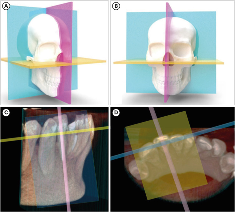
The CBCT scans enable 3D spatial navigation of the anatomical structures in the 3 volumetric planes. The sagittal plane (vertical plane parallel to the median plane, which runs/divides from mesial to distal or left to right), coronal plane (vertical plane, perpendicular to the sagittal plane, anteroposterior observation), and axial plane (perpendicular to the sagittal and coronal planes, cephalocaudal observation) (Figure 1A and 1B) [5]. Likewise, the reconstructed data allows observation in alternative planes—oblique planes—which are very useful in endodontics, since they allow the visualization of anatomical structures according to the longitudinal axis of the tooth (Figure 1C and 1D).
Conditions for the acquisition
1. Voxel
In CBCT, a voxel is defined as the smallest viewable part, represented by a cube, which the digital 3D image data can be divided into (the smallest 3D element of the volume). Unlike the pixel with only x and y coordinates, the voxel also has the z coordinate, providing depth. For CBCT, voxels are isotropic, and their size is directly related to image quality and reconstruction time [6]. The detector’s matrix and pixel size serve as the primary determinants of the nominal voxel size in a CBCT image. Detectors are produced with varying active sensor areas (matrix size, which in turn depends on the total number of pixels). Pixel size ranges from less than 20 µm to 70 µm [7]. The spatial resolution of CBCT devices is linked to the physical pixel size, the reconstruction technique applied and the grey-level resolution among other factors [8]. The smaller the size of the pixel, the higher the maximally attainable resolution. However, detectors with smaller pixels capture fewer X-ray photons, therefore generating more noise in the image. Consequently, to obtain a better resolution, it is necessary to use higher doses to compensate for the image-noise ratio [78]. The selection of the voxel size must be made according to the initial diagnostic impression, since anatomical structures or pathological findings of sizes smaller than the selected voxel size may not be evident in the tomographic image (Figure 2) [91011].
Figure 2
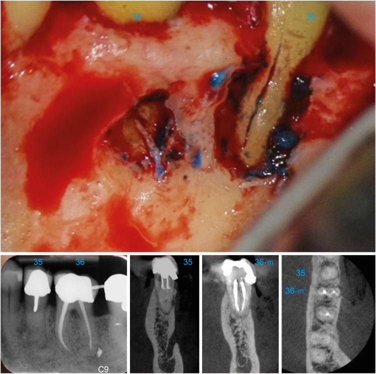
The ability of cone-beam computed tomography (CBCT) to identify vertical fractures is affected by several factors: (i) size of the fracture line < 80 µ and/or smaller than the CBCT voxel size. (ii) Noise/artifact in the image related to endodontic treatment, intra-radicular posts and ceramic/metallic restorations. (iii) Noise/artifact produced by patient movement during the CBCT scanning [11]. In the aforementioned clinical case, the CBCT revealed a relatively localized pattern of bone loss on the coronal plane (buccal area of the mandibular molar), which is a very typical tomographic finding in patients in which vertical fracture is suspected [11].
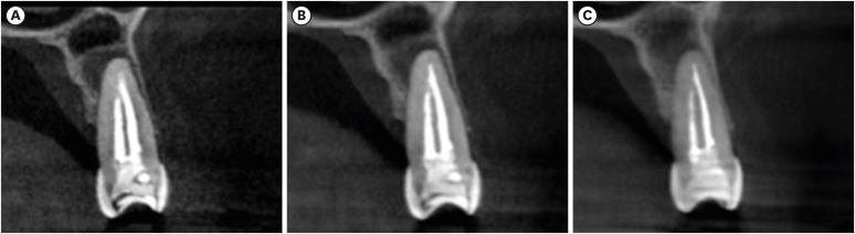
Comparatively, smaller voxel sizes are related to higher resolution, higher radiation dose, and longer reconstruction time, but also a greater possibility of occurrence of artifacts [12]. Voxel values between 76 μm to 300 μm are therefore recommended for endodontics, given the structural characteristics of the dentine pulp complex and periapical tissues (Figure 3) [10].
2. Field of view (FOV)
The FOV refers to the anatomical area—measured in mm—that will be included in the volume of data or the area that will be subjected to radiation [910]. The FOV’s or scan volume’s dimensions are principally influenced by the detector’s size and shape, the beam’s projection geometry, and the beam collimation capability [10]. The selection of the given FOV will depend on the clinical characteristics of the studied case (Figure 4) and the tomograph’s characteristics [910].
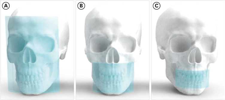
Figure 4
Field of view (FOV) sizes. (A) Large FOV (78–150 mm). (B) Medium FOV (61–78 mm). (C) Small FOV (≤ 50 mm).
In general, the smaller the scanning volume, the higher the spatial resolution of the image, and the lower the radiation dose and the reconstruction time needed, therefore, small FOVs are recommended for diagnosis and treatment in endodontics, as they reduce the volume of the tissues being exposed to radiation and also the ray dispersion, favorably impacting the quality of the images [910]. Although most authors have suggested small FOVs for endodontic purposes, specific suggestions have also been given according to the specific requirement (Table 1, Figure 5) [13141516171819202122].
Table 1
Recommendations for interpreting various endodontic situations
| Procedure | Suggested FOV | Recommendations |
|---|---|---|
| Endodontic diagnosis | Small FOV | • A small FOV CBCT examination should only be considered if 2-dimensional conventional radiography does not provide enough information for a confident diagnosis and the additional information from reconstructed 3-dimensional images is likely to help with diagnosis and treatment planning and/or improve clinical management [13]. |
| CBCT diagnostic image with the presence of highly radiopaque objects | Small FOV | • In order to prevent scanning locations prone to beam hardening, limit the FOV and modify the arch selection. |
| • The beam hardening and scattering impacts brought on by a metallic structure can be lessened using the metal artifact-reducing algorithm [14]. | ||
| Diagnosis of vertical root fractures and cracks | Small FOV | • Although even the smallest voxel size may not have enough spatial resolution for diagnosing vertical root fractures, the CBCT scan can reveal typical patterns of peri-radicular bone loss associated with vertical fractures [13]. |
| • As long as there are no high-density objects in the region of interest, small FOV high-resolution protocols may be effective in detecting fine endodontic structures such as cracks [15]. | ||
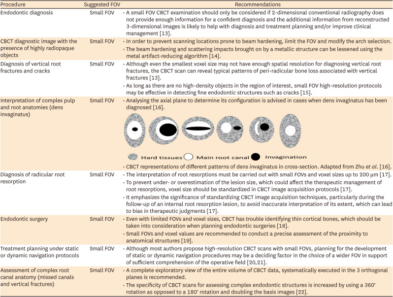
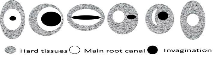
| Interpretation of complex pulp and root anatomies (dens invaginatus) | Small FOV | • Analysing the axial plane to determine its configuration is advised in cases when dens invaginatus has been diagnosed [16]. |
|
||
| • CBCT representations of different patterns of dens invaginatus in cross-section. Adapted from Zhu et al. [16]. | ||
| Diagnosis of radicular root resorption | Small FOV | • The interpretation of root resorptions must be carried out with small FOVs and voxel sizes up to 200 μm [17]. |
| • To prevent under- or overestimation of the lesion size, which could affect the therapeutic management of root resorptions, voxel size should be standardized in CBCT image acquisition protocols [17]. | ||
| • It emphasizes the significance of standardizing CBCT image acquisition techniques, particularly during the follow-up of an internal root resorption lesion, to avoid inaccurate interpretation of its extent, which can lead to bias in therapeutic judgments [17]. | ||
| Endodontic surgery | Small FOV | • Even with limited FOVs and voxel sizes, CBCT has trouble identifying thin cortical bones, which should be taken into consideration when planning endodontic surgeries [18]. |
| • Small FOVs and voxel values are recommended to conduct a precise assessment of the proximity to anatomical structures [19]. | ||
| Treatment planning under static or dynamic navigation protocols | Small FOV | • Although most authors propose high-resolution CBCT scans with small FOVs, planning for the development of static or dynamic navigation procedures may be a deciding factor in the choice of a wider FOV in support of sufficient comprehension of the operative field [2021]. |
| Assessment of complex root canal anatomy (missed canals and vertical fractures) | Small FOV | • A complete exploratory view of the entire volume of CBCT data, systematically executed in the 3 orthogonal planes is recommended. |
| • The specificity of CBCT scans for assessing complex endodontic structures is increased by using a 360° rotation as opposed to a 180° rotation and doubling the basis images [22]. |
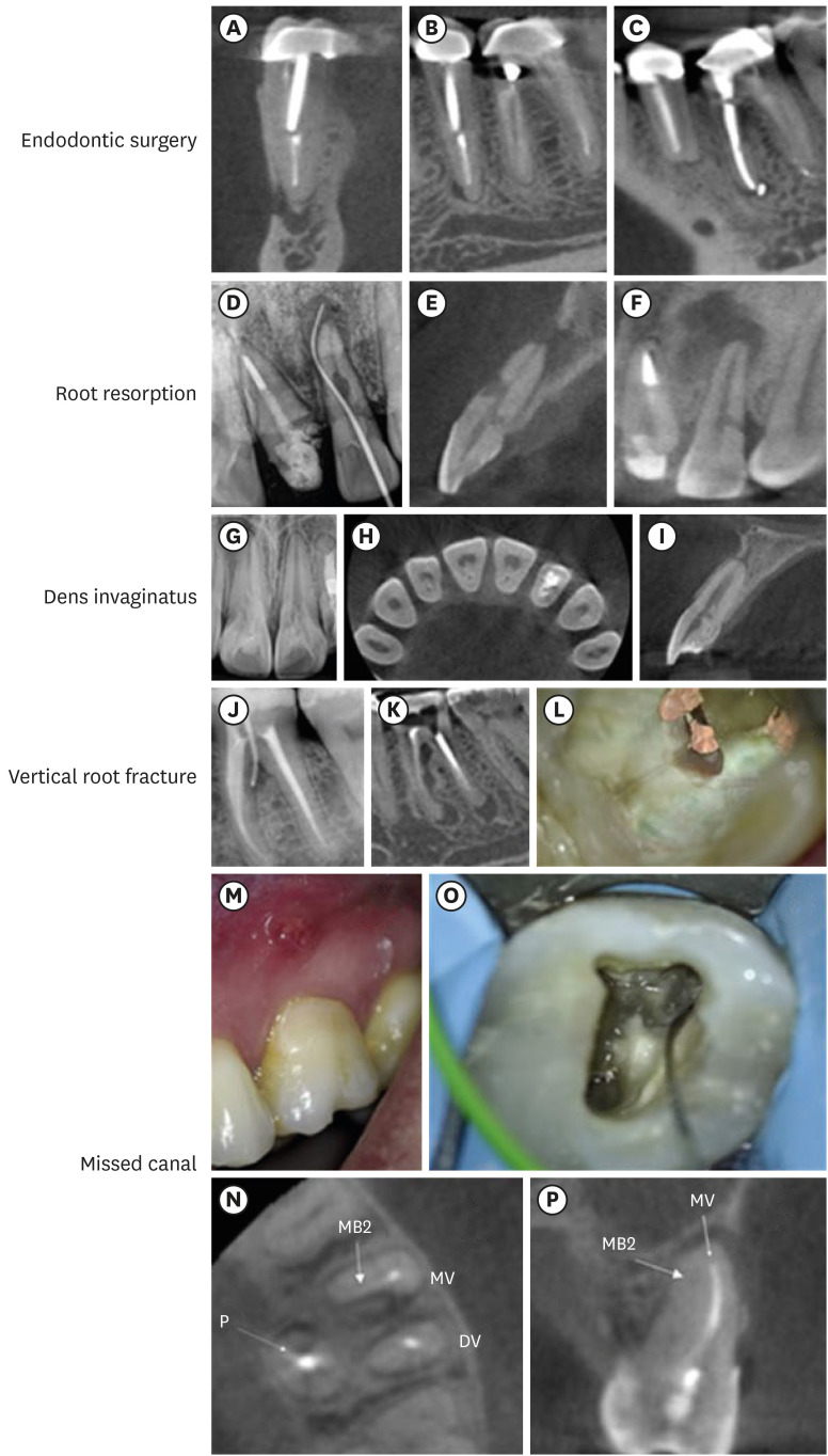
Figure 5
Clinical applications of cone-beam computed tomography (CBCT) in endodontics. (A-C) Endodontic surgery: multiple navigation planes enable the planning of surgical procedures while preserving the integrity of anatomical structures (mental nerve) nearby the operative site. Root resorption: the perforating aspect of the internal root resorption (E) may be seen in the sagittal plane thanks to 3-dimensional navigation. Neither periapical radiography (D) nor the examination of the coronal plane (F) can yield this finding. Dens invaginatus: (G) initial periapical radiograph suggesting the possibility of an atypical tooth anatomy. The classification (type 1) of the dens invaginatus can be determined by navigating the axial (H) and sagittal planes (I) of the CBCT scan. The sagittal plane (I) enables the relationship between the invagination and the main root canal to be confirmed. Type-I dens invaginatus without connection to the main canal is seen at the cervical level. Vertical root fracture: (J) initial endodontic fistulography. Vertical root fractures typically exhibit dehiscence-type bone defects that are seen on the CBCT in conjunction with a single, narrow periodontal pocket (K). However, clinical validation of these results is required (L). Missed canals: (M) endodontic sinus tract suggesting endodontic failure. Axial and sagittal planes (N, O) confirm the presence of an MV2 missing canal. (P) Clinical validation of tomographic findings.
Technical characteristics: dosages and specific requirements for endodontic
Due to the occurrence of deterministic and stochastic effects caused by the interaction of X-rays with biological tissues, international regulations specify the appropriate use of artificially generated ionizing radiation. Clinicians should have a grasp of basic concepts and regularly update their knowledge of CBCT, and respect the principles of radiation protection: ALARA “as low as reasonably achievable” and ALADA “as low as diagnostically acceptable” [132324]. The European Academy of DentoMaxilloFacial Radiology recommends 2 levels of CBCT training: level 1 training for those who prescribe CBCT exams and are involved in acquiring CBCT scans, and level 2 training for those who interpret CBCT image volumes and provide CBCT imaging and reporting services [13].
The choice of a CBCT image as a diagnostic alternative should occur only when it is justifiable and after a complete clinical history has been obtained, where the clinical information indicates that a 3D image will add additional information to that already obtained in the 2D observation [9]. Thus, 3D imaging may be suggested when patients present with contradictory or non-specific clinical signs and symptoms, on suspicion of unusual anatomy, when preoperative factors such as anatomical noise or the presence and actual size of a periapical lesion play an important role in the outcome of the treatment or when intraoral pain persists after an endodontic procedure and more recently for planning guided clinical procedures under static or dynamic navigation [913].
The effective dose (radiation), is defined as the tissue-weighted sum of the equivalent doses in all specified tissues and organs of the body [23]. Patients undergoing craniofacial CBCT examination may result in up to 140 times higher doses than conventional radiographic imaging [2425]. Exposures that involve the salivary glands in the FOV, larger FOVs, higher kilo-voltage (kV), higher milli-amperage (mA), greater exposure time and smaller voxel size (usually, manufacturers increase exposure to make up for the higher noise in small-voxel images) may raise the dosage (in μSv) [26]. Effective doses for large, medium and small FOV sizes scans have been measured at 212, 177 and 84 μSv, respectively, which, in comparison, with panoramic radiography (16–20 μSv) can result in a significantly higher dose, which is why adjusting the technical conditions of acquisition is an important criterion in obtaining 3D images [25].
In the first place, it is necessary to indicate that there are factors inherent to the device being used such as collimation, distribution of the dose within the FOV and in the volume of interest, type of detector, quantum efficiency, use of anti-dispersion grids and data correction algorithms that the professionals must know to reduce the radiation dose, eliminate the repetitions and ensure appropriate image quality [25]. Likewise, the equipment’s voltage and current operating conditions have also been described. mA has a linear relationship, directly proportional to the number of X-ray photons, as it affects the number of electrons available to the cathode of the tube when X-rays are being emitted [27]. kV is responsible for the voltage to which the electrons are subjected and consequently the energy of the resulting X-ray photons, which affects the balance between the photoelectric and Compton effects when interacting with matter [27]. Unlike mA, kV does not have a linear relationship to the effective dose [28]. Therefore, the selection of kV and mA must be optimized (Table 2) [25293031].
Table 2
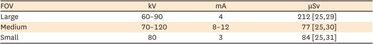
Suggested acquisition parameters grouped by field of view (FOV) size
| FOV | kV | mA | μSv |
|---|---|---|---|
| Large | 60–90 | 4 | 212 [2529] |
| Medium | 70–120 | 8–12 | 77 [2530] |
| Small | 80 | 3 | 84 [2531] |
It has been suggested that combinations lower than stipulated by the manufacturers (between 80–100 kV and 8 mA), allow a substantial reduction of the radiation dose while maintaining diagnostic accuracy and/or image quality [32]. Additionally, it has been reported that significant dose reductions can be made for relatively low-resolution tasks like pre-surgical implant planning by reducing tube current by up to 50% [33]. For endodontic therapy purposes, the use of a limited FOV with effective doses of 13 μSv for mandibular anterior teeth, 11.7 μSv for mandibular molars, 44 μSv for maxillary canines and premolars, 7.4 μSv for maxillary incisors and 6.3 μSv for maxillary molars have been reported [34]. Additionally, it is advised to adjust the X-ray source and detector’s degree of rotation from 360° to 180° in order to reduce the effective dose to the patient in half without compromising diagnostic accuracy [335].
Regarding the image acquisition settings, care should be taken when selecting the FOV and voxel size in a manner that is pertinent to the clinical situation being evaluated (Figure 6) [36]. Although small FOVs are generally recommended, conditions of traumatic origin, extensive periapical pathologies or treatment planning under the development of static or dynamic navigation protocols could be a decisive factor in the selection of larger FOV in favor of an adequate understanding of the operative field (Figure 7) [2021].
Figure 6
(A) View in the 3 orthogonal planes and 3-dimensional (3D) volume of an entire mandible (large field of view [FOV]). Note the amount of noise/artifacts generated in a large scan volume that outputs a low image resolution. (B) View in the 3 orthogonal planes and 3D volume of a segment in the maxilla (small FOV). Note the high resolution of the image generated in a more specific scanning.
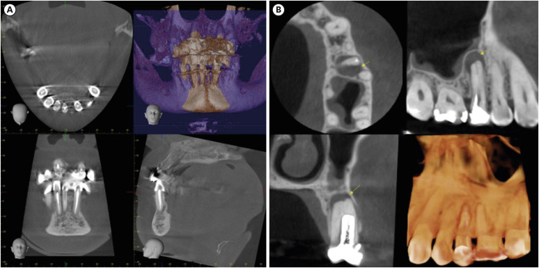
Figure 7
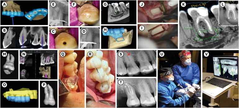
Treatment planning under the development of static/dynamic navigation protocols. (A-F) Guided endodontic for managing a canine with a coronal and cervical calcified canal. (A, B) 40 × 50 mm field of view (FOV) and 75 µm voxel cone-beam computed tomography (CBCT) scan with endodontic access guide design. (A) Virtual 3-dimensional (3D) template. (B) CBCT image of the canine with model scan aligned to the 3D template. (C-F) Guided endodontic treatment clinical sequence. (G-L) Guided endodontic microsurgery “Bone Window” technique. (G, H) 40 × 50 mm FOV and a 75 µm voxel CBCT scan with a 3D template design for osteotomy using the cortical window approach. (I, J) Rectangular osteotomy using piezoelectric saws. (K) Representative linear measurements of the periapical lesion obtained with the CBCT scan and the location of the inferior alveolar nerve. (L) Post-surgery (2D image). (M-T) Guided auto-transplantation of maxillary molar. (M, N) 40 × 50 mm FOV and a 75 µm voxel CBCT scan with tooth segmentation of the left maxillary third molar (tooth #28) from CBCT images. (O, P) 3D model of maxillary molar (tooth #28) and 3D template design to guarantee proper insertion into the receiving socket (left maxillary second molar [tooth #27]). (Q, R) Clinical auto-transplantation procedure with printed replica tooth (tooth #28) in a suitable position for placement of the natural donor tooth afterwards. (S, T) 2D radiographic follow-up. (U, V) Computer-aided dynamic navigation (Navident, ClaroNav, Ontario, Canada). Training on the dynamic navigation process using a biomodel.
Voxel size less than 200 μm (size of the periodontal ligament space) is recommended for the analysis of small or medium size periapical pathologies, which allows observing changes at the level of the peri-radicular tissues as primary signs of endodontic disease [23]. Small voxel sizes are also recommended for longitudinal measurement of anatomical structures, and when suspicion of vertical root fractures (VRF) [2937]. Images with smaller voxel values allow a better agreement between the measurements of the scan and the manual measurements [29]. High (200 μm) resolution and medium (300 μm) resolution CBCT images, for example, can be used to detect root resorption defects more effectively as opposed to low-resolution CBCT scans (400 μm) [38].
A limiting factor for the use of CBCT in endodontics occurs when restorative materials generate images of great hyper-density, which in turn increases the production of artifacts, making it difficult to observe the anatomical areas under study. Therefore, the modification of the operating conditions has been proposed using kV values at the lower limit of the established range, resulting in images adequate for the observation of the root canal system [39]. Likewise, it has been suggested that artifacts can be reduced when imaging endodontically treated root fractures, using a 360° as opposed to 180° rotation, thus improving specificity [22].
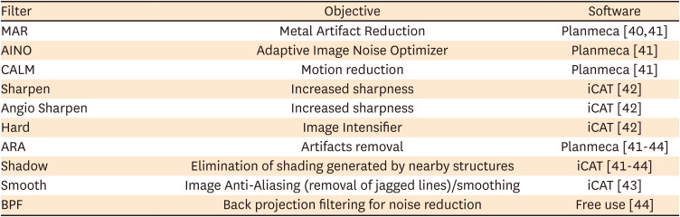
Another solution to this limitation caused by the presence of metal artifacts is the use of different methods of reconstruction after the acquisition of the data, implementing in the visualization software the option of modifying the algorithms, to eliminate the effects produced by the hardening of the beam, the linear artifacts and noise [4041424344]. However, the available literature on the use of these imaging reconstruction mechanisms for endodontics is limited and the results obtained under different methodological designs are contradictory (Table 3) [4041424344].
Table 3
Most popular filters in use for the observation of cone-beam computed tomography in endodontics
| Filter | Objective | Software |
|---|---|---|
| MAR | Metal Artifact Reduction | Planmeca [4041] |
| AINO | Adaptive Image Noise Optimizer | Planmeca [41] |
| CALM | Motion reduction | Planmeca [41] |
| Sharpen | Increased sharpness | iCAT [42] |
| Angio Sharpen | Increased sharpness | iCAT [42] |
| Hard | Image Intensifier | iCAT [42] |
| ARA | Artifacts removal | Planmeca [41424344] |
| Shadow | Elimination of shading generated by nearby structures | iCAT [41424344] |
| Smooth | Image Anti-Aliasing (removal of jagged lines)/smoothing | iCAT [43] |
| BPF | Back projection filtering for noise reduction | Free use [44] |
CBCT IMAGING INTERPRETATION IN ENDODONTICS
The proper interpretation of the CBCT is based on the exhaustive knowledge of the anatomy of the acquired volumetric image, the anatomical variations and the observation of anomalies [3345]. In this regard, all image information must be systematically reviewed, consequently, it is important to keep in mind that CBCT images comprise 2 components: (i) the generation of specific tasks of the image and (ii) the subsequent interpretation report. Frequently, a patient’s diagnosis can be complex, and its management may require an interdisciplinary group of specialists, for which an interpretation report serves as the optimal method for collating the tomographic findings [3345].
Specific image tasks
The reconstruction process creates a 3D matrix that can be visualized in a series of cross-sectional 2D images (axial, sagittal and coronal) [33]. Initially, CBCT data should be considered as a volume to be explored and from which other images can be extracted. This involves applying a protocol or logical sequence of phases to optimize the presentation of the image as follows [33].
1. Correct the data
The initial adjustment involves reorienting the data, which is simply realigning the patient’s anatomical profiles in the 3 orthogonal planes (axial, sagittal, and coronal), which can be visualized simultaneously, to make a 3D analysis of the area of interest [333]. The volumetric data set in an endodontic analysis must be adjusted so that the root canal is located, and subsequently, the longitudinal axis of the tooth matches the vertical axis in the CBCT screen image. The dataset can then be optimized by adjusting brightness, contrast, thickness and interval of cross-sectional slices and applying specific filters (e.g., interpolation, noise reduction). Subsequently, secondary algorithms for annotations, measurements, angulations and magnification can be used [33].
Tomographic slices can be as thin as a voxel thickness (80–400 µm) [3]. Slice thickness affects the image’s resolution, which in turn affects how accurately it is interpreted. The slice thickness is inversely proportional to image noise [46]. Common sense suggests that a thin, magnified slice provides greater documentation, however, there is insufficient scientific support for this assumption. Typically, a thicker slice improves the image’s contrast and can assist in identifying the volume of interest with greater precision [4647]. Several studies have tried to identify the ideal slice thickness for different analyses; however, the results are inconsistent [20464748495051]. Recently, Pham et al. [47] reported that there was a higher agreement between an electronic apex locator and CBCT at a slice thickness of 1.2 mm (p = 0.349) than at 0.6 mm (p < 0.001) in terms of root canal length estimation [47]. On the other hand, Moudi et al. [48] reported a high accuracy in the diagnosis of VRF using CBCT slices at a thickness of 0.3 mm. Notably, the accuracy did not decrease in the presence of gutta-percha [48]. However, other studies using thinker slices have reported that CBCT is not accurate in detecting VRF. Moreover, the imaging artifacts caused by gutta-percha result in an overestimation of the VRF [49].
2. View the data
Due to the large number of components of orthogonal images in each plane, it is necessary to review each series dynamically by scrolling through the orthogonal image. By selecting and moving the cursor over 1 of the 3 planes and in correct alignment with the longitudinal axis of the tooth/root of interest, the structure in the other 2 planes is simultaneously altered, thus allowing the area of interest to be traversed in real-time [333]. It is recommended that the displacement is done craniocaudally and then in the opposite direction, slowly in areas of interest or greater anatomical complexity. This traversal process must then be performed on the other 2 planes [33].
3. Display the data
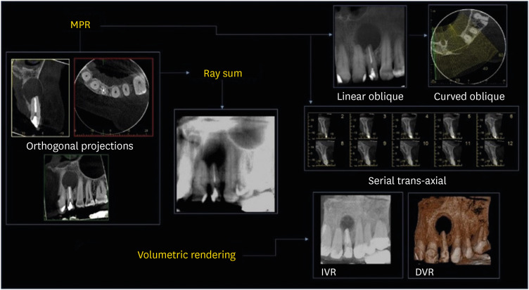
The CBCT software offers several display options, all focused on highlighting specific components of the volumetric data set. Due to the nature of the isotropic acquisition, the volumetric data set can be sectioned non-orthogonally to provide non-axial 2D flat images referred to as Multiplanar Reformatting (MPR) (Figure 8). MPR mode includes the following transformations: linear oblique and oblique curve, which project simulated panoramic images free of distortion, and serial trans-axial reformatting [33]. All of them are very useful in highlighting specific anatomical regions and facilitating the diagnostic task. Due to the numerous components in the orthogonal images of each plane, and the difficulty in relating adjacent structures, 2 additional methods have been designed to visualize adjacent voxels: (i) Ray sum or ray casting and (ii) Volumetric rendering (Figure 8) [3350].
Figure 8
Cone-beam computed tomography (CBCT) volumetric data display mode options. Multiplanar Reformatting (MPR) includes linear oblique, curved oblique, and serial trans-axial imaging. Ray sum is comprised of increased thickness section images. Volumetric rendering consists of indirect volumetric rendering (IVR) and direct volumetric rendering (DVR). Adapted from Scarfe et al. [33].
1) Ray sum or Ray casting
An MPR image can be increased in thickness by increasing the number of adjacent voxels. This creates an “image slab” that displays a specific patient volume, referred to as a ray sum. Total thicknesses of ray sum images can be used to generate simulated projections such as lateral cephalometric images. Unlike conventional X-rays, ray sum images are not magnified and undistorted. However, this technique uses the complete volumetric data set and the interpretation suffers from anatomical noise and overlapping of multiple anatomical structures [3350].
2) Volume rendering
It refers to techniques that allow the visualization of volumetric data by integrating large volumes of adjacent voxels and a selective display. For this purpose, 2 techniques have been described: indirect volume rendering (IVR) (Figure 8) and direct volume rendering (DVR) [3350]. IVR includes the selection and graphical representation of a range of grayscale intensity levels for voxels called segmentation, where a volumetric surface reconstruction with depth is obtained. DVR involves selecting an arbitrary limit of voxel intensities, and removing all grayscale values below or above [3350]. The most common DVR technique is Maximum Intensity Projection, and its visualizations are achieved by evaluating the values of each voxel along an imaginary projection beam from the eyes of the observer and for a particular volume of interest, where the high values will be displayed as display values [3350]. Rendering, in general, enables the creation of real 3D images that can be segmented and then printed for the performance of clinical and laboratory procedures.
CBCT interpretation report
There is no consensus on specific requirements for endodontic CBCT reports. However, comparative guidelines for the multi-slice computed tomography report have been widely recommended [3345].
1. Patient information
This section should include information such as names and surnames of the patient, identification, residence address, contact telephone number, email, date of birth, age, sex and even ethnicity. These last 3 aspects are important for establishing varying diagnoses, for example, bone cement dysplasia may be more frequent in women over 40 years of age and African/Afro-Caribbean ethnicity [334551].
2. Clinical aspects
This section has 2 objectives: first, to include information of relevance to the time the treatment is carried out, and second, to contextualize the information for those cases that need a second evaluator. Systemic conditions of relevance such as bisphosphonate treatments, signs and symptoms of pain in teeth with or without endodontic treatment, history of dental trauma and atypical facial pain should be recorded. This section should finally highlight whether other previous imaging tests were taken and should justify the need for CBCT [4552].
3. Scan information (radiography log)
This section will include the date, name and location of the place where the CBCT was taken and the name of the referee. Additionally, the type of equipment used, the exposure parameters of the scan (180/360 rotation, kV, mA, exposure time and resolution) and relevant information such as problems during the procedure (e.g., patient movement) should be included in this section. All this information will be relevant when diagnosing a low-quality CBCT. In cases that require follow-up, these parameters may be modified or replicated according to the quality of the CBCT image previously obtained [4552].
4. Radiological findings
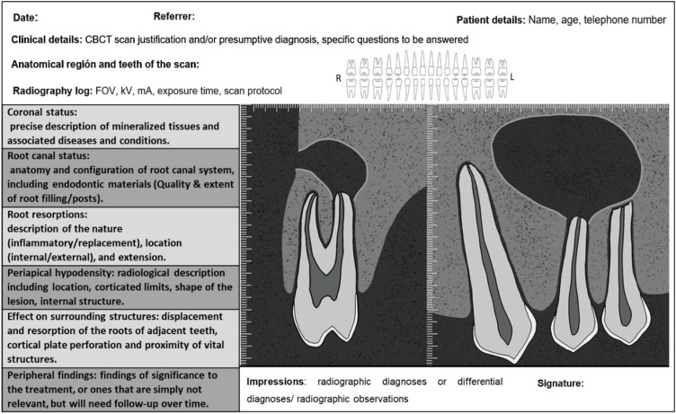
A complete exploratory view of the entire volume of CBCT data, systematically executed in the 3 orthogonal planes is considered an adequate practice according to the European Society of Endodontics in 2019 [4552]. Concentrating only on the area of interest (e.g., a tooth with a suspected endodontic problem) is an inappropriate practice, which may lead to omitting incidental findings that may be considered negligence on the part of the clinician [52]. Figure 9 diagrammatically illustrates the information that should be included in an endodontic CBCT scan report.
Figure 9
Suggested cone-beam computed tomography (CBCT) endodontic report adapted from Patel et al. [45].
FOV, field of view.
ARTIFACTS
Unfavorable artifacts or alterations of CBCT images are defined as image alterations induced by discrepancies between mathematical modeling and the actual physical imaging process; due to the technical composition/setup of the scanner, the composition, position and behavior of the object under investigation and finally the simplified mathematical assumptions used for 3D reconstruction [1453]. Since artifacts can interfere with the diagnostic process performed on CBCT datasets, practitioners must be aware of their possible presence and estimate them during imaging analysis. In endodontic CBCT, the following mainly stand out: (i) noise, defined as the result of inconsistent attenuation values in projection images, derived from rounding and photon counting errors; scattering, caused by photons diffracting from their original path after interaction with matter, resulting in an increase in measured intensities. (ii) X-ray beam artifacts that arise from the polychromatic nature of their projection, leading to Beam hardening (increase in average energy as a result of low-energy photons being absorbed instead of high-energy photons), which in turn results in 2 types of artifacts: distortion of the metal structure caused by the difference in absorption or cupping artifact and dark streaks or bands that may appear between 2 dense objects. As a result, the presence of restorations, including apical obturation materials, may result in severe stains in the resulting images. In endodontics, using CBCT with a small or reduced FOV helps produce clearer images by preventing the scanning of structures outside the area of interest, which reduces the resulting Beam hardening [5053]. and finally, (iii) Motion Artifacts, in which a misalignment occurs either of the sources, the object or the detector effect that causes inconsistencies in the process of rear projection. Therefore, the lines along which the rear projection takes place do not correspond to the lines along which the attenuation was recorded (Figure 10) [54].
Figure 10
Most common cone-beam computed tomography-related artifacts in endodontics. (A) Noise. (B) Beam hardening. (C) Movement.
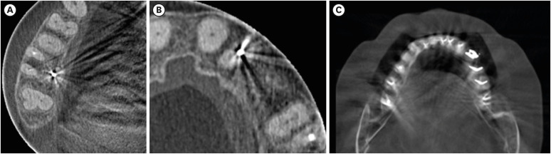
Understanding the underlying cause of, identifying, and diagnosing imaging deficiencies and artifacts is crucial, hence avoiding their appearance in later shots. The existence of artifacts resulting from the presence of high-density materials, such as gutta-percha and sealers, dental solid or metal structures, and/or other hyperdense materials, which may impair contrast and image quality, is one of the main challenges in endodontic diagnosis with CBCT [5556]. Any systematic discrepancy between the reconstructed image’s grayscale values and the object’s actual attenuation coefficients can be defined as an artifact [5556]. Endodontic artifacts can take the form of a variety of patterns, including streaks, hypodense halos, and shadows that are aligned with the projection lines. Intracanal filling materials may also result in volumetric distortion or blooming, which causes the obturations to appear larger than they actually are on CBCT. Similarly, artifacts that mask actual root canal structures may appear on CBCT scans of teeth that include intracanal hyperdense materials, increasing the chance of clinical diagnostic mistakes. Misinterpretations of CBCT scans have the potential to seriously complicate diagnosis, result in mistakes in clinical judgment and decision-making, and jeopardize tooth survival [5556]. As a result, every professional involved in interpreting CBCT images for endodontic purposes must have a thorough understanding of the nature of these artifacts, the application of particular CBCT acquisition parameters for endodontic images, and the knowledge of software with a reduction algorithm that can attenuate these artifacts.
DIGITAL IMAGING AND COMMUNICATION IN MEDICINE (DICOM) FILES
DICOM specifies a format for storing and exchanging biomedical digital imaging data [57]. Currently, DICOM is considered the standard format protocol for CBCT-based data sets. Several visualization software can input DICOM files and export sections or images in different formats, which can then be utilized for precise analysis [5457]. In contrast to other image formats, DICOM organizes data into sets. A header and image data sets are combined into a single file to form a DICOM file. The header contains the patient’s biographical data, imaging study acquisition settings, picture dimensions, matrix size, color space, and a variety of other non-intensity data necessary by the computer to display the image properly. The image data set (stored as a series of 0 second and 1 second) includes all of the image's pixel intensity information, which can be used to reconstruct the image by using the information from the header [58]. DICOM not only defines the image and data sets. The complete standard is divided into up to 18 interconnected but separate sections, including the definition of information objects, service class specification, encoding, data dictionary, message exchange, network support for message exchange, communication using physical media, greyscale visualization, security, content mapping resource, explanatory information and the Web access to DICOM persistent objects among others [59]. DICOM offers several advantages, such as the ability to communicate patient information and images via a single network session, improved patient safety (keeping data and images together), consistent standards across multiple devices and storage of rich acquisition and imaging protocol data [54].
CONCLUSION
CBCT allows us to navigate the 3D structures in the traditional and alternative volumetric planes, which leads to increased sensitivity for the accurate detection of endodontic pathologies/conditions. CBCT as a diagnostic, planning and follow-up tool should be restricted to endodontic cases of medium to high complexity. The main concerns regarding CBCT are the radiation dose that patients are exposed to during the scanning and the appearance of noise/artifacts in tomographic images that result from photon diffraction or absorption by anatomical structures or dental materials. Likewise, errors made when interpreting tomographic images may result in clinical procedure failures and complications. Appropriate fields of view, small voxel size, low mA levels, and brief exposure times are recommended as the best acquisition parameters in endodontics. Furthermore, implementing the option of modifying the algorithms to eliminate the effects produced by the hardening of the beam, the linear artifacts and the noise may make precise volumetric image analysis easier. Likewise, 3D volume interpretation must be approached systematically and reproducibly to improve precision in terms of diagnosis and planning of endodontic clinical procedures.
 XML Download