

 PDF
PDF Citation
 Print
Print


INTRODUCTION
With the increasing adult demand for more esthetic orthodontic appliances,1 many orthodontists have started to make their own in-house clear aligners with the aid of computer-aided design/computer-aided manufacturing (CAD/CAM)-technology.2 Orthodontists use different commercially available thermoplastic materials to manufacture the clear aligners on dental models that express the desired tooth movement. Recent technological advancements have made it possible for clinicians to bypass impressions, printing of the models, and print the aligners directly.
The traditional manufacturing process for clear aligners can be divided into four steps: acquisition of the original dental anatomy, manipulation of teeth, three-dimensional (3D)-printing, and thermoforming. Novel techniques allow practitioners to print aligners directly, thereby eliminating the thermoforming step in aligner manufacturing.3,4 These new techniques employ a photopolymerizable resin with a digital light processing (DLP) printer to print material of appropriate thickness and elasticity for aligner use. The application of this technology in current orthodontic practice offers the potential for increasing efficiency and reducing waste. Furthermore, inaccuracies associated with 3D printing of models5 and the thermoforming process can be eliminated in direct-printed aligners. However, before direct-printed aligners are adopted, they need to be compared to traditional thermoformed aligners. To date, the dimensional accuracy of direct-printed aligners has not been tested against those of traditional thermoformed aligners.
Previous studies on the accuracy of aligner fit have reported average discrepancies far beyond the ranges of clinical acceptability. Mantovani et al.6 measured the aligner gaps of two commercially available aligner systems by using scanning electron microscopy and found average discrepancies ranging from 0.102 mm to 0.351 mm. Lombardo et al.7 measured aligner gaps of five commercially available aligner systems using micro-computed tomography (micro-CT) scans and found discrepancies ranging from 0.047 mm to 0.651 mm. If the discrepancy between the aligner and the tooth is greater than 0.25 mm at a site where 0.25 mm movement is prescribed, no clinically appreciable tooth movement will occur. This discrepancy of fit could be a potential cause for the lack of movement accuracy of up to 57% in some planned orthodontic movement.8 Furthermore, failure of teeth to follow their planned tooth movement is one of the most common complications in clear aligner therapy.9
Dimensional accuracy is a common research topic in dentistry since many dental prostheses have to fit very accurately in order to improve longevity and reduce the risk of pathology in the oral cavity.10 Several methods are available to assess dimensional accuracy. Three methods that have been employed to assess dimensional accuracy of thermoplastic dental materials for retainer use include the use of computer coordinate machines,11 optical scanners,12 and micro-CT.7 After the volume of a model and the volume enclosed by its respective retainer are measured, they are placed in a computer program that aligns the volumetric renderings with a best-fit function and digitally measures the distances at pre-selected reference points between the retainers.
Moreover, little is known about the dimensional accuracy of aligners or retainers. Cole et al.12 compared the dimensional accuracy of thermoformed retainers versus direct-printed retainers and found that direct-printed retainers had greater discrepancies. They used optical scanning and metrology software to assess accuracy at specific landmarks and found average discrepancies ranging from 0.1 mm to 0.3 mm for thermoformed retainers and 0.1 mm to 0.4 mm for direct-printed retainers. In contrast, Jindal et al.3 evaluated the geometrical accuracy of direct-printed aligners and found that crown heights were more accurate than those of their thermoformed counterparts. While the average discrepancy in thermoformed aligners was 0.37 mm, the corresponding value for direct-printed aligners was 0.21 mm. Prior to this study, the dimensional accuracy of direct-printed aligners had not been thoroughly evaluated.
All previous studies on direct-printed clear appliances used photopolymerizable polymethyl methacrylate with the brand name Dental LT Clear Resin® (Formlabs, Somerville, MA, USA),3,4,12 which has specific indications to print occlusal splints. However, a photopolymerizable polyurethane (Tera Harz TC-85DAP 3D Printer UV Resin®; Graphy Inc., Seoul, Korea) specifically indicated to print aligners has become available. Nevertheless, the dimensional accuracy of aligners printed with this novel photopolymerizable polyurethane has not been tested. This study used optical scanning and metrology software to compare the dimensional accuracy of specific anatomical landmarks between polyurethane direct-printed aligners and thermoformed aligners.
MATERIALS AND METHODS
Sample preparation
A standard tessellation language (STL) file of a maxillary arch with a 3-mm tooth-size-arch-length discrepancy was imported to MeshMixer (Autodesk, San Rafael, CA, USA), where it was trimmed into a horseshoe shape and based. Next, 24 models were printed horizontally with the SprintRay Pro (SprintRay, Los Angeles, CA, USA) DLP technology printer. SprintRay Die and Model Gray photoinitiated methacrylate resin with a flexural modulus of 1.8 GPa and flexural strength of 70.1 MPa (SprintRay) was used to print the models at a 50-µm-layer thickness.
The excess uncured resin was removed using two successive five-minute baths of 99.5% isopropyl alcohol and post-cured with a Procure® (SprintRay) curing unit according to the manufacturer’s recommendations. Next, 0.75 mm polyurethane thermoforming sheets (n = 12) of the brand Zendura FLXTM (Zendura Dental, Fremont, CA, USA) and 0.75 mm polyethylene terephthalate copolyester thermoforming sheets (n = 12) of the brand Essix ACETM (Dentsply Sirona, Sarasota, FL, USA) were used to pressure-form passive aligners with a Biostar® (Scheu-Dental GmbH, Iserlohn, Germany) thermoforming machine, in accordance with the manufacturer’s recommendations.
The aligners were then removed from their respective models and trimmed approximately 1 mm past the gingival margins. Once trimmed, their internal surface was sprayed with a CAD/CAM spray (Yeti Dental, GmbH, Engen, Germany). A Trios 3 intraoral scanner (IOS, 3Shape, Copenhagen, Denmark) was used to scan the intaglio of the thermoformed aligners. Trios 3Shape software (3Shape) post-processed the scans and converted them into STL format.
Next, using the maxillary master STL file, 12 passive direct-printed aligners were digitally designed using MeshMixer to a thickness of 0.5 mm and to cover 1 mm above the gingival margin. Then, they were printed with a SprintRay Pro using strut supports at a 50 µm-layer-thickness by using the Tera Harz TC-85DAP 3D Printer UV Resin. Subsequently, they were post-cured with a Cure-M (Graphy Inc., Seoul, Korea) curing unit according to the manufacturer’s recommendations. Finally, the supports were removed, and the aligners’ intaglio was sprayed with CAD/CAM spray. An E3 laboratory scanner (3Shape) was used to scan the direct-printed aligners.
Measurement method
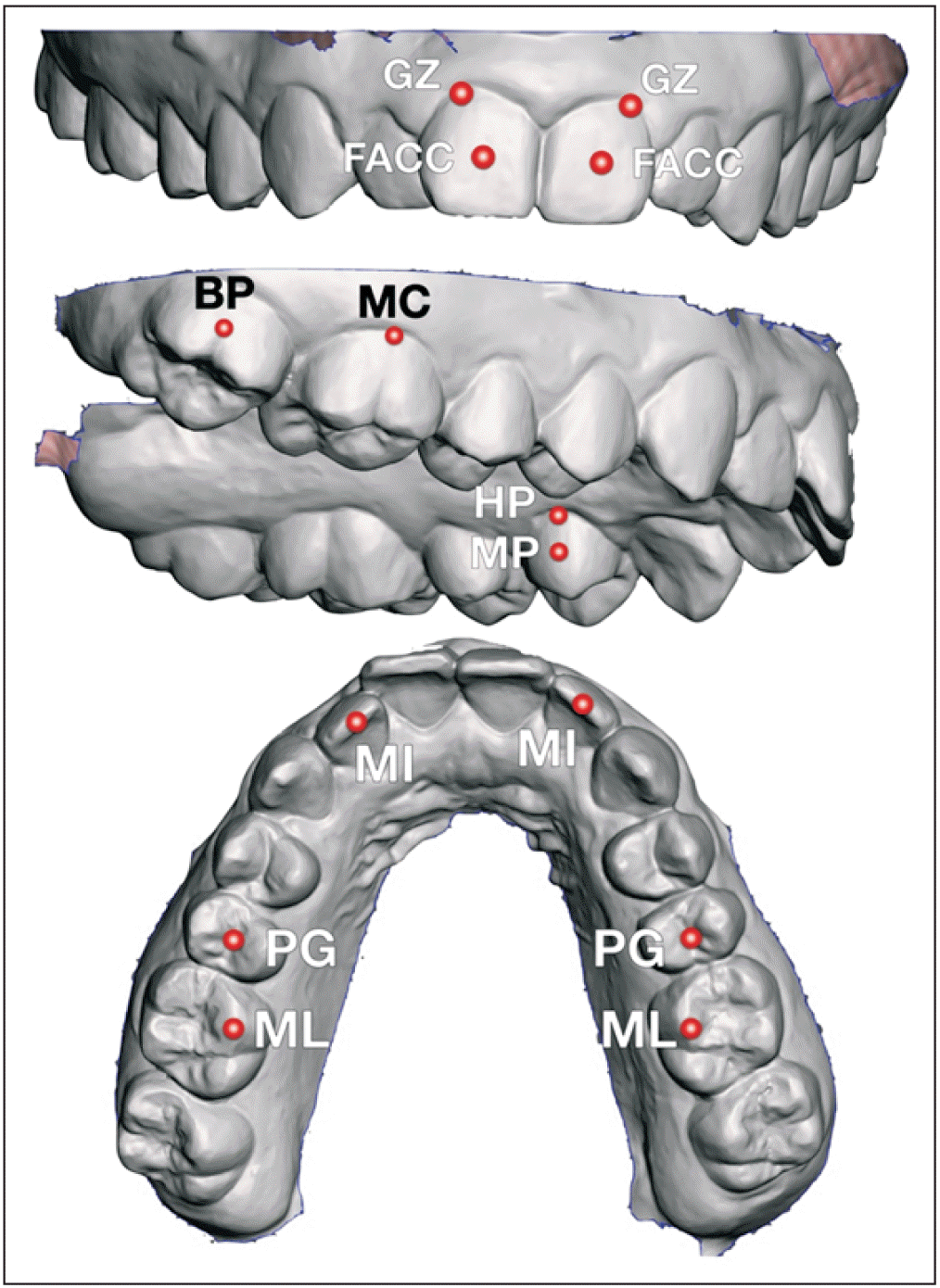
The STL file of the maxillary dental arch was imported into Geomagic® Control XTM metrology software (3D Systems, Morrisville, NC, USA) and selected as the reference model. Then, the STL files of the aligners’ intaglio were individually imported and superimposed on the STL files of the maxillary dental arch by using the best-fit alignment algorithm, which superimposes both meshes with the shortest distance between every data point. Linear distances between meshes in the files of the aligner’s intaglio and the STL files of the maxillary dental arch were measured at three bilateral landmarks located at the incisal/occlusal portions of teeth, namely, the mid-incisal edge point of the lateral incisors (MI), midpoint on the central groove of the second premolars (PG), and the mesio-lingual cusp tips of the first molars (ML); three bilateral landmarks located at the mid-crown level, namely, the functional axis of clinical crown points of central incisors (FACC), the midpoint on the palatal surfaces of the first premolars, and the buccal pits of the second molars (BP); and three bilateral landmarks located at the gingival margins: the zenith point of the central incisors (GZ), the highest point on the palate-gingival margin of the first premolars (HP), and the central point on the gingival margin of first molars (MC) (Figure 1).
Sample size calculation
Based on the study by Cole et al.12 a standard deviation of 0.15 mm was determined. The clinically significant difference in mean error was estimated to be 0.25 mm, and this value was consistent with the literature.13 At each of the 18 different landmarks, pairwise t-tests were planned among the three types of aligners. Using a non-adjusted error rate of α = 0.05, the power was estimated to be 0.974 when the sample size was 12, so a sample size of 12 aligners per type was specified.
Statistical methodology
The millimetric distance between the point in the aligners intaglio mesh and the same point in the STL model of the maxillary dental arch was measured and compared between the types of aligners (trueness) and within the same types of aligners (precision). For this comparison, the left and right absolute mean discrepancies at every landmark were averaged for every sample. Root mean square (RMS) value was used to assess overall trueness.
This measurement is not affected by negative or positive values and is commonly used in the literature as a measure of trueness.13-15 It takes into account the differences between the reference and measured values at every point in a model. Furthermore, it is considered an absolute error index that indicates the magnitude of error and has symmetry, allowing interchangeability of data.
Statistical calculations were performed using IBM SPSS software (version 25.0; IBM Corp., Armonk, NY, USA). For the assessment of method reliability, measurements were obtained for all the landmarks and the RMS values for the best-fit alignment superimpositions were obtained from 72 randomly selected measurements by a single examiner (N.K.). All data were measured twice at an interval of 2 weeks by the same operator. Intra-observer random error was estimated using intra-class correlation coefficient (ICC) and method errors [√(Σd2/2n)], and systematic differences were assessed using a paired t-test. Normality of the distribution of variables was rejected by the Shapiro–Wilk test. Permutation t-tests were used to compare the means among aligner types at specific landmarks and overall (RMS). Bootstrapping was used for the construction of the 95% confidence intervals.
RESULTS
Intra-observer systematic errors were very similar. Of the 10 differences, none showed a statistically significant difference between the first and the second replicates. Method errors ranged from 0.000 mm (FACC) to 0.07 mm (MI). ICC values ranged from 0.802 to 1.000 and were consistently high with excellent reproducibility.
The lowest mean absolute discrepancy between the master STL mesh and aligner at a specific anatomical landmark was 0.072 ± 0.035 mm (Direct-printed aligner-PG landmark), and the highest mean absolute discrepancy was 0.457 ± 0.350 mm (Essix ACETM aligner-BP landmark). The second lowest absolute mean discrepancy of 0.076 mm was observed for the Zendura FLXTM aligners located at GZ of the central incisors. In the thermoformed aligner group, the larger absolute mean discrepancies were usually associated with larger standard deviations, but this did not hold true for the direct-printed aligners. Standard deviations in the thermoformed aligner group ranged between 0.057 mm (Zendura FLXTM aligner-GZ landmark) and 0.422 mm (Essix ACETM-MC landmark) while standard deviations in the direct-print aligner group ranged from 0.033 mm to 0.055 mm. Standard deviations for absolute mean discrepancies were greater for Essix ACETM aligners at every landmark.
The discrepancies between the STL master model meshes and the aligner meshes were measured by determining RMS values.14,15 Values closer to zero represent greater exactness between both models, with a value of zero denoting perfect fit. The highest RMS value was observed in the Essix ACETM aligner group while the lowest value was observed in the direct-printed aligner group (Table 1).
Tests for the equality of means between the aligner types showed significant findings at several landmarks. Specifically, absolute mean discrepancies were significantly different between the three aligner types at ML. Both thermoformed aligners differed significantly from the direct-printed aligners at PG. The Essix ACETM and direct-printed aligners differed significantly at three other landmarks, MI, MC, and BP. Moreover, the Zendura FLXTM and direct-printed aligners differed significantly at HP. At all other landmarks, no significant differences were found (Table 2).
DISCUSSION
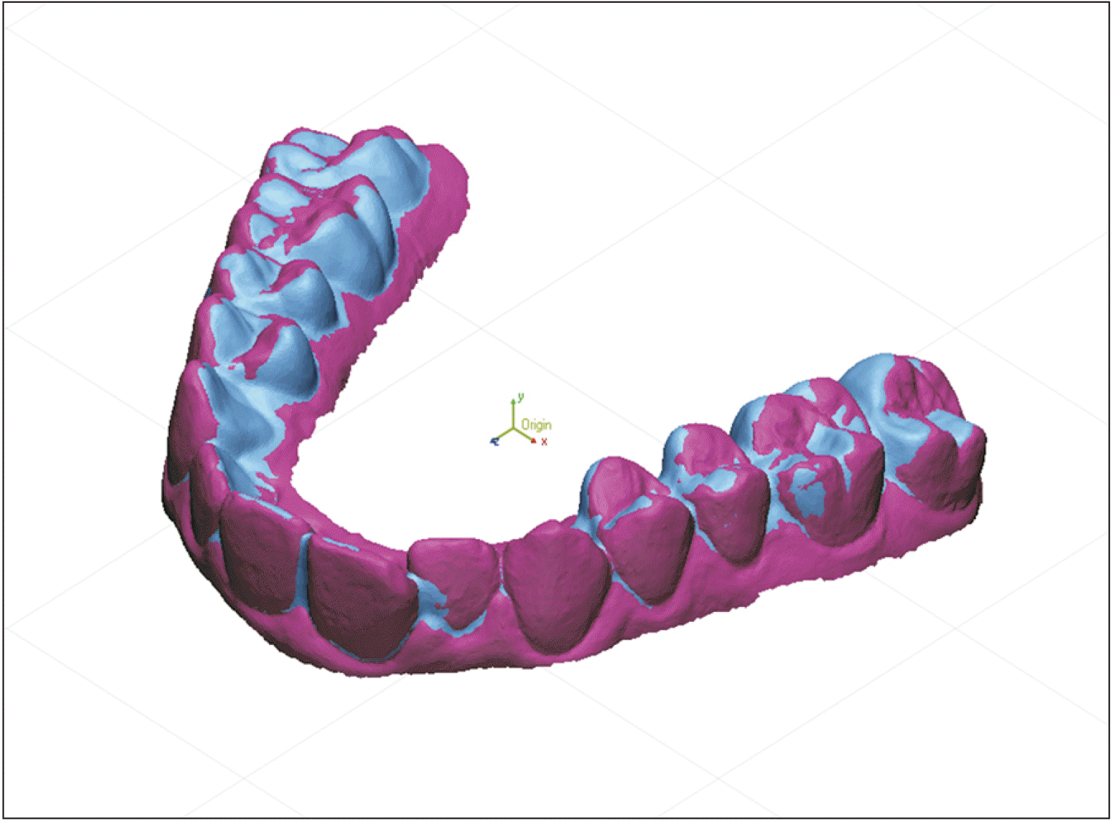
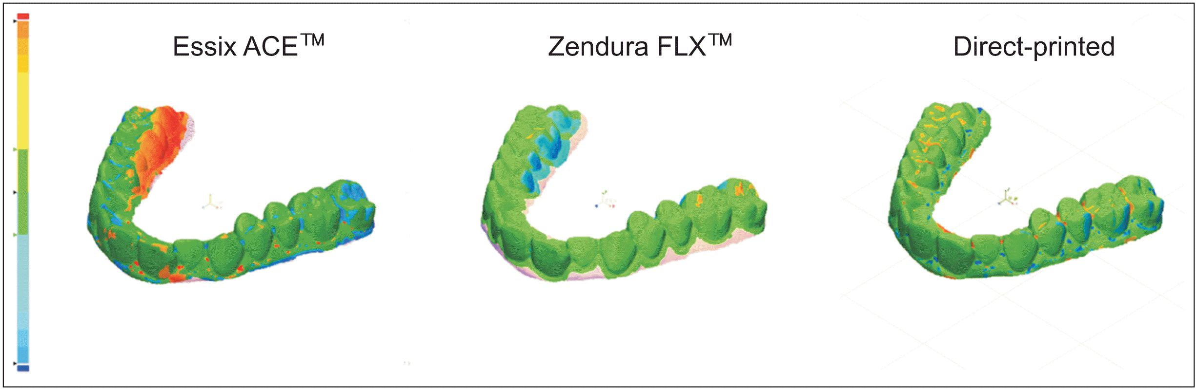
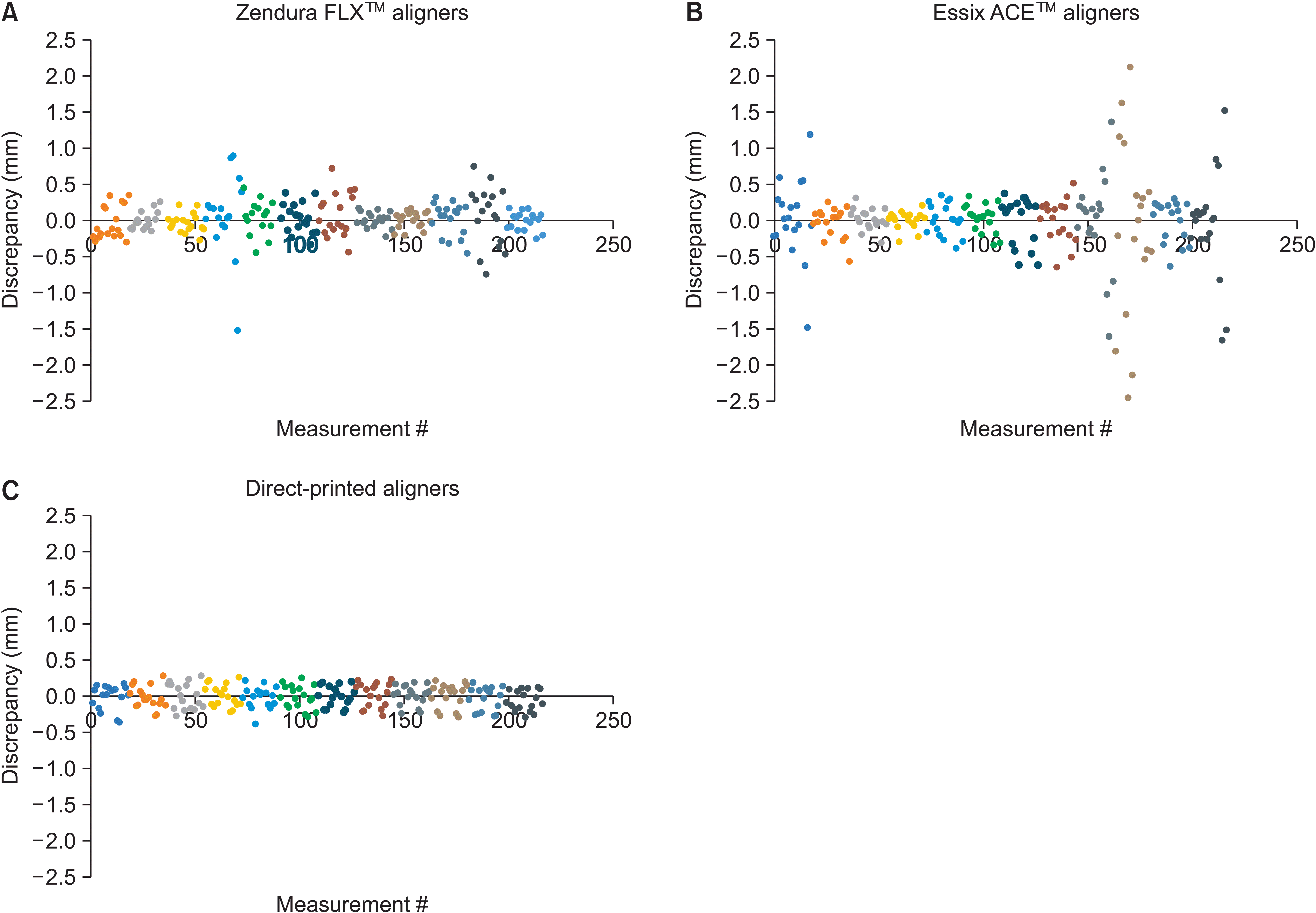
The evidence provided by this sample suggests that direct-printed aligners fit more accurately than their thermoformed counterparts. Significant differences were found between direct-printed aligners and thermoformed aligners at six of the nine investigated bilateral landmarks (Tables 1 and 2). Moreover, discrepancies between the master STL mesh and the aligner meshes were positive at some landmarks and negative at others (Figure 2), and aligner intaglio scans deviated more in thermoformed aligners than in direct-printed aligners (Figures 3 and 4), indicating that the direct-printed aligners had greater trueness. The distribution of landmark measurements was more varied in the thermoformed aligners (Figure 4), as evidenced by their greater standard deviations (Table 1), which indicated that the direct-printed aligners also had greater precision.
Similar to the present study, Cole et al.12 compared the fit of two types of thermoformed retainers and one direct-printed retainer. One of the thermoformed retainers was made in-house with 1-mm-thick Essix A+ (polyethylene terephthalate copolyester) while the other was a laboratory-made Vivera retainer (Align TeWWchnology Inc., San Jose, CA, USA). For the direct-printed retainers, the master casts were scanned and three retainers per master cast were printed at 0.75-mm thickness with Dental LT Clear Resin® (Formlabs, Somerville, MA, USA) and a 100-µm print layer setting. Digital scans of the retainers were superimposed on their respective master model scans by using a best-fit algorithm with Netfabb (Autodesk, San Rafael, CA, USA) engineering software. With the engineering software, distances between the master casts and their respective retainers were calculated at the same landmarks as those used in another study.10 In contrast to the present study, the thermoformed retainers showed the highest dimensional accuracy, with mean absolute values ranging from 0.1 mm to 0.3 mm, while the direct-printed retainers showed mean absolute values ranging from 0.1 mm to 0.4 mm.
In this study, the reduced dimensional accuracy of thermoformed aligners may be associated with several steps in their manufacturing process. First, the greater number of steps involved in the manufacture of thermoformed aligners than that of direct-printed aligners itself increased the scope for errors. Loss of fidelity may occur at any of these steps and propagate throughout the manufacturing process. For example, thermoformed aligners are only as accurate as the models they are formed on, and 3D printing is associated with errors.13 The thermoforming process can also be subject to error, since underheating has been found to hinder the aligner’s dimensional accuracy.16
The direct-printed aligners used in this study were printed with SprintRay Pro using Tera Harz TC-85DAP 3D Printer UV Resin. SprintRay Pro is a DLP printer that is more rapid than the laser exposure formats, and is highly accurate with a high-resolution structure and distinct edges.17 According to a comparative analysis of orthodontic aligners produced by different 3D printers,18 the mechanical properties of direct-printed aligners were dependent on the type of 3D printers used for producing the aligners. SprintRay Pro showed the least Martens hardness, indentation modulus, and elastic index, which means the appliance would be more susceptible to wear but less brittle. In addition, the printed aligners produced by DLP printers had lower mechanical properties than those produced by liquid crystal display printers. Although the effect of the mechanical properties on the clinical efficacy has not been investigated, different 3D printers might produce the output with different levels of precision.19 To compare the dimensional accuracy among the aligners with various 3D printers, additional evaluations should be performed in future studies.
This study had several limitations. First, the scanning spray added a significant error to the dimensions of the aligner’s intaglio. The translucent nature of clear aligners presents a challenge for capturing their inner surface with an optical scanner.4 To facilitate scanning, a contrasting spray was applied on the aligner’s intaglio adding a layer of material. The literature has reported the thickness of contrasting spray to range between 0.01899 mm and 0.0803 mm. The exact contribution of the spray to the aligner thickness was not quantified in the study, but it is certain that it affected the measurements.
A further limitation in this study was that two different scanners were used to scan the samples. More specifically, an E3 laboratory scanner was used to scan the direct-printed aligner samples, while a Trios 3 IOS was used to scan the thermoformed aligner samples. While the respective manufacturing companies claim that the E3 laboratory scanner has an accuracy of 0.007 mm and the Trios 3 has an accuracy of 0.0069 mm, significant differences have been found when the same dental models were scanned by a laboratory scanner and an IOS of the same brand.20
Another potential source of error could be the method used for superimposition of the compared meshes. While a best-fit alignment method is commonly used to assess accuracy in dentistry,20,21 its validity can be questioned. Best-fit alignment is associated with a mean translation error of 0.130 mm when assessing occlusal tooth wear. The best-fit alignment in this method is only 0.009 mm more precise than a landmark-based alignment, which was used by Cole et al.12 A reference-based alignment method has shown to produce only a 0.022 mm mean translation error. Additionally, the increased accuracy of restorations determined by best-fit alignment methods does not correlate with clinical success of indirect restorations.
The different thicknesses used for the thermoforming material (0.75 mm) and the direct-printed aligners (0.50 mm) might be viewed as another limitation to this study, but the thicknesses were chosen deliberately for two major reasons. First, the thermoforming process reduces the thickness of the sheet, creating aligners from 0.125 mm up to 0.30 mm thinner than the original thermoforming sheet thickness. The reduction of thickness is not uniform and varies at different locations.8 Second, in the study by Edelmann et al.,4 direct-printed aligner thickness printed an average of 0.2 mm thicker than the actual thickness they were set to print at. Therefore, a common commercially available material thickness thermoforming material of 0.75 mm was decided upon by the investigators in this study.
It is challenging to correlate the results of in vitro investigations on the aligners with their clinical performance. Aligners are not completely rigid structures and, consequently, their dimensions change when they are placed over undercuts of teeth. Thus, measurement of the gaps between aligners inserted on their physical models, as was done by Mantovani et al.7 and Lombardo et al.,8 might offer a more valid representation of aligner fit in vivo. Nevertheless, to validly portray the fit of aligners in vivo, the anisotropic nature of the periodontal ligament has to be accounted for, a phenomenon that is impossible to recreate in the laboratory.
Several attempts have been made to recreate oral conditions in laboratory aligner research.22 Particularly, laboratory aligner research has confirmed that the aligner material degrades over time under simulated oral conditions. The hygroscopic expansion observed in polymers has been shown to affect the dimensions of aligners placed in water for two weeks.22 Although a more serious consequence of aligner degradation in the mouth could be the leakage of cytotoxic monomers in aligner polymers, this has never been documented in vitro.23,24
The low precision of thermoformed aligners found in this study could be due to inaccuracies in their manufacturing process. This is consistent with a study that compared the force systems delivered by a series of aligners manufactured from the same reference model using the same thermoplastic material but found that the aligners delivered different magnitudes of forces. Although the smallest layer thickness (50 µm) was used to print the dental models for higher accuracy, perfect consistency among the 24 models was not guaranteed due to the possible discrepancies. A larger sample size than that used in this study, 12 aligners per type, would help offset the precision issue. The difference in forces could also be attributed to inaccuracies in the manufacturing process. Direct-printed aligner technology is promising since it can overcome these inaccuracies associated with the manufacture of clear aligners, as was demonstrated in this study.
Ultimately, forces and moments move teeth,25 and a plastic appliance is merely a medium to apply these forces. Force systems delivered to one tooth in an aligner are influenced by the shape and position of adjacent teeth.26 It is very complex, albeit impossible to extrapolate the force system that an aligner will deliver in the mouth from an in vitro model. In conclusion, controlled clinical trials should be conducted with clear aligner therapy in order to evaluate aligner performance.27
The results of this study warrant future clinical research on direct-printed aligner technology. However, many factors, such as material properties, biocompatibility, and force systems delivered by direct-printed aligners need to be examined before making any clinical recommendations. For adoption of this new technology, direct-printed aligners need to perform as well or better than their thermoformed counterparts in the clinical arena. Aligner materials degrade over time28; their optical properties reduce29; and they absorb water in the oral environment,22,30 and these factors cannot be reproduced accurately in the laboratory. A randomized controlled trial is essential to draw decisive conclusions regarding the effectiveness of direct-printed aligners over thermoformed aligners.
CONCLUSIONS
The sample in this study demonstrated that direct-printed aligners were more precise and truer than the thermoformed aligners investigated in this study. This study might have been underpowered since the sample size calculation was invalidated, and scanning inaccuracies and sample preparation may have added errors to the measurements. Finally, the present study was performed in vitro; therefore, the results should be interpreted with care and not used to make any clinical decisions.
SUPPLEMENTAL VIDEO
A video presentation of this article is available at https://youtu.be/y4NddSXb79w or www.e-kjo.org.
 XML Download