

 PDF
PDF Citation
 Print
Print


INTRODUCTION
The global increase in aging population has also increased the incidence of neurodegenerative diseases.1 Major neurodegenerative diseases, such as Alzheimer’s disease (AD) and Parkinson’s disease (PD), are diagnosed by detection of abnormal protein aggregates such as beta amyloid (Aβ) and phosphorylated tau (p-tau) for AD, and alpha-synuclein (α-syn) for PD.2 To target these proteins, clinical trials that involve the assessment of investigational drugs (chemical or protein) or cell therapies have been conducted.34
One of the major challenges in delivering therapeutics to the brain is the blood-brain barrier (BBB). The BBB protects the brain from harmful toxins but also functions as a barricade in the crossing of molecules, proteins, and cells into the brain parenchyma. To date, drug delivery research has focused on changing the physico-chemical attributes of the therapeutics or implementing additional methods (e.g., application of ultrasound to the cerebrovascular system) to increase the permeability of the BBB.5678 However, changes applied to biopharmaceuticals (protein drugs, cell therapy, gene therapy) can alter the therapeutic activities of these products which will subsequently complicate the interpretation of efficacy and toxicity tests.910 Moreover, because therapeutic efficacy may vary depending on the surrounding microenvironment of the administered site, accurate administration to the lesion site is of utmost importance.
Mesenchymal stem cells (MSCs) have recently gained considerable interest as a potential therapeutic option for neurodegenerative diseases.111213 In previous studies, we found that MSCs administered via blood vessels (intravenous,14 intra-arterial15) were not detected in the brain, presumably due to the BBB. Unlike administration via the bloodstream, direct injection causes injury to the brain.16 The intracranial approach, however, holds great therapeutic potential due to the accuracy in delivering drugs.17 Intracranial administration includes delivery via the intracerebroventricular (ICV) or parenchymal route. While precise and accurate delivery to the lesion site may be difficult, the administered drug may be distributed widely throughout the brain when delivered via the ICV route. The washout of the therapeutics via cerebrospinal fluid (CSF) flow may reduce the overall therapeutic effects.18 On the contrary, while parenchymal injections can only target a limited region of the brain, delivery to the lesion site can be accurately performed and since there is no loss from CSF flow, therapeutic benefits may be maximized.
Considering the chronic nature of neurodegenerative diseases, it is equally important to consider the number of administrations along with the delivery route. In 2011, we conducted a phase I clinical trial where we confirmed the safety of NEUROSTEM® (human MSCs) delivered directly to the brain parenchyma of AD patients.19 However, the overall therapeutic efficacy diminished over time which stressed the need to perform repeated administrations of stem cells to prolong this effect. Previous clinical trials that have focused on cell transplantations to treat various neurological diseases12 have shortcomings such as how repeated administrations were not performed.1620 Complications such as tissue trauma (bleeding or damage caused by insertion of surgical needle) may arise following direct injection into the brain parenchyma. When performing repeated administrations, insertion of the surgical needle will be required for each cell transplant which will increase the risk of tissue trauma. Here, we have developed a device called the IntraBrain Injector (IBI), where after performing a single operation to implant the device, no separate skin incisions or surgical procedures will be required to perform repeated administrations of cells or other therapeutic agents.
Go to : 
METHODS
Design and specifications of the IBI
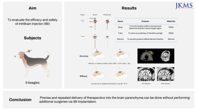
Although the current study was conducted in beagles, the IBI was designed for future clinical use. The IBI consists of three components: 1) a body with a three wing-like structure on its top, 2) a funnel shaped silicone portion that fits into the body, and 3) a tube attached to the bottom of the body, the tip of which reaches a target region in the brain. Days or weeks after the IBI is implanted into the brain, the protruding silicone of the IBI located under the scalp is localized by palpation and a trocar is inserted through the silicone. The needle (e.g., Hamilton syringe) enters the tube through the trocar and the tip of the needle advances a few millimetres beyond the tip of the tube. Once the injection is completed, the needle and trocar are retracted.
The body, which localizes the implantation site and determines direction toward the target, is fixed to the skull by screwing the three wing-like structure to the skull. The height of the IBI body is 8 mm, about the same magnitude of thickness as the human skull, and the diameter of the body is 10 mm. The tube is connected to the lower part of the body, forming a pathway to the brain tissue, and the end point is positioned near the target lesion so that repeated administrations of the therapeutic agent can be performed. The diameter (outer diameter: 1.4 mm, inner diameter: 1.2 mm) of the tube is constant, while the length varies from 20 to 90 mm depending on the distance to the target region from the skull. The silicone that fills the inside of the body was designed to prevent a pressure difference between the inside and outside of the skull and to seal the needle track once the Hamilton syringe is withdrawn, so to prevent infections from occurring.
Brain magnetic resonance (MR) images of each of the beagles were measured beforehand and the length of the tubes were adjusted accordingly. The IBI silicone-body-tube was assembled prior to implantation. Once the IBI was implanted, the silicone portion of the IBI was placed in-between the scalp and the skull which created a bulge. This convex area made it feasible to pinpoint the location to insert the syringe for the upcoming administrations.
Experimental design of IBI implantation and stem cell administration in beagles
Nine male beagles were obtained from KNOTUS Co. Ltd. (Incheon, Korea). Beagles were grouped according to the number of stem cell injections: a single injection (n = 3), three injections (n = 3), and six injections (n = 3). As illustrated in Fig. 1, to complete the study at the same end point for all three groups, beagles assigned to the six-injection group received the injections first.
 | Fig. 1Scheme of IBI implantation and stem cell administration. In each group, MRI was taken at 1) baseline (after marker screw insertion), 2) pre-injection (before stem cell administration), and 3) post-injection (after stem cell administration).IBI = IntraBrain Injector, MRI = magnetic resonance imaging.
|
Magnetic resonance imaging (MRI) protocol
Anaesthesia throughout the MRI procedure was induced with tiletamine and zolazepam (4.5 mg/kg i.m.) and xylazine (0.2 mg/kg i.m.). Beagles were positioned supinely in the MRI scanner with their head in the center of the coil. Imaging consisted of a 3D MP-RAGE sequence with the following parameters: TI 926 ms, α 8°, TE 3.47 ms, TR 2300 ms, number of averages 2, FOV 150 mm, 224 slices, and slice thickness of 0.5 mm with no gap. Scans were performed using a 3.0T MRI scanner (Magnetom Prisma; Siemens Medical Systems, Erlangen, Germany) and an eight-channel knee coil (Siemens Medical Systems).
Determination of trajectory toward the target point
To minimize damage to the hippocampus, the end point of the tube was located 5 mm away from the target, as illustrated in Fig. 2. To ensure precise positioning of the IBI tube with respect to the target structure, three 3 mm titanium screws were screwed into the skull (frontal and parietal area) of the beagles as landmarks for preoperative anatomical imaging (Fig. 2).
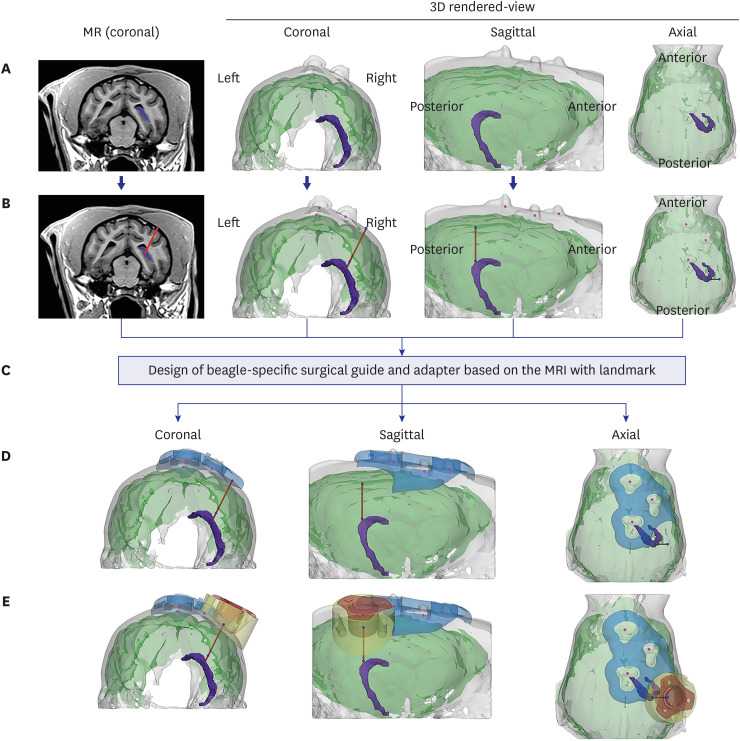 | Fig. 2Determination of insertion trajectory and design of the surgical guide and adaptor. (A) The target area (the hippocampus in this study, marked in purple) was determined based on coronal view MRI after screw insertion. To determine the ideal trajectory, 3D-rendered images of the skull and brain were reconstructed. (B) An ideal insertion trajectory was considered one that allowed insertion of the IBI into the gyrus with minimal muscle detachment. (C) The surgical guide and adaptor were designed based on the location of three marker screw landmarks on the skull, reflecting the skull curvature. (D) The surgical guide (blue) was positioned to exactly locate the drilling point of the burr hole. (E) The adaptor was positioned in line with the burr hole, not only to fill the gap between the flat bottom surface of IBI and the curved skull surface, but to prevent the IBI from invading the brain surface.IBI = IntraBrain Injector, MRI = magnetic resonance imaging, MR = magnetic resonance.
|
Two weeks after screw insertion, a second MRI scan using the same protocol described above was performed. Based on the MRI, the hippocampus and skull of the beagle were segmented to determine the appropriate trajectory taking the anatomy of each beagle into consideration. The mid-coronal plane was determined among areas containing the hippocampus in the coronal view, and the insertion trajectory from the skull to the target was determined to be the point closest to the skull surface. To minimize surgical risks, the following points were considered to determine the surgical site: 1) unlike humans, beagles have a bulky scalp muscles, thus we chose a location that would minimize muscle detachment; 2) the IBI was inserted into a gyrus rather than the sulcus to prevent possible bleeding.
Design of the adaptor and the surgical guide for precise injection targeting using 3D printing
Due to differences in human and canine skull anatomy, several adjustments were made during the implantation procedure. For example, due to the thick ear muscles of beagles, the IBI had to be positioned away from the muscles. To account for the gap that is formed in-between the body of the IBI device and skull surface, a surgical guide and adaptor was implemented into the surgical procedure (Fig. 2).
The surgical guide (Fig. 2C) was designed to mark the precise drilling point in the skull of beagles. The surgical guide was used to determine the location of the burr hole for fixation of the adaptor in the correct position and orientation. Completed design of the surgical guide was saved as an STL file. Dental SG material (Class I biocompatible resins; EN-ISO 10993-1: 2009/AC: 2010, USP Class VI) was applied for 3D-printing using SLA type Form2 (Formlabs, Somerville, MA, USA) equipment. After 3D printing was completed, the supporters were removed, and the surgical guides were washed with isopropyl alcohol followed by a hardening process.
The adaptor was designed to have a flat top to embed the IBI and a curved bottom reflecting the surface of the skull. The purpose of the adaptor was to fill the space between the IBI body and the skull of the beagle and prevent the IBI from invading the brain surface. For the pilot study, the adaptor was produced by 3D printing but in the main experiment, it was manufactured through computerized numerical control using PEEK, the same material used for the IBI. To fix the adaptor above the burr hole, three screw insertion points were selected at 120-degree intervals, and each screw was designed to be inserted perpendicularly into the skull. To embed the wing-like structure of the IBI body, the upper part of the adaptor created a groove of 320 µm.
Surgical procedure used for IBI implantation
All surgeries for IBI implantation were performed by an experienced neurosurgeon (Lee S). Anaesthesia was induced with tiletamine and zolazepam (4.5 mg/kg i.m.) and xylazine (0.2 mg/kg i.m.), followed by intubation and isoflurane (1.5–3%) maintenance throughout the remainder of the procedure. Beagles were placed in a prone position and the head of the beagles were firmly fixed in a stereotactic head holder (KOPF 1530; David Kopf Instruments, Tujunga, CA, USA). Hairs on the head were shaved and the skin was wiped with povidone-iodine and the surgery site was draped. After a minimal midline skin and muscle incision (Fig. 3A) was made, the sterilized 3D printed surgical guide was applied to the surface of the skull and a burr hole, 14 mm in diameter, was drilled and the dura was incised to expose the surface of the brain (Fig. 3B and C).
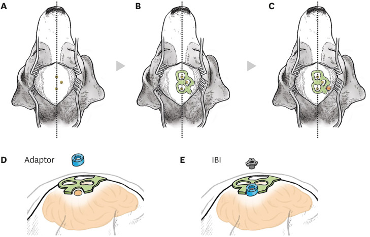 | Fig. 3Surgical procedures for IBI implantation in beagles. An illustration of operational procedures for the IBI. (A) Skin and muscles above the skull were incised minimally along the midline. Location of the screws on the skull that had been installed before IBI implantation was confirmed. Beagles were placed on a stereotaxic frame for the surgery. (B) A 3D-printed surgical guide (coloured in green) was placed on the skull, according to the location of marker screws. (C) Using the surgical guide, a burr hole (coloured in red) was drilled. (D) A round-shaped adapter (coloured in blue) was anchored above the burr hole. (E) The IBI was placed on the adapter.IBI = IntraBrain Injector.
|
The adapter was anchored in line with the burr hole (Fig. 3D). The length of the IBI tube was calculated before the operation based on the calculated depth from the skull to the target point using preoperative MRI. Using a guiding rod to reach the target without bending, the IBI was introduced to the target at a rate of 1 mm per minute following the calculated optimal trajectory. When the upper body part of the IBI reached the adapter, the IBI was implanted on the adapter and the guiding rod was retracted (Fig. 3E). Afterwards, the surrounding muscles, fasciae, and skin were sutured. All surgical procedures were performed aseptically within 2 hours. Following the surgery, a warm blanket was placed on the subject to allow recovery. The temperature, pulse, and respiration were recorded additionally.
Confirmation of IBI placement after implantation
To further quantify IBI placement, we calculated the match between the planned and inserted trajectories using pre-administration MRI. The match between the planned and actual injected trajectories of the tube was evaluated by 1) comparing the distance between the point of the insertion entry point to the planned entry point and 2) determining cosine angle similarity between the two vectors as shown in the equations below.


Blood collection and analysis
To monitor the safety of IBI implantation, blood was collected before the baseline and before every cell injection: seven times for group 1 (six injections), four times for group 2 (three injections), and twice for group 3 (single injection). Complete blood count (CBC) parameters of whole blood, collected in EDTA anticoagulant, were measured in all beagles using an automated hematology analyzer (ProCyte DX® haematology analyser; IDEXX Laboratories, Inc., Westbrook, ME, USA).
Administration of ferumoxytol-labeled human umbilical cord blood-derived mesenchymal stem cells (hUCB-MSCs)
hUCB-MSCs (Biomedical Research Institute, MEDIPOST Co., Inc., Seongnam, Korea) were cultivated according to a good manufacturing practice protocol and were continuously checked to confirm that they met the International Society for Cellular Therapy guidelines. Passage 6 hUCB-MSCs were labeled with ferumoxytol (Rienso®; Takeda Inc., London, UK) as previously described.2122 Ferumoxytol-labeled hUCB-MSCs (5 × 10⁵ cells) were suspended in 30 μL of phenol red free MEMα media (Gibco, Waltham, MA, USA) before administration.
The exact position of the IBI was easily detected due to the convex silicone part of the IBI, and the trocar was inserted through a silicone disc. A 100 µL Hamilton syringe (syringe length 100 mm, customized; Hamilton Company, Reno, NV, USA) was injected 5 mm deeper than the end of the tube and ferumoxytol-labeled hUCB-MSCs were injected at a rate of 3 μL/min. The stopper was used for the precise injection depth calculation. The length of stopper was decided by calculating the tube length and height of IBI for each subject.
All beagles underwent MRI before (pre-injection MRI) and after (post-injection MRI) MSC administration. The success of the injection was determined by whether paramagnetic signals created by ferumoxytol-labeled MSCs were observed at the injection site. All images were evaluated according to the following criteria: 1) precise injection defined by signals detected at the target area (hippocampus), 2) satisfactory injection defined by signals detected within 2 mm of the target area, 3) failed injection defined by signals detected further than 2 mm from the target area or uncertain signals. Rating was performed independently by an experienced neurologist (Jang H) and a neuroradiologist. Interrater reliability was high. When there was a discrepancy between the raters, a consensus was reached after discussion.
Ethics statement
All experimental procedures were reviewed and approved by the Institutional Animal Care and Use Committee (study approval number: 20161212-001) of the Laboratory Animal Research Center (LARC) at Samsung Medical Center (SMC). The LARC at SMC, as an accredited facility of the Association for the Assessment and Accreditation of Laboratory Animal Care International, abides by the Institute of Laboratory Animal Resources guidelines.
Go to :
RESULTS
Target accuracy of IBI implantation
As illustrated in Fig. 4A-C, IBI tubes were accurately implanted in the cerebral cortex of all nine beagle subjects. The average distance and cosine similarity between the two trajectories were found to be 1.04 ± 0.56 mm and 0.990 ± 0.001 (mean ± standard deviation), respectively.
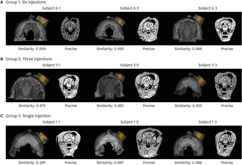 | Fig. 4Validation of target approach accuracy. Validation of target accuracy is shown in 3D rendered views and coronal MRI in (A) group 1 (six injections), (B) group 2 (three injections), and (C) group 3 (single injection). The white arrow shows a signal indicative of haemorrhage after surgery in the MRI of Subject 6-1.MRI = magnetic resonance imaging.
|
Surgery-related safety
Of the nine surgeries performed, only one surgery (in subject 6-1) resulted in hemorrhage that was located at the end of the IBI tube (shown in Figs. 4A and 5A). There were no abnormal behaviors or symptoms discernible after IBI implantation in any of the beagles, including the beagle that developed a hemorrhage. The hemorrhage disappeared by the time the second pre-injection MRI was performed a month later.
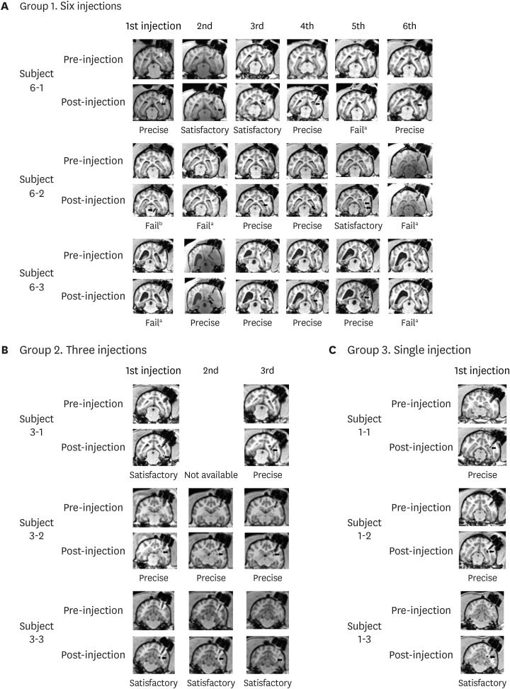 | Fig. 5MRI used for evaluation. MRI results of pre- and post-injection in (A) six-injection group, (B) three-injection group, and (C) single injection group.MRI = magnetic resonance imaging.
Failed results marked with superscript ‘a’ indicate an uncertain signal and those marked with superscript ‘b’ indicate signals detected further than 2 mm from the target area.
|
We also monitored the long-term safety of IBI implantation using laboratory tests. CBC and differential counts were within normal ranges with the exception of the first and second CBC results in group 1, which were mildly low. These lower values were not seen in the third test, indicating that the previous abnormal results were not caused by implantation of the IBI (Table 1).
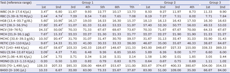
Table 1
Complete blood count results for the three groups of beagles
Group 1 = six injection group (n = 3), Group 2 = three injection group (n = 3), Group 3 = single injection group (n = 3).
WBC = white blood cells, RBC = red blood cells, HGB = haemoglobin, HCT = haematocrit, MCV = mean corpuscular volume, MCH = mean corpuscular haemoglobin, MCHC = mean corpuscular haemoglobin concentration, RETIC = reticulocyte count, PLT = platelet count, NEU = neutrophil count, LYM = lymphocyte count, MONO = monocyte count, EOS = eosinophil count, BASO = basophil count.
*Complete blood count results that had slightly lower values than the reference range.
![]()
Imaging confirmation of repeated ferumoxytol-labeled MSC injections
A total of 30 MSC injections were performed: six injections in three beagles (Fig. 5A, 18 times), three injections in three beagles (Fig. 5B, 9 times), and a single injection in three beagles (Fig. 5C, 3 times).
According to the criteria described in Methods, 23 out of 30 injections were rated as precise (15/23) or satisfactory (8/23), corresponding to a success rate of 76.7%: 12 out of 18 (66.7%; precise 9/12, satisfactory 3/12) in the six-injection group, 8 out of 9 (91.7%; precise 4/8, satisfactory 4/8) in the three-injection group, 3 out of 3 (100%; precise 2/3, satisfactory 1/3) in the single injection group. Overall, as injections proceeded over time, the failure rate decreased.
Six-injection group
The group that received six injections and that had been operated on at the beginning of the experiment had the highest failure rate. MR signals were not identified from subject number 6-1, the beagle that developed a hemorrhage, after the fifth administration of cells. We assumed that the cells had been injected into the lateral ventricle not the hippocampus. MR signals were detected near the midbrain of subject number 6-2 after the first injection and the cortex after the second injection; these failures were attributed to miscalculation of the injection depth. All of the administrations were successful for subject number 6-3 except the first administration, which we assumed that the cells were injected into the lateral ventricle.
Go to :
DISCUSSION
In this current study, we have developed a novel implantable medical device that involves not only a facile but also accurate administration of biopharmaceuticals into the brain parenchyma. The widely used Ommaya reservoir system can only be used to perform injections into the CSF. IBI system, in contrast, can be utilized to repeatedly inject therapeutic agents into the brain parenchyma without performing additional operations for each injection. Although the delivery of stem cells was highlighted in this present study, IBI is a versatile device that can be applied to deliver a wide variety of therapeutic genes and proteins. Biopharmaceuticals injected into the brain parenchyma may exert different therapeutic effects depending on the site of transplantation. Thus, it is imperative that the administration is precisely performed at the target site or lesion area.
As summarized in Table 2, several groups have invented microinjection devices to deliver therapeutics into the brain.2324252627 These devices share features that enable administration of therapeutics to multiple regions in the brain via a single needle penetration. The IBI also offers this advantage, but the IBI possesses certain features that uniquely sets it apart from the previously reported devices. First, once implanted, the IBI can be used to repeatedly deliver therapeutics to a specific target site for a long period of time. Thus, IBI may serve beneficial roles in chronic neurodegenerative diseases which may require repeated infusions of therapeutics.2829 Previously reported devices, on the other hand, require surgical operations for each administration which is not only costly and inconvenient for patients but also increases the risks of possible side effects such as hemorrhages or infections. A group, however, has reported on a device that allows repeated convection-enhanced delivery via a microfluidic system.27 A microfluidic pump might be ideal to perform administrations of a continuous but limited amount of chemical drugs,30 but it may not be suitable to administer biopharmaceutical agents, such as cells. Another attractive feature of the IBI is that due to its straight end, the device is not only easier to handle but it also allows precise injections to be made at the target site. It will be difficult to achieve precise targeting when using devices with curved ends.24 Lastly, previous devices have been designed to be compatible with a stereotactic frame,232526 but the IBI was designed to be used with a stereotactic navigation system. Not incorporating stereotaxic frames into the surgical operation may serve beneficial purposes. For example, fixating a heavy stereotactic frame during pre-operative examinations and the surgical procedures may cause pain and discomfort for patients.31
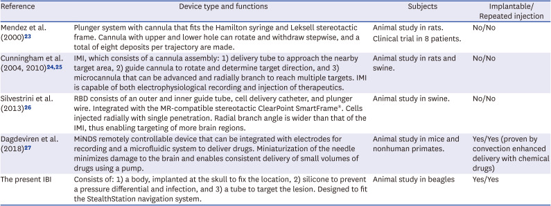
Table 2
Summary of the type and function of previously reported medical devices and the IBI
| Reference | Device type and functions | Subjects | Implantable/Repeated injection |
|---|---|---|---|
| Mendez et al. (2000) 23 | Plunger system with cannula that fits the Hamilton syringe and Leksell stereotactic frame. Cannula with upper and lower hole can rotate and withdraw stepwise, and a total of eight deposits per trajectory are made. | Animal study in rats. | No/No |
| Clinical trial in 8 patients. | |||
| Cunningham et al. (2004, 2010) 24 , 25 | IMI, which consists of a cannula assembly: 1) delivery tube to approach the nearby target area, 2) guide cannula to rotate and determine target direction, and 3) microcannula that can be advanced and radially branch to reach multiple targets. IMI is capable of both electrophysiological recording and injection of therapeutics. | Animal study in rats and swine. | No/No |
| Silvestrini et al. (2013) 26 | RBD consists of an outer and inner guide tube, cell delivery catheter, and plunger wire. Integrated with the MR-compatible stereotactic ClearPoint SmartFrame®. Cells injected radially with single penetration. Radial branch angle is wider than that of the IMI, thus enabling targeting of more brain regions. | Animal study in swine. | No/No |
| Dagdeviren et al. (2018) 27 | MiNDS remotely controllable device that can be integrated with electrodes for recording and a microfluidic system to deliver drugs. Miniaturization of the needle minimizes damage to the brain and enables consistent delivery of small volumes of drugs using a pump. | Animal study in mice and nonhuman primates. | Yes/Yes (proven by convection enhanced delivery with chemical drugs) |
| The present IBI | Consists of: 1) a body, implanted at the skull to fix the location, 2) silicone to prevent a pressure differential and infection, and 3) a tube to target the lesion. Designed to fit the StealthStation navigation system. | Animal study in beagles | Yes/Yes |
IBI = IntraBrain Injector, IMI = intracranial microinjection instrument, RBD = radially branched deployment, MR = magnetic resonance, MiNDS = Miniaturized Neural Drug Delivery System.
![]()
The first goal of this study was to confirm the successful and accurate implantation of the IBI. We observed the correct placement of the tip of the IBI tube at the site of interest. We also checked that the IBI tube was aligned with the hippocampus so that when the Hamilton syringe was advanced through the IBI tube, the syringe was able to reach the hippocampus. Neurosurgery with cranial perforation is usually performed on a stereotactic navigated platform combined with brain images of patients.32 The IBI is compatible with the Medtronic Stealthstation® (Medtronic Navigation, Inc., Louisville, CO, USA) which allows the IBI tube to be successfully guided towards the precise target point. In this study, however, a 3D-printed surgical guide and adaptor system were used instead of a navigation platform due to the difference in the length of the IBI body and the skull depth of beagles. To account for the curvature of the skull surface, the implementation of the adaptor system allowed for the IBI to be tightly attached to the skull. MR images acquired after implantation demonstrated that the adaptor system aided the precise placement of the IBI. The IBI tube was implanted in the vicinity of the target site to prevent damage. A syringe needle was inserted into the IBI tube to administer cells into the hippocampus. The surgical system (the surgical guide and the adaptor) that we have developed in this current study can be also be used in animal studies, especially when a neurosurgical navigation is unavailable.
The second major focus of our study was to determine the safety of the IBI implantation and the repeated injection of cells. Out of the nine implantation surgeries that were performed, only one subject developed a hemorrhage (11.1%, 1 in 9 cases). No apparent behavioral symptoms were observed following the hemorrhage and signs of the hemorrhage were not visible from the MR images acquired a month later. Second, none of the 30 separate cell injections generated abnormal MR signals indicative of hemorrhage or inflammation (3.3%, 1 in 30 cases; first hemorrhage expected to be the result of surgical procedure). We also verified that there was no subcutaneous inflammation such as local swelling or abscess associated with each cell injection. Finally, no severe adverse reactions or abnormal behavior were noted in any of the beagles after long term placement of the IBI (up to 6 months). CBC tests results confirmed that no inflammatory responses were generated after IBI implantation.
The final major concern of this study was to observe the accurate and precise transplantation of MSCs to the target site. Out of 30 injections, 15 injections were considered precise and MR signals were detected within 2 mm of the hippocampus for eight injections. The overall success rate was 76%. Out of seven injections that were considered failed administrations, 6 occurred in the early stages of our experiment, and the success rate increased over time, with a 100% success rate achieved near the end of the study. The most common cause of failure (6/7) was miscalculation of injection depth. Although the IBI tube provides a pathway to the lesion, cells are injected to the target site by a syringe advanced through the end of the tube. Therefore, it is necessary to adjust the injection depth of the syringe to repeatedly administer the cells to the same location. To overcome this problem, we devised a needle stopper system that limited the injection depth range of the syringe. This also increased the overall accuracy of the administration. Since the IBI device was inserted vertically into the parenchyma of the beagle brain, there is a possibility that the syringe may have penetrated the lateral ventricles. Upon penetration, cells may have been exposed to the CSF thus the cells may have been washed out due to the CSF flow. This might have accounted for the absence of MR signals from the ferumoxytol-labeled MSCs. Due to the advanced stereotactic navigation system used widely in the clinical setting, we expect higher success rates when IBI is applied clinically for human subjects.
Several issues were encountered in this study. Since the IBI can only be inserted vertically through the skull surface, the IBI could not be used to target widespread regions of the brain but specific sites of the brain parenchyma. To implement this vertical approach, the position of the burr hole also had to be modified so that major blood vessels will remain unharmed when implanting the IBI. Another issue that we encountered was that when the degree of skull surface curvature was high, due to the gap that formed in-between the device and skull surface, it was difficult to accurately position the IBI and the adaptor. To address this limitation, we are currently in the process of creating a new IBI device with angle adjustable features.
In the present study, we examined the feasibility and safety of utilizing the newly developed IBI to administer therapeutics repeatedly into the brain parenchyma. By performing the study using a large animal model (beagles), we also sought to assess the potential of the IBI device for clinical translation. We believe that the 3D printed surgical system used in this study can serve useful purposes for neurosurgical practice.
Go to :
 XML Download