Abstract
New digital technologies, many involving three-dimensional printing, bring benefits for clinical applications. This article reports on the clinical procedure and fabrication of a skeletally anchored mesialization appliance (Mesialslider) using computer-aided design/computer-aided manufacturing (CAD/CAM) for space closure of a congenitally missing lateral incisor in a 12-year-old female patient. The insertion of the mini-implants and appliance was performed in a single appointment. Bodily movement of the molars was achieved using the Mesialslider. Anchorage loss, such as deviation of the anterior midline or palatal tilting of the anterior teeth, was completely avoided. CAD/CAM facilitates safe and precise insertion of mini-implants. Further, mini-implants can improve patient comfort by reducing the number of office visits and eliminating the need for orthodontic bands and physical impressions.
Congenitally missing maxillary lateral incisors and traumatic tooth loss are the most frequent reasons for spaces in the maxillary anterior region among adolescents.1 The absence of these teeth can be either uni- or bilateral. When planning the therapy, each practitioner must decide how to treat these spaces in the long-term as there are two major treatment approaches.2,3 One option is to maintain or to open the space for later prosthodontic replacement with a single-tooth implant or fixed prosthesis.4 However, single-tooth implants can compromise the long-term aesthetics of the maxillary anterior region due to ongoing alveolar ridge growth and bone remodeling resulting in increasing infraposition.5,6 Therefore, in many cases, orthodontic space closure seems desirable and treatment can be started as soon as the dentition is complete.7-9 The demands for anchorage quality will be higher compared to those for space opening.10 Maintaining the sagittal overbite and avoiding deviation of the anterior midline requires excellent anchorage, especially when the space is asymmetrical and the more mesial the missing tooth is. Intraoral anchorage by means of intermaxillary elastics is frequently used, but its success is highly dependent on patient compliance. Another drawback of this technique is the distally directed force on the mandibular dentition, which results in retrusion of the mandibular anterior teeth.
A compliance-independent appliance that anchors itself exclusively in the maxillary dentition would therefore be desirable for space closure to avoid retrusion of the mandibular teeth. The use of skeletal anchorage has increased in recent years not only because of its independence from patient compliance but also due to the need for more reliable anchorage.11 For mesialization in the maxillary jaw, the Mesialslider in particular has become increasingly well established.12-17 Three-dimensional (3D) evaluation of space closure using the Mesialslider has shown that there was no adverse change in the anterior tooth position after space closure with an average molar movement of 6.3 mm.18 The advantages of using mini-implants in the anterior palate (T-zone) region are the good bone quality, high success rate without risk of tooth injury, and ability to move all teeth in the dental arch using temporary anchorage devices (TADs) without any interference.19
New digital technologies are increasingly being incorporated into the practice of orthodontics. Many workflows have already been successfully digitalized, including that for mini-implants and the production of superstructures.20 Until recently, the manufacturing of appliances involved a classical laboratory process with band fitting, physical impression taking, production of a study model, and subsequent construction of the appliance using prefabricated components.12 Due to improvements in intraoral scanners and their increasing reliability as well as the emerging developments in the field of additive manufacturing, digital computer-aided design/computer-aided manufacturing (CAD/CAM) workflows have been successfully applied for the production of orthodontic appliances, such as maxillary expanders and fixed retainers.21,22 This article reports on the application of these technologies for the manufacturing of a mini-implant-supported Mesialslider.
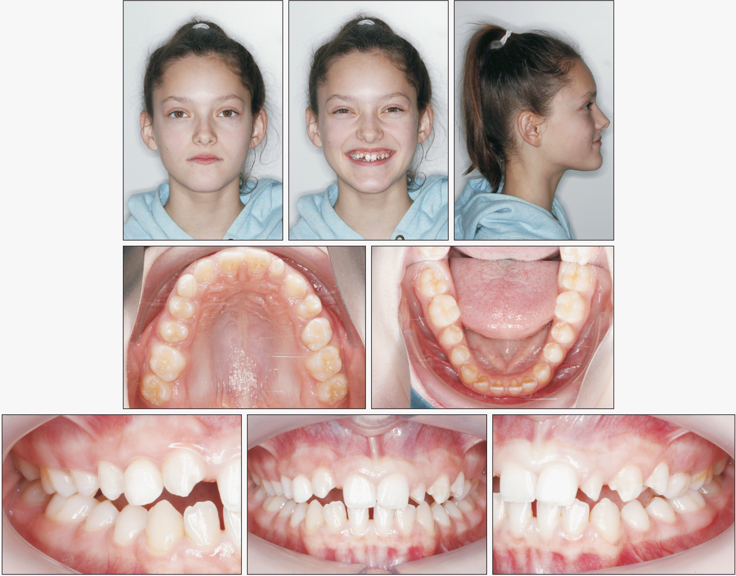
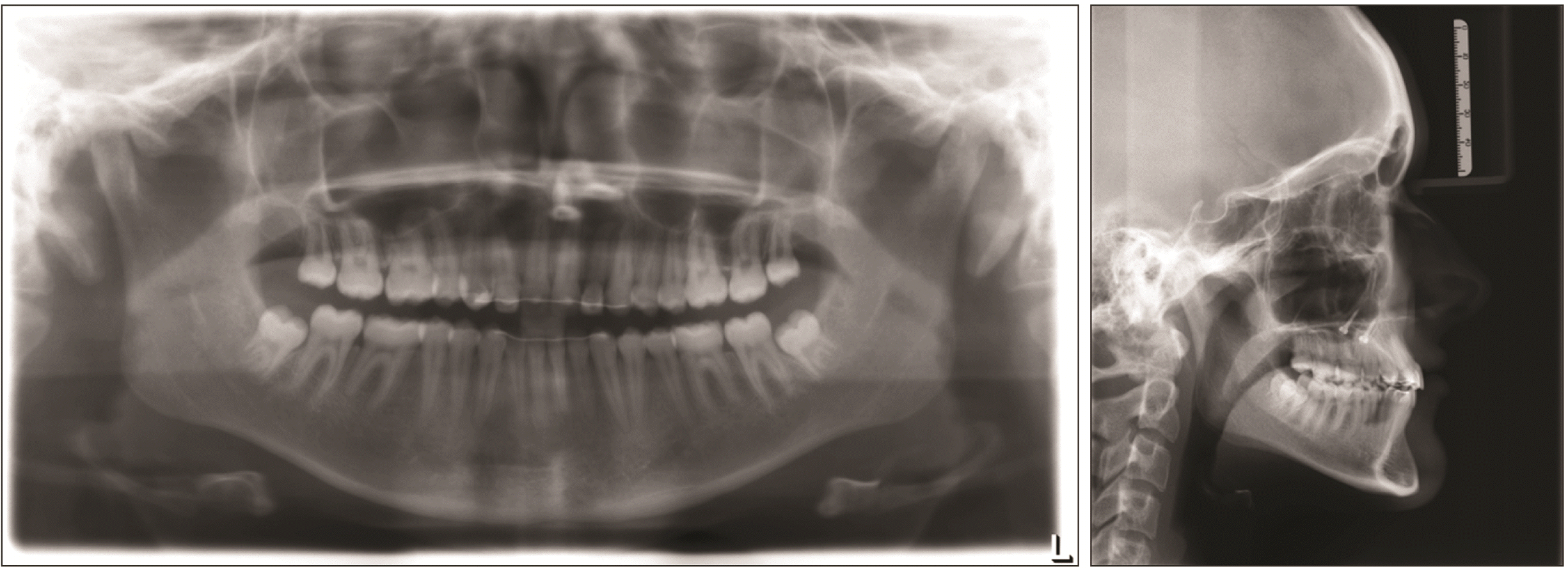
A 12-year-old healthy female patient in the permanent dentition presented with a Class I malocclusion, agenesis of the maxillary right lateral incisor, a retained right deciduous canine, and a high smile line (Figure 1). The maxillary left lateral incisor was diminutive with generalized microdontia resulting in generalized spaces in both arches. Radiographs (panoramic and periapical radiographs) revealed the presence of all wisdom teeth and advanced root resorption of the deciduous canine (Figure 2).
A written informed consent was obtained from the patient for the publication of this case report.
The treatment objectives were to level and align both arches, extract the deciduous canine, achieve space closure by mesialization of the right quadrant, and obtain a therapeutic unilateral Class II molar relationship.
The treatment alternative involved preservation of the deciduous canine and keeping the space open for implant placement in the future. Given the questionable prognosis of the tooth, which was likely to be lost soon, and considering the young age of the patient, it would have been too early for space opening; the alveolar ridge would have probably atrophied to a significant degree due to the lack of function by the time implantation was possible. The patient and her family agreed to the unilateral mesialization of the maxillary posterior teeth for orthodontic space closure. For aesthetic reasons, restorative enhancement of the diminutive left lateral incisor with composite build-ups, as well as remodeling of the maxillary right canine and first premolar, according to the “camouflage concept" given by Rosa and Zachrisson23 were planned. The first premolar was remodeled into a canine and the canine into a lateral incisor. In addition, intrusion of the first premolar and extrusion of the canine were planned to harmonize the gingival line along with reshaping of the canine by inter-proximal and incisal grinding.
The maxillary arch and palate were recorded with a TRIOS intraoral scanner (3Shape, Copenhagen, Denmark) and the resulting stereolithography (STL) file was uploaded to Blender (open-source software, Blender Foundation, Amsterdam, Netherlands), which provided the option of merging the file with either a cone beam computed tomography (CBCT) or a lateral cephalometric radiograph. In this case, we used the available cephalometric radiograph. The patient scan and radiograph were superimposed by positioning of the central incisors on top of each other: the 3D model was split along the raphe median plane and then moved and rotated in transparent mode on the lateral cephalogram until the axis inclination and width of the upper incisors matched. This matching can be performed either using Blender or using a commercial software like TADmatch (OrthoLox, PROMEDIA, Siegen, Germany).
Our Blender database maintains previously scanned STL files of mini-implants of different lengths. The optimum implant length and sites for placement were identified based on the superimposed radiograph and scanned maxillary arch (Figure 3). For this case, two 2 × 9 mm mini-implants with exchangeable abutments (Benefit system, PSM Medical Solutions, Gunningen, Germany) were selected and placed in the midline of the anterior hard palate. Accordingly, an insertion guide was digitally designed using Blender and printed with a 3D printer (Formlabs, Somerville, MA, USA). The printing material used was Formlabs Form 2, Dental SG Resin, which is sterilizable. Any deviations in this step or in the final fabrication or positioning of the insertion guide may lead to inaccuracies making insertion of the appliance difficult or even impossible. Therefore, the lumen of the guide was checked by the dental technician for freedom of movement and further polished with a coarse diamond cylinder to reduce any resistance to sliding (Figure 4). A resulting minimal deviation in the accuracy of the surgical guide is negligible because the subsequent superstructure also has a certain tolerance due to the hyrax rings compared to rigid implant abutments.
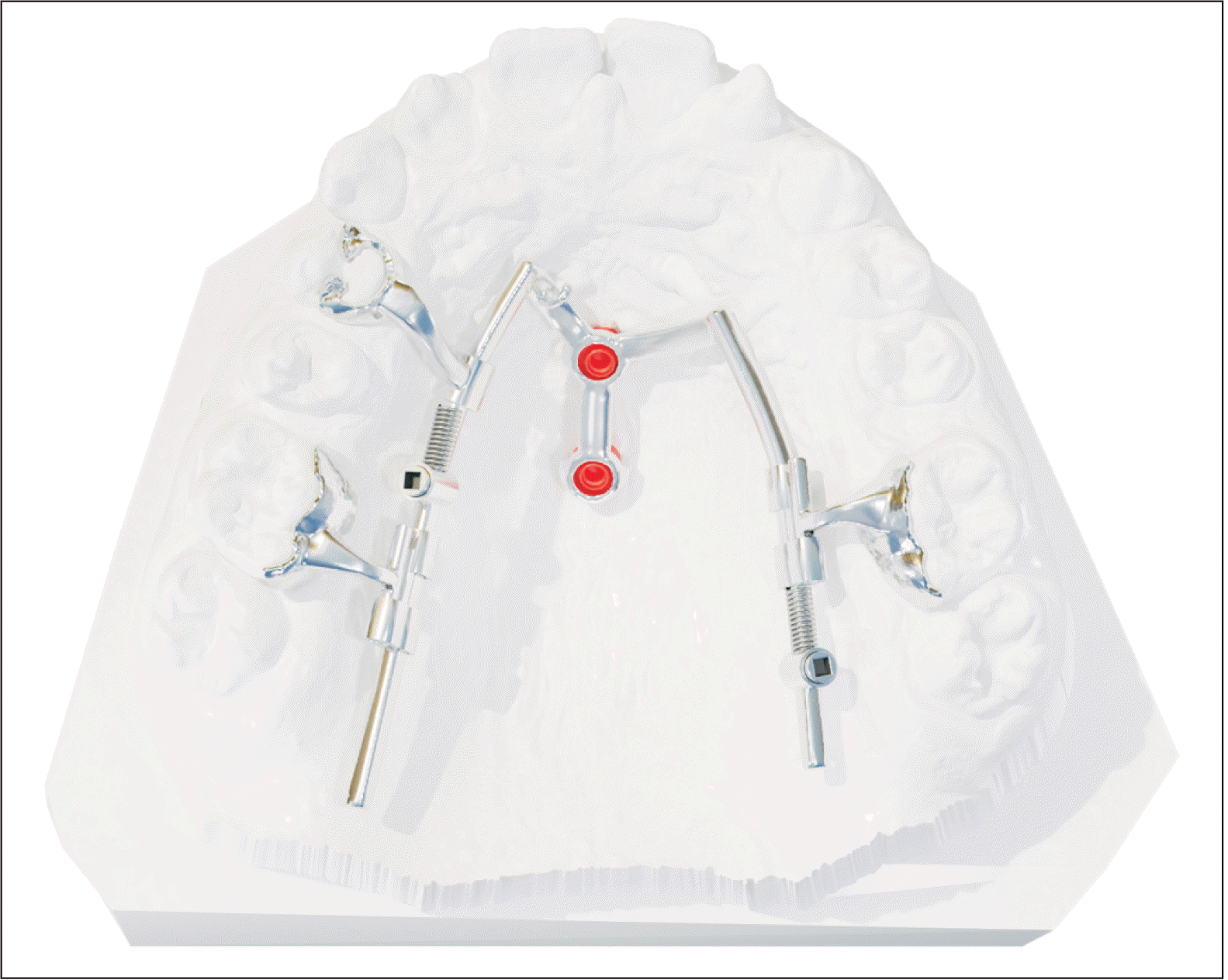
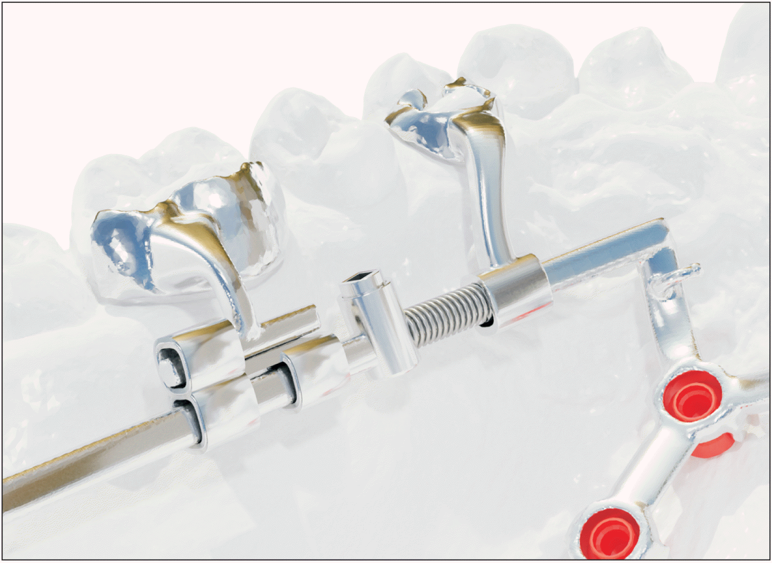
The whole appliance was designed with Blender. No other add-on module was needed except for the implant library, which was shared by the implant producer (Benefit system, PSM Medical Solutions). The CAD/CAM Mesialslider consisted of a rectangular sliding arch (1.2 × 1.4 mm) for precise guidance control and semicircular rings called shells, functioning as orthodontic bands, which were attached to the maxillary first molars and the right first premolar (Figure 5). Each shell was positioned 0.05 mm from the tooth surface to allow space for the application of the bonding adhesive. Coupling between the tooth and slider was achieved using Versalock tubes (TADMAN, Gunningen, Germany) (Figure 6).24 The appliance was attached to the implants using round, flat rings (hyrax rings) of the same height and diameter as the mini-implant neck.
The final digital design was sent to a lab with a laser-melting machine, in which the main portion of the appliance was 3D printed with a Concept Laser (Concept Laser GmbH, Lichtenfeld, Germany) with Cobalt-Chrome-Remanium star metal alloy (Dentaurum GmbH and Co. KG, Ispringen, Germany). The laser-melting process involved the application of metal powder in several thin layers by the coater and subsequent laser melting until the entire structure was finished. Finally, the structures of the Mesialslider were polished by a dental technician and the bonding bases were roughened by sand-blasting (Figure 7).
The insertion of the mini-implants and of the appliance was done using a single-appointment workflow: after surface and local anesthesia, the self-drilling mini-implants were placed using the insertion guide. Usually predrilling is not necessary, but if an insertion guide is used, especially in adult patients with high bone density, predrilling is recommended in order to reduce the possibility of axial implant deviations. A screwdriver with a stop function is recommended for inserting mini-implants using a surgical guide so that the screwdriver automatically stops at the upper edge of the guide (Benefit system, Screwholder with stop, 33-10903, PSM Medical Solutions). This prevents the implants from being inserted too deeply.
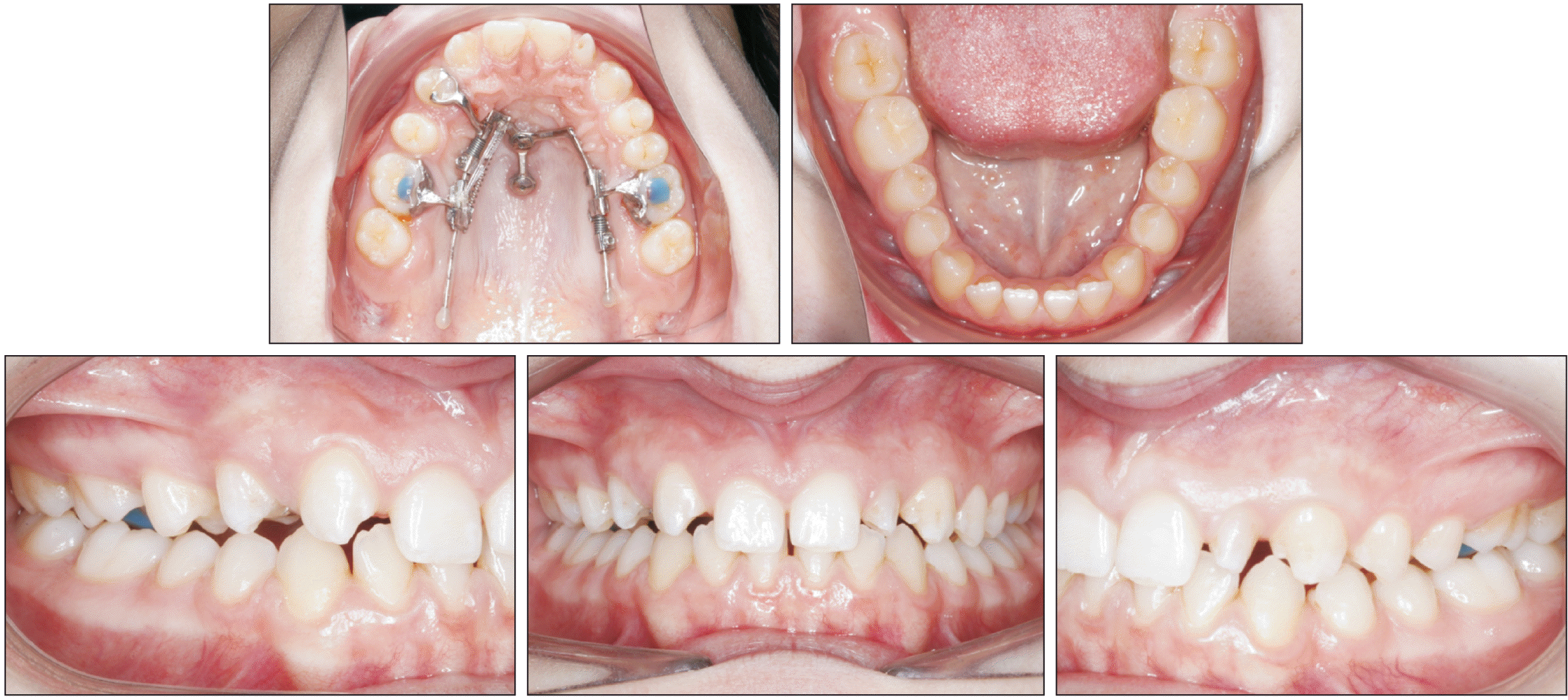
The Mesialslider was securely attached to the mini-implants with fixation screws and the shells were adhesively bonded to the palatal surfaces of the teeth using Transbond (3M Unitek, Monrovia, CA, USA). The appliance was then activated with nickel-titanium closing springs (240 g) (Figure 8). Follow-up appointments were scheduled every four to six weeks. After five months of treatment, space closure in the anterior region was almost completed (Figure 9), and the composite restoration of the diminutive maxillary left lateral incisor was finalized.
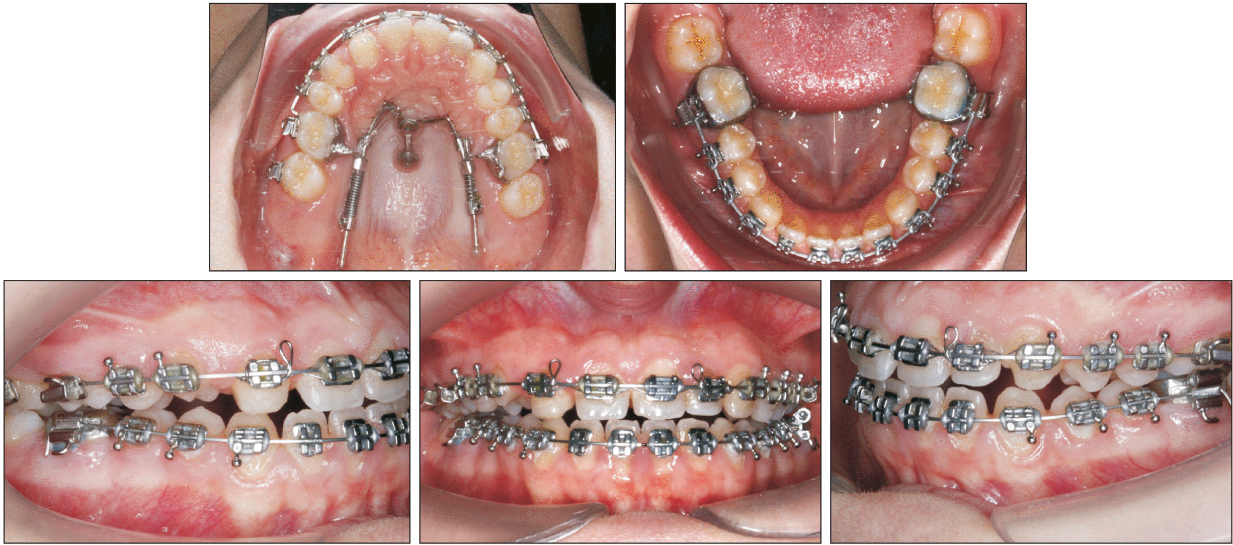
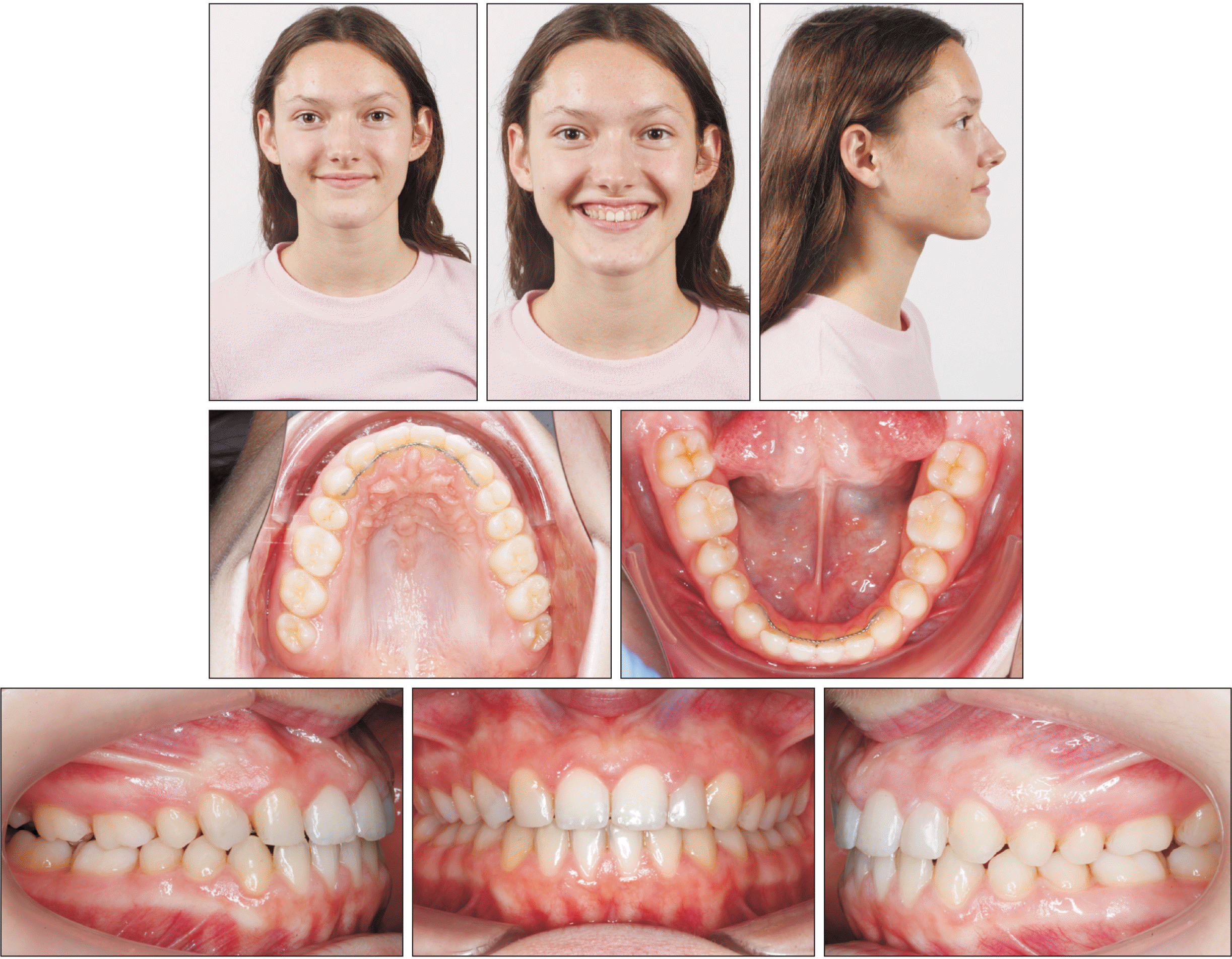
The multibracket appliance (Discovery Brackets, 0.018-inch [in] slot Roth system, Dentaurum) was inserted eight months after the start of treatment. In accordance with the "camouflage concept," a canine bracket was bonded to the right first premolar and a lateral incisor bracket to the right canine for the appropriate torque values.4,8,23 The brackets were positioned so that intrusion of the premolar and extrusion of the canine could occur during leveling to ensure correct gingival alignment (Figure 10). The canine was reshaped by approximal and incisal grinding in two sessions and the intruded premolar was built up with composite. To facilitate final occlusal settling, short vertical elastics were worn while finishing on a 0.017 × 0.025-in titanium-molybdenum archwire. The brackets were debonded after a total treatment time of less than 24 months; an appropriate overjet and overbite were achieved (Figures 11 and 12).
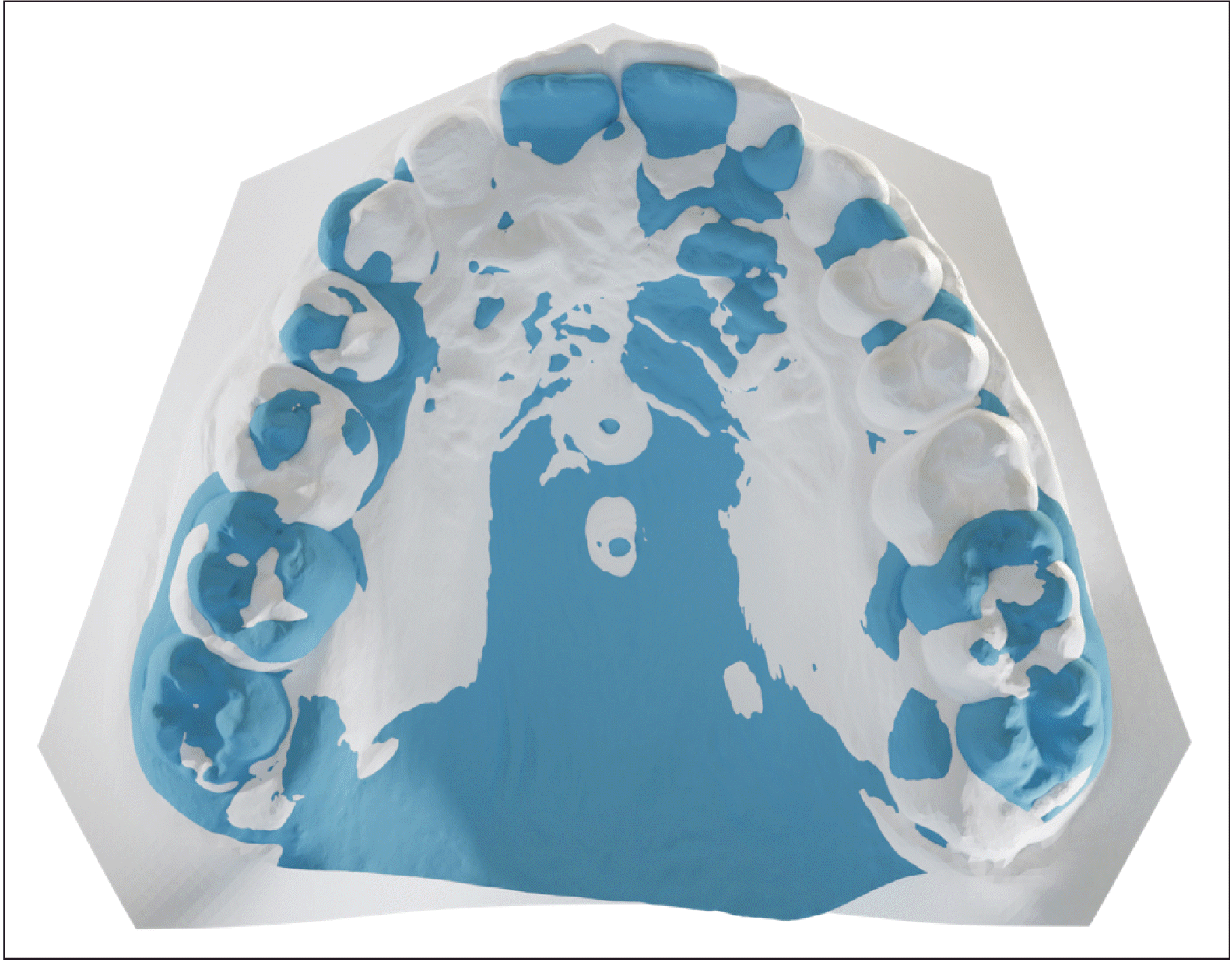
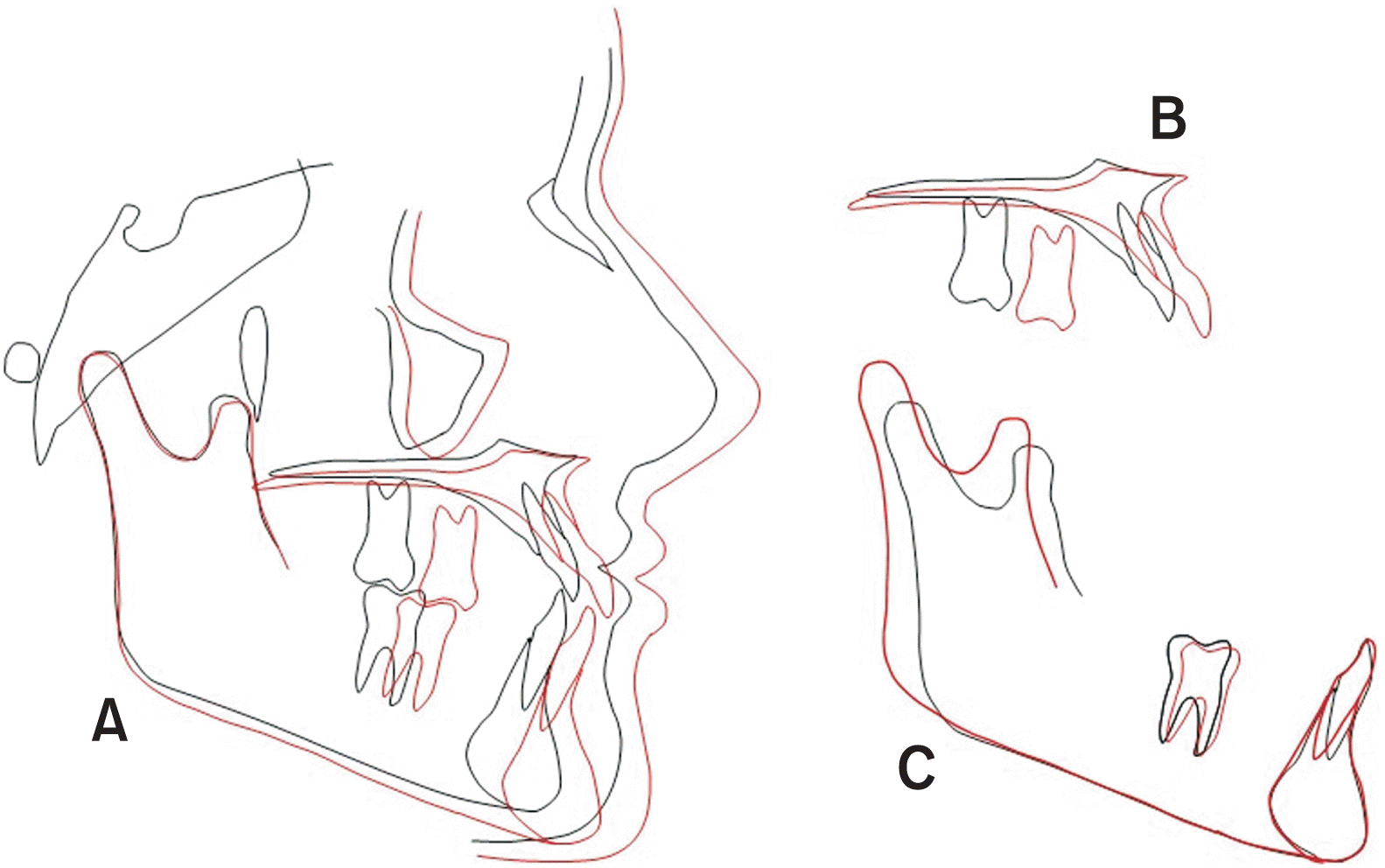
The virtual superimposition of the pre-treatment condition (blue) with the final outcome (white) showed bodily mesialization of the posterior teeth in the first quadrant (Figures 13 and 14). The sliding friction or binding in the archwire-slot interplay of the fixed appliance led to mild proclination of the maxillary anterior teeth, a so-called reverse anchorage loss. The position of the mini-implants remained unchanged. The torque of the maxillary right canine and first premolar was not fully corrected to the normal torque of lateral incisor and canine. To achieve a greater torque, additional treatment time for finishing or aesthetic porcelain restorations with veneers would have been necessary. However, the patient and the family were very satisfied with the result and wished no further treatment.
The treatment of anterior spaces is a challenge for every dentist because both treatment options, orthodontic space closure and prosthetic rehabilitation, have their pros and cons.5,6,25 Due to vertical alveolar ridge growth and bone remodeling that continues long into adulthood, it is often observed that single-tooth implants develop an infraposition that compromises aesthetics, especially in the maxillary anterior region.5,6 However, orthodontic closure also has its disadvantages: this treatment usually takes longer than space opening. In addition, there are usually high anchorage demands to prevent undesirable tooth movements, such as excessive retraction or palatal tilting of the anterior teeth or midline deviation in the case of unilateral space closure. The use of TADs guarantees better anchorage making one-sided space closure possible and predictable. The virtual superimposition of the pre-treatment condition with the final outcome in this case report showed bodily mesialization of the posterior teeth in the first quadrant (Figures 13 and 14). However, to confirm that there was no anchorage loss after posterior mesialization, it would be important to compare the pre-treatment condition with the immediate outcome after space closure. Otherwise, possible anchorage loss could have been corrected by the use of the fixed appliance. We did not have patient records from before the insertion of braces, which is a limitation of this case report.
The use of the anterior hard palate and direct anchoring by means of Mesialsliders are highly reliable in everyday clinical practice due to its high success rate and compliance-independence.18 After complete space closure, detailed finishing is key to achieving an aesthetic outcome. Harmonized gingival contours can be obtained by vertical leveling of the anterior teeth.4 The canine can be extruded and the first premolar can be intruded to mimic the natural gingival line.26
Studies have shown that the occlusal function and periodontal status after orthodontic space closure and vertical adjustment showed excellent long-term stability.8 A further advantage of space closure is that new bone can be generated in the area of the missing teeth through tooth movement. The clinical impression is that the teeth “take their bone with them." Bone atrophy in edentulous spaces can therefore be corrected.27-33 Last but not least, existing wisdom teeth often drift mesially after mesialization of the molars due to the interdental fibers and subsequently find sufficient space in the dental arch.
The complete digital workflow, from TAD insertion planning to appliance design, could be implemented in orthodontic implantology. The simultaneous digital manufacturing of the insertion guide and superstructures (in this case Mesialslider) allows the insertion of mini-implants and skeletal appliances in only one session (single-appointment workflow). Practitioners seeking a safe introduction to treatment with mini-implants often prefer insertion with an insertion guide based on radiographic diagnostics (CBCT or lateral cephalometric radiograph) (Figure 3). Digital workflows can potentially be applied for patients with a cleft palate, where bone availability in the anterior palate is unpredictable without CBCT guidance. When using a single-appointment workflow, specific attention must be paid to a precise insertion of the mini-implants, since small axial deviations of the implants can make insertion of the orthodontic appliance difficult if not impossible.
The CAD/CAM designed Mesialslider features an enlarged rectangular cross-section to optimize tooth movement and controlled guidance of the molars through the alveolar process. In addition to the change in cross-section, the Cobalt-Chrome-Remanium star metal alloy used for manufacturing (E-modulus: 220 GPa) also ensures a significant increase in the dimensional stability of the 3D-printed mesialslider compared to spring-hard steel (E-modulus: 180 GPa), which is used in conventionally manufactured sliders.
The coupling between the guiding bar and the tooth is achieved by means of the newly developed Versalock tubes.24 This new development is based on the clinical experience that conventional palatal locks easily deform during use and therefore no longer offer sufficient torque control after only a short time. The coupling between tooth and appliance takes place at the level of the resistance center and thus supports physical tooth movement. The flexible design allows the distalization or mesialization distance to be extended if the guiding bar does not allow sufficient movement distance.
Some studies indicate that implants close to the third rugae or even further anterior may have a higher risk of penetrating the canalis incisivus, which could damage the nasopalatine bundle.34,35 In general, the further posterior the insertion, lesser the risk of penetration. Previous publications have shown that the risk of penetrating the incisive canal and accompanying loss of mini-implants is negligible when the mini-implants are positioned paramedially or posterior to the third palatal rugae within the “T-Zone.”19 The CAD/CAM appliance described in this article fulfilled both criteria.
However, few sequelae of penetrating the canalis incisivus, such as numbness of the palatal mucosa, have been reported in literature, which indicates that it often has no negative effects. One idea is that the canalis incisivus has high anatomic variability and consists of easily slipping fibres within the lumen, and therefore, the risk of injury is very low.36-38 The described CAD/CAM slider anchors on paramedially placed mini-implants with individually fabricated abutments, which facilitates oral cleaning of the peri-implant region.
It is evident that the new digital technologies confer significant clinical benefits: the devices can be safely inserted in only one defined position and the digital workflow is well received by patients. The fact that placement of molar bands, including separation and the making of physical silicone impressions, can be avoided, is perceived positively and increases patient comfort by reducing the number of required office visits.
CAD/CAM procedures make it possible to fabricate orthodontic appliances using 3D metal printing. As this case demonstrates, the combination of digital intraoral scanning and direct metal printing of the framework for a molar mesializer can be successfully used for space closure and to reduce office visits by achieving a single-appointment workflow. The mesialization appliance is virtually invisible, and fixed orthodontic appliances are needed only for a short period to achieve detailed finishing of the occlusion.
Notes
CONFLICTS OF INTEREST
The authors Willmann, Wilmes, and Drescher are co-partners at the TADMAN dental laboratory, which uses CAD/CAM designing to fabricate orthodontic appliances. This case report did not receive any specific grant from funding agencies in the public, commercial, or not-for-profit sectors.
REFERENCES
1. Agarwal N, Kumar D, Anand A, Bahetwar SK. 2016; Dental implants in children: a multidisciplinary perspective for long-term success. Natl J Maxillofac Surg. 7:122–6. DOI: 10.4103/0975-5950.201362. PMID: 28356682. PMCID: PMC5357921.

2. Robertsson S, Mohlin B. 2000; The congenitally missing upper lateral incisor. A retrospective study of orthodontic space closure versus restorative treatment. Eur J Orthod. 22:697–710. DOI: 10.1093/ejo/22.6.697. PMID: 11212605.

3. Zachrisson BU. 1978; Improving orthodontic results in cases with maxillary incisors missing. Am J Orthod. 73:274–89. DOI: 10.1016/0002-9416(78)90134-3. PMID: 274073.

4. Zachrisson BU, Rosa M, Toreskog S. 2011; Congenitally missing maxillary lateral incisors: canine substitution. Point. Am J Orthod Dentofacial Orthop. 139:434. 436. 438 passim. DOI: 10.1016/j.ajodo.2011.02.003. PMID: 21457853.
5. Zitzmann NU, Arnold D, Ball J, Brusco D, Triaca A, Verna C. 2015; Treatment strategies for infraoccluded dental implants. J Prosthet Dent. 113:169–74. DOI: 10.1016/j.prosdent.2014.08.012. PMID: 25444288.

6. Oesterle LJ, Cronin RJ Jr, Ranly DM. 1993; Maxillary implants and the growing patient. Int J Oral Maxillofac Implants. 8:377–87. PMID: 8270306.
7. Zachrisson BU, Stenvik A. 2004; Single implants-optimal therapy for missing lateral incisors? Am J Orthod Dentofacial Orthop. 126:A13–5. DOI: 10.1016/j.ajodo.2001.01.001. PMID: 15384198.
8. Rosa M, Lucchi P, Ferrari S, Zachrisson BU, Caprioglio A. 2016; Congenitally missing maxillary lateral incisors: long-term periodontal and functional evaluation after orthodontic space closure with first premolar intrusion and canine extrusion. Am J Orthod Dentofacial Orthop. 149:339–48. DOI: 10.1016/j.ajodo.2015.08.016. PMID: 26926021.

9. Johal A, Katsaros C, Kuijpers-Jagtman AM. Angle Society of Europe membership. 2013; State of the science on controversial topics: missing maxillary lateral incisors--a report of the Angle Society of Europe 2012 meeting. Prog Orthod. 14:20. DOI: 10.1186/2196-1042-14-20. PMID: 24325884. PMCID: PMC4384898.
10. Ludwig B, Zachrisson BU, Rosa M. 2013; Non-compliance space closure in patients with missing lateral incisors. J Clin Orthod. 47:180–7. PMID: 23660791.
11. Wehrbein H, Glatzmaier J, Mundwiller U, Diedrich P. 1996; The Orthosystem--a new implant system for orthodontic anchorage in the palate. J Orofac Orthop. 57:142–53. DOI: 10.1007/BF02191878. PMID: 8655109.
12. Wilmes B, Drescher D. 2008; A miniscrew system with interchangeable abutments. J Clin Orthod. 42:574–80. quiz 595PMID: 19075372.
13. Wilmes B, Drescher D, Nienkemper M. 2009; A miniplate system for improved stability of skeletal anchorage. J Clin Orthod. 43:494–501. PMID: 19904040.
14. Wilmes B, Nienkemper M, Nanda R, Lübberink G, Drescher D. 2013; Palatally anchored maxillary molar mesialization using the mesialslider. J Clin Orthod. 47:172–9. PMID: 23660790.
15. Wilmes B, Katyal V, Willmann J, Stocker B, Drescher D. 2015; Mini-implant-anchored Mesialslider for simultaneous mesialisation and intrusion of upper molars in an anterior open bite case: a three-year follow-up. Aust Orthod J. 31:87–97. DOI: 10.21307/aoj-2020-144. PMID: 26219151.

16. Wilmes B, Beykirch S, Ludwig B, Becker K, Willmann J, Drescher D. 2018; The B-Mesialslider for non-compliance space closure in cases with missing upper laterals. Semin Orthod. 24:66–82. DOI: 10.1053/j.sodo.2018.01.007.

17. Wilmes B, Vasudavan S, Drescher D. 2019; Maxillary molar mesialization with the use of palatal mini-implants for direct anchorage in an adolescent patient. Am J Orthod Dentofacial Orthop. 155:725–32. DOI: 10.1016/j.ajodo.2019.01.011. PMID: 31053288.

18. Becker K, Wilmes B, Grandjean C, Vasudavan S, Drescher D. 2018; Skeletally anchored mesialization of molars using digitized casts and two surface-matching approaches: analysis of treatment effects. J Orofac Orthop. 79:11–8. DOI: 10.1007/s00056-017-0108-y. PMID: 29134232.

19. Wilmes B, Ludwig B, Vasudavan S, Nienkemper M, Drescher D. 2016; The T-zone: median vs. paramedian insertion of palatal mini-implants. J Clin Orthod. 50:543–51. PMID: 27809213.
20. Graf S, Vasudavan S, Wilmes B. 2018; CAD-CAM design and 3-dimensional printing of mini-implant retained orthodontic appliances. Am J Orthod Dentofacial Orthop. 154:877–82. DOI: 10.1016/j.ajodo.2018.07.013. PMID: 30477785.

21. Willmann JH, Chhatwani S, Drescher D. 2018; [Blender- freeware als dentales CAD-programm]. Kieferorthopädie. 32:161–5. German.
22. Graf S, Cornelis MA, Hauber Gameiro G, Cattaneo PM. 2017; Computer-aided design and manufacture of hyrax devices: can we really go digital? Am J Orthod Dentofacial Orthop. 152:870–4. DOI: 10.1016/j.ajodo.2017.06.016. PMID: 29173866.

23. Rosa M, Zachrisson BU. 2001; Integrating esthetic dentistry and space closure in patients with missing maxillary lateral incisors. J Clin Orthod. 35:221–34. PMID: 11345569.
24. Willmann JH, Wilmes B, Drescher D. 2019; [Digitale mini-implantat getragene Suprakonstruktionen - design und workflows]. J Compr Dentof Orthod Orthop. 3-4:16–20. German.
25. Jamilian A, Perillo L, Rosa M. 2015; Missing upper incisors: a retrospective study of orthodontic space closure versus implant. Prog Orthod. 16:2. DOI: 10.1186/s40510-015-0072-2. PMID: 25769117. PMCID: PMC4385022.

26. Rosa M, Zachrisson BU. 2010; The space-closure alternative for missing maxillary lateral incisors: an update. J Clin Orthod. 44:540–9. quiz 561PMID: 21280545.
27. Re S, Cardaropoli D, Corrente G, Abundo R. 2001; Bodily tooth movement through the maxillary sinus with implant anchorage for single tooth replacement. Clin Orthod Res. 4:177–81. DOI: 10.1034/j.1600-0544.2001.040308.x. PMID: 11553102.

28. Svejda M, Strobl N, Bantleon HP. 2008; [Tooth movement through the maxillary sinus - case report]. Inf Orthod Kieferorthop. 40:249–54. German. DOI: 10.1055/s-2008-1076969.
29. Wehrbein H, Riess H, Meyer R, Schneider B, Diedrich P. 1990; [Bodily movement of teeth in atrophic jaw segments]. Dtsch Zahnarztl Z. 45:168–71. German. PMID: 2257823.
30. Lindskog-Stokland B, Hansen K, Ekestubbe A, Wennström JL. 2013; Orthodontic tooth movement into edentulous ridge areas--a case series. Eur J Orthod. 35:277–85. DOI: 10.1093/ejo/cjr029. PMID: 21367817.

31. Lindskog-Stokland B, Wennström JL, Nyman S, Thilander B. 1993; Orthodontic tooth movement into edentulous areas with reduced bone height. An experimental study in the dog. Eur J Orthod. 15:89–96. DOI: 10.1093/ejo/15.2.89. PMID: 8500541.

32. Hom BM, Turley PK. 1984; The effects of space closure of the mandibular first molar area in adults. Am J Orthod. 85:457–69. DOI: 10.1016/0002-9416(84)90085-X. PMID: 6587780.

33. Stepovich ML. 1979; A clinical study on closing edentulous spaces in the mandible. Angle Orthod. 49:227–33. DOI: 10.1043/0003-3219(1979)049<0227:ACSOCE>2.0.CO;2. PMID: 292345.
34. Ghislanzoni LH, Berardinelli F, Ludwig B, Lucchese A. 2016; Considerations involved in placing miniscrews near the nasopalatine bundle. J Clin Orthod. 50:321–8. PMID: 27323275.
35. Züger J, Pandis N, Wallkamm B, Grossen J, Katsaros C. 2014; Success rate of paramedian palatal implants in adolescent and adult orthodontic patients: a retrospective cohort study. Eur J Orthod. 36:22–5. DOI: 10.1093/ejo/cjt003. PMID: 23525601.

36. Mraiwa N, Jacobs R, Van Cleynenbreugel J, Sanderink G, Schutyser F, Suetens P, et al. 2004; The nasopalatine canal revisited using 2D and 3D CT imaging. Dentomaxillofac Radiol. 33:396–402. DOI: 10.1259/dmfr/53801969. PMID: 15665234.

37. Fukuda M, Matsunaga S, Odaka K, Oomine Y, Kasahara M, Yamamoto M, et al. 2015; Three-dimensional analysis of incisive canals in human dentulous and edentulous maxillary bones. Int J Implant Dent. 1:12. DOI: 10.1186/s40729-015-0012-4. PMID: 27747634. PMCID: PMC5005666.

38. Song WC, Jo DI, Lee JY, Kim JN, Hur MS, Hu KS, et al. 2009; Microanatomy of the incisive canal using three-dimensional reconstruction of microCT images: an ex vivo study. Oral Surg Oral Med Oral Pathol Oral Radiol Endod. 108:583–90. DOI: 10.1016/j.tripleo.2009.06.036. PMID: 19778745.

Figure 3
Merging of the stereolithography (STL) file with the lateral cephalometric radiograph for implant positioning.
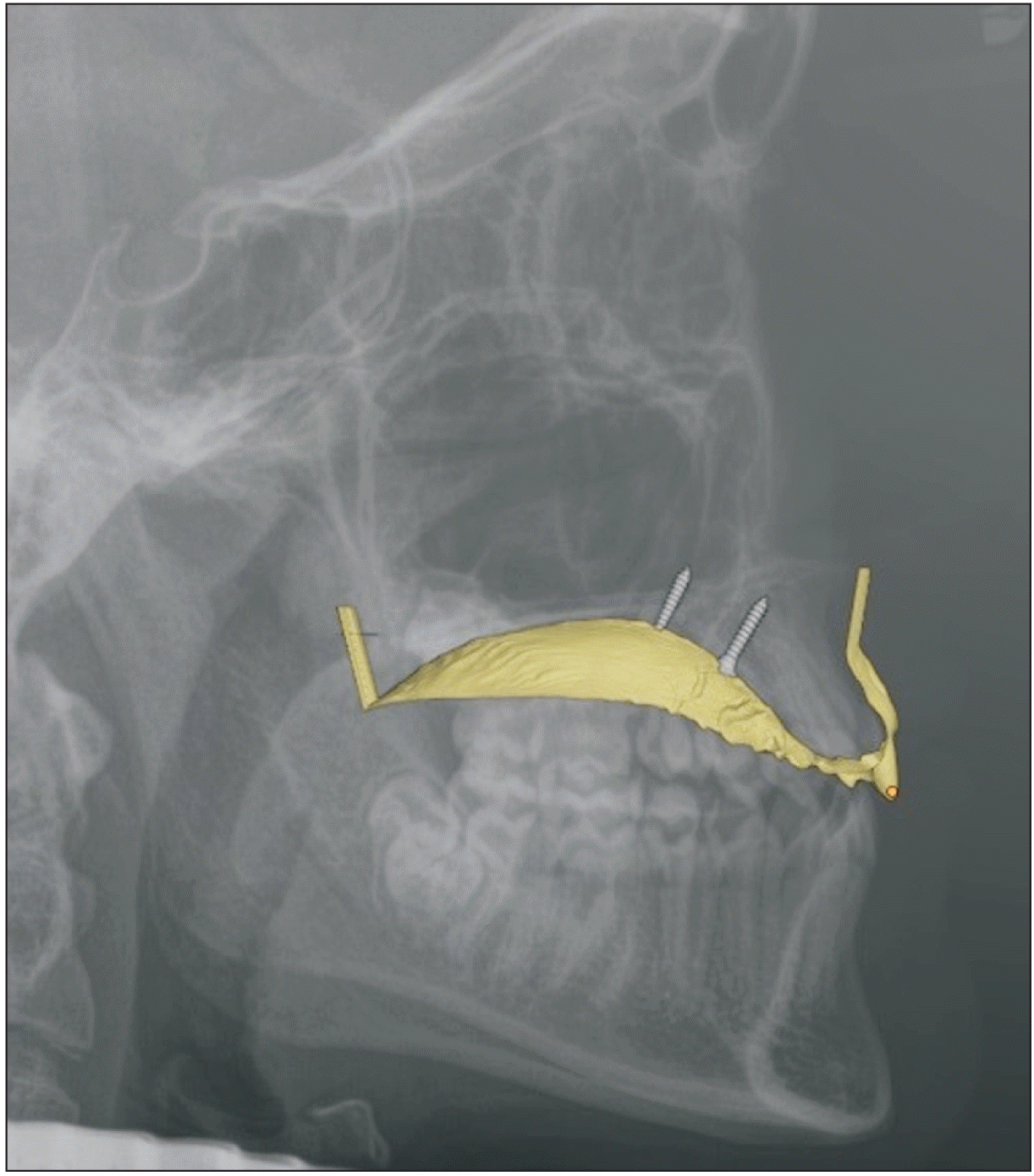
Figure 4
Insertion guide placed on the three-dimensional printed study model (left) and the diamond cylinder used to reduce resistance to sliding (right).
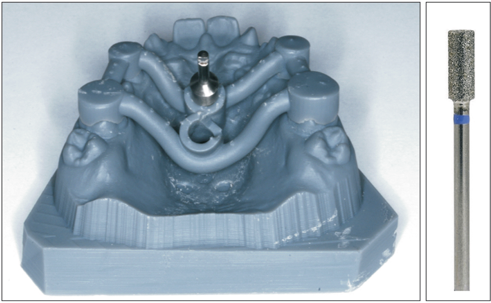
Figure 7
Finalized computer-aided design/computer-aided manufacturing fabricated Mesialslider on printed study model.
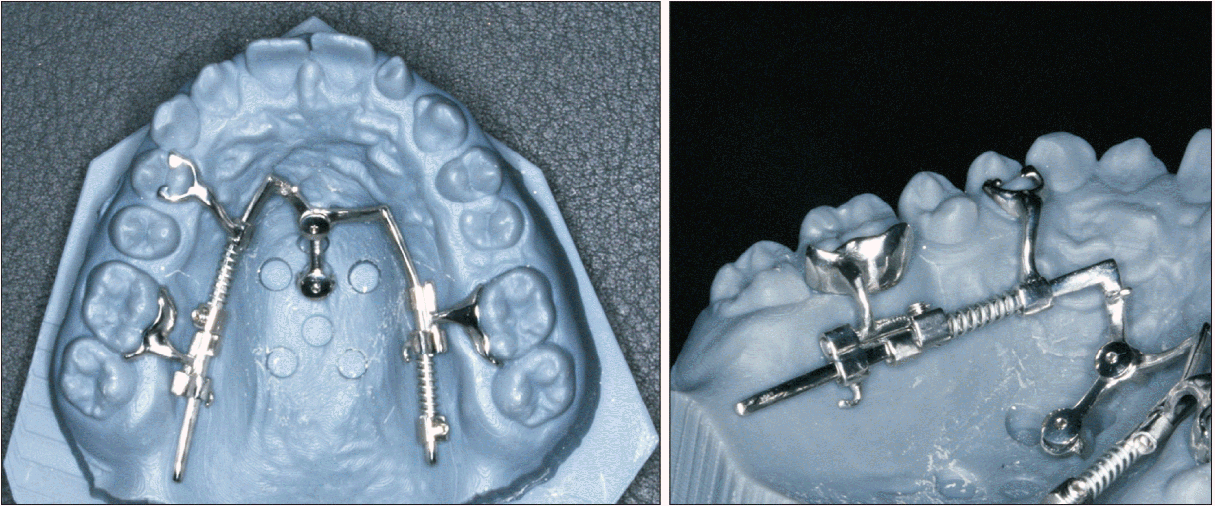
Figure 8
Insertion and activation of the Mesialslider right before extraction of the deciduous canine.
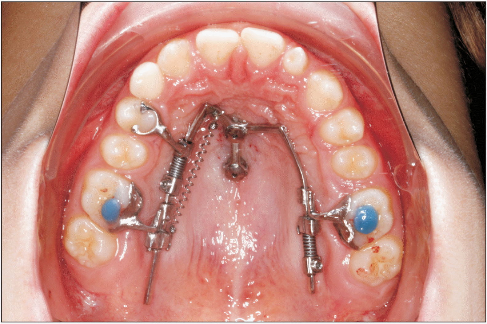
Figure 9
Intraoral photographs after 5 months of treatment. Spaces were almost closed in the anterior region.


 PDF
PDF Citation
 Print
Print



 XML Download