INTRODUCTION
MATERIALS AND METHODS
Study patients
Radiographic measurements
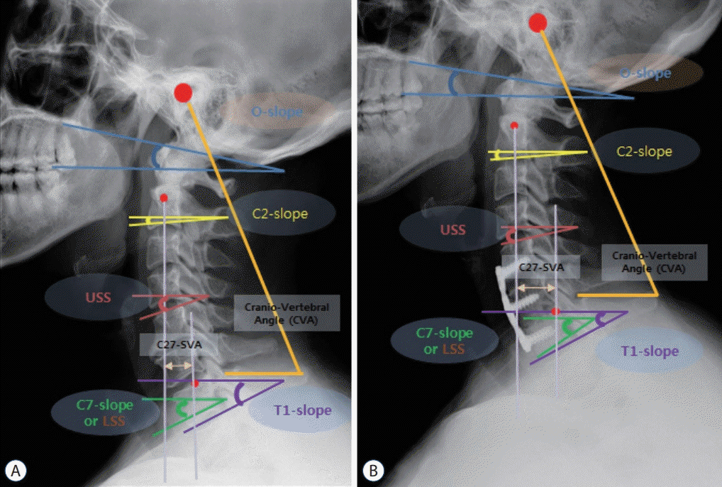
 | Fig. 1.Parameters measured before (A) and after surgery (B). The slope angle was measured with a horizontal line and a specific reference line at each cervical level : McGregor line (occipital slope), lower endplate of C2 body (C2 slope), lower endplate of C7 body (C7 slope), upper endplate of T1 body (T1 slope), upper segmental slope (USS), lower segmental slope (LSS). C2-7SVA (distance between the C2 plumb line and the superior posterior corner of C7 body), cranio-vertebral angle (CVA; the angle between the connecting line from the EAC to the distal tip of the spinous process of C7 and the horizontal line. |
Statistics
RESULTS
Whole patients
Table 1.
Sub-group analysis
Table 2.
Table 3.
Correlation analysis
Table 4.
| Os | C2s | C7s | T1s | T1s-CL | O-C2A | C2-7A | O-C7A | USS | LSS | SA | CVA | C2-7SVA | ||
|---|---|---|---|---|---|---|---|---|---|---|---|---|---|---|
| Pre-OP | ||||||||||||||
| C2s | 0.34* | 1 | 0.09 | 0.08 | -0.96* | -0.77* | 0.72* | 0.13 | 0.55* | 0.14 | 0.34* | 0.67* | -0.71* | |
| T1s-CL | -0.37* | -0.96* | 0.05 | -0.08 | 1 | 0.72* | -0.76* | -0.28* | -0.39* | 0.05 | -0.37* | -0.56* | 0.60* | |
| C2-7A | 0.20* | 0.72* | -0.61* | -0.58* | -0.76* | -0.57* | 1 | 0.63* | 0.13 | -0.55* | 0.71* | 0.24* | -0.31* | |
| T1S | 0.13 | 0.08 | 0.94* | 1 | -0.08 | 0.01 | -0.58* | -0.70* | 0.35* | 0.87* | -0.64* | 0.39* | -0.28* | |
| C7s | 0.07 | 0.09 | 1 | 0.94* | 0.05 | -0.04 | -0.61* | -0.76* | 0.31* | 0.90* | -0.66* | 0.39* | -0.33* | |
| Post-OP | ||||||||||||||
| C2s | 0.43* | 1 | 0.08 | 0.17 | -0.88* | -0.72* | 0.65* | 0.16 | 0.43* | 0.05 | 0.32* | 0.27* | -0.60* | |
| T1s-CL | -0.45* | -0.88* | 0.02 | -0.18 | 1 | 0.60* | -0.65* | -0.27* | -0.37* | 0.05 | -0.36* | -0.19 | 0.49* | |
| C2-7A | 0.18 | 0.65 * | -0.69 * | -0.56* | -0.65* | -0.54* | 1 | 0.73* | -0.02 | -0.65* | 0.74* | 0.12 | -0.16 | |
| T1S | 0.13 | 0.17 | 0.91* | 1 | -0.18 | -0.08 | -0.56* | -0.71* | 0.42* | 0.82* | -0.54* | 0.03 | -0.38* | |
| C7s | 0.14 | 0.08 | 1 | 0.91* | 0.02 | 0.01 | -0.69* | -0.81* | 0.43* | 0.91* | -0.67* | 0.09 | -0.36* | |
Os : occipital slope, C2s : C2 slope, C7s : C7 slope, T1s : T1 slope, T1s-CL : T1 slope minus cervical lordosis, O-C2A : O-C2 angle, C2-7A : C2-7 angle, O-C7A : O-C7 angle, USS : upper segmental slope, LSS : lower segmental slope, SA : segmental angle, CVA : cranio-vertebral angle, C2-7 SVA : C2-7 sagittal vertical axis, OP : operation
DISCUSSION
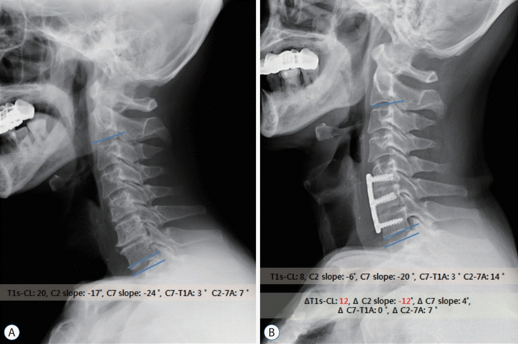
 | Fig. 2.Example of sagittal alignment changes after ACDF (A and B) in mismatch group patients (T1s-CL, 20). Two levels ACDF induced improvement of cervical lordosis (C2-7A) and T1s-CL (20→8). Because, C7-T1A remained constant with a small difference (3°), the difference value between T1s-CL and C2 slope was also maintained constantly. ACDF : anterior cervical discectomy and fusion, T1s-CL : T1 slope minus cervical lordosis, C2-7A : C2-7 angle, C7- T1A : C7-T1 angle. |
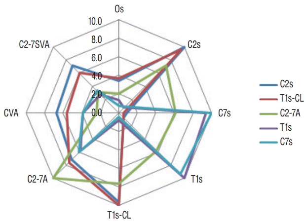
 | Fig. 3.This figure shows that the degree and trend of correlation among variable cervical radiologic parameters (occipital slope [Os], C2 slope [C2s], C7 slope [C7s], T1 slope [T1s], T1 slope minus cervical lordosis [T1s-CL], C2-7 angle [C2-7A], cranio-vertebral angle [CVA], C2-7 sagittal vertical axis [C2-7SVA]) in Table 4 (pre-operation). T1s-CL and C2s have very similar degrees and trends of correlation with other parameters and C7s and T1s also show very similar patterns of correlation. |


 PDF
PDF Citation
 Print
Print


 XML Download