INTRODUCTION
MATERIALS AND METHODS
Patient identification
Surgical procedures
PTCIF technique
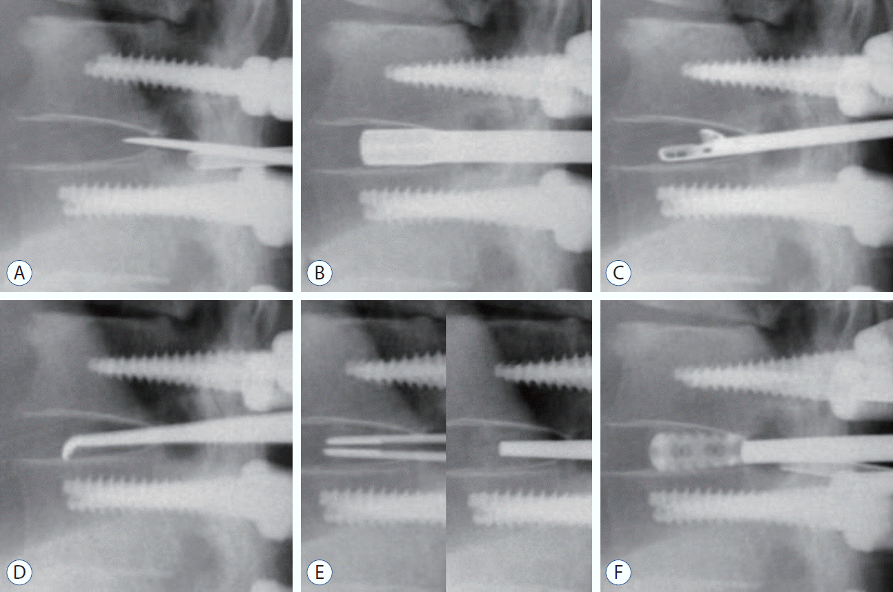 | Fig. 2.Intraoperative C-arm images in posterior thoracic cage interbody fusion procedures. A : Discectomy was performed after the incision of the annulus using knife and sharp osteotome. B : A shaver was inserted and rotated to scrub the endplate. C : The disc material was removed using a pituitary forcep. D : The remnant disc material of the endplate was curetted with an angled curette. E : Autologous bone chips were inserted into the disc space and packed by a sharp impactor to enhance bone fusion before cage insertion. F : Thereafter, cages packed with autologous bone chips were inserted. |
Conventional PLF technique
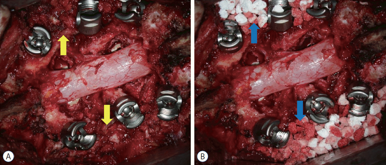 | Fig. 3.Images of conventional posterolateral fusion after posterior screw fixation and laminectomy images at surgical field are shown. Bone chips were applied onto the fusion bed obtained through extensive lateral muscle dissection. A : The yellow arrows indicate the local autologous bone chips. B : Allograft or hydroxyapatite bone chips can be used along with autologous bone chips. The blue arrows indicate the hydroxyapatite bone chips. |
Outcome evaluation
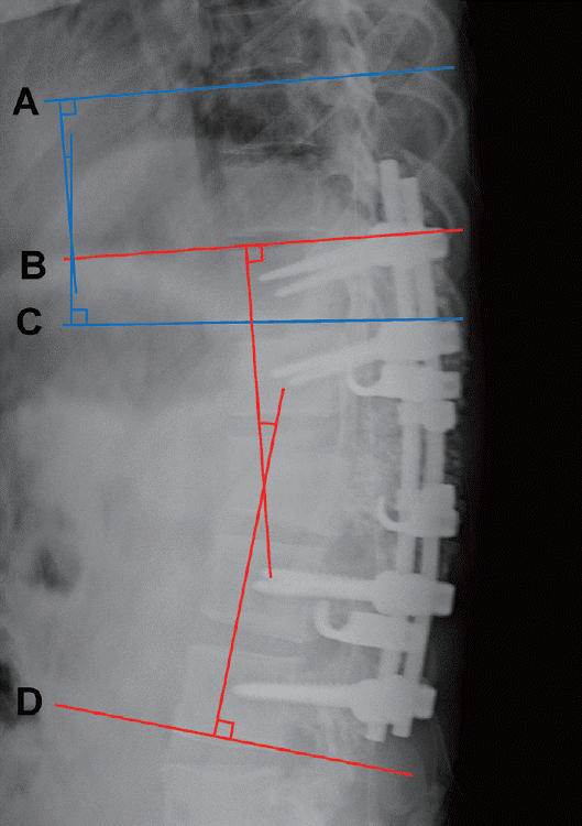 | Fig. 4.Radiological measurement of the sagittal X-ray. The regional Cobb angle is the angle between the red tangential line to the cephalad endplate line of the upper instrumented vertebrae (UIV) (B) and the red tangential line to the caudal endplate line of the lower instrumented vertebrae (D). The proximal junctional Cobb angle is the angle between the blue tangential line to the cephalad endplate line of the two supraadjacent vertebrae above the UIV (A) and the blue tangential line to the caudal endplate line of the UIV (C). |
Statistical analysis
RESULTS
Table 1.
Table 2.
Values are presented as mean±standard deviation or number (%). *The levels of interbody cage insertion with laminectomy as well as upper and lower levels, which were fixed by pedicle screws without laminectomy and bone chips were applied on the lamina, were all included. PTCIF : posterior thoracic cage interbody fusion, PLF : posterolateral fusion
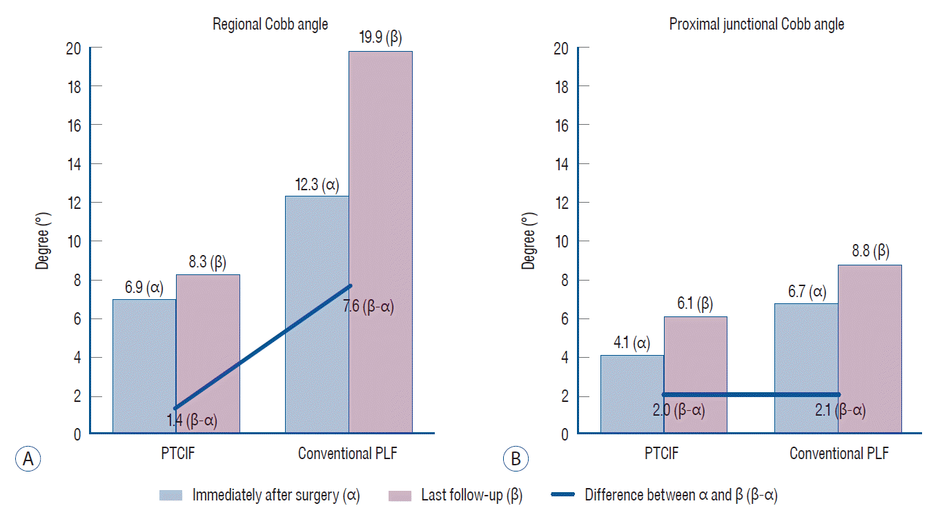 | Fig. 5.The changes of radiological parameters of the two groups during follow-up. A : The mean difference in the regional Cobb angle immediately after surgery compared with that of the last follow-up was 1.4° in posterior thoracic cage interbody fusion (PTCIF) and 7.6° in conventional posterolateral fusion (PLF), which showed significant difference between the two groups (p=0.003). B : The mean difference in the proximal junctional Cobb angle immediately after surgery compared with that of the last follow-up was 2.0° in PTCIF and 2.1° in conventional PLF, which showed no significant difference (p=0.97). |
Table 3.
Table 4.
| Value | |
|---|---|
| Levels of PTCIF only (n=30)* | |
| 1 level (19 cases, 63.3%) | |
| T10–11 | 6 (20.0) |
| T11–12 | 7 (23.3) |
| T12–L1 | 5 (16.7) |
| L1–2 | 1 (3.3) |
| 2 level (9 cases, 30.0%) | |
| T8–9–10 | 1 (3.3) |
| T10–11–12 | 4 (13.3) |
| T11–12–L1 | 2 (6.7) |
| T12–L1–2 | 1 (3.3) |
| L1–2–3 | 1 (3.3) |
| 3 level (2 cases, 6.7%) | |
| T12–L1–2–3 | 1 (3.3) |
| T10–11, L1–2–3 | 1 (3.3) |
| Lateralities of cage (n=43) | |
| Unilateral | 26 (60.5) |
| Bilateral | 17 (39.5) |
| Types of cage (n=43) | |
| 8 mm, 0° | 22 (51.1) |
| 8 mm, 4° | 11 (25.6) |
| 10 mm, 0° | 2 (4.7) |
| 10 mm, 4° | 1 (2.3) |
| 10 mm, 8° | 4 (9.3) |
| 12 mm, 4° | 1 (2.3) |
| 12 mm, 8° | 2 (4.7) |
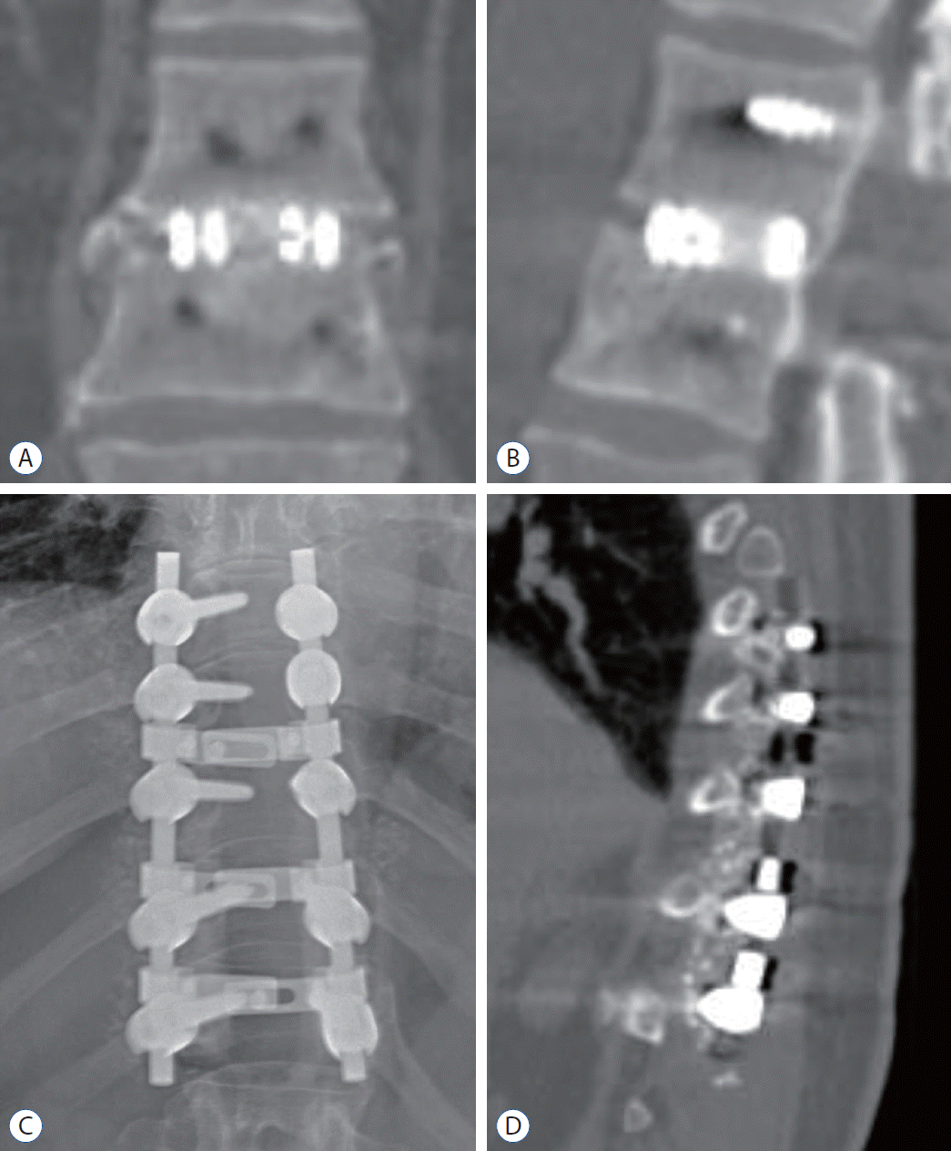 | Fig. 6.Bony continuity within and circumjacent the cages between the upper and lower endplates are well identified in coronal (A) and sagittal (B) CT images 3 months after PTCIF at T12–L1, whereas it is complex to verify the bony continuity in simple spine X-ray (C) and sagittal CT image (D) 3 months after conventional PLF. PTCIF : posterior thoracic cage interbody fusion, PLF : posterolateral fusion, CT : computed tomography. |


 PDF
PDF Citation
 Print
Print


 XML Download