Journal List > J Korean Neurosurg Soc > v.62(2) > 1160688

Lee, Jung, Kwak, Lee, Chung, Park, and Koh: Patient-Specific Computational Fluid Dynamics in Ruptured Posterior Communicating Aneurysms Using Measured Non-Newtonian Viscosity : A Preliminary Study

Abstract

Objective

The objective of this study was to analyze patient-specific blood flow in ruptured aneurysms using obtained non-Newtonian viscosity and to observe associated hemodynamic features and morphological effects.

Methods

Five patients with acute subarachnoid hemorrhage caused by ruptured posterior communicating artery aneurysms were included in the study. Patients’ blood samples were measured immediately after enrollment. Computational fluid dynamics (CFD) was conducted to evaluate viscosity distributions and wall shear stress (WSS) distributions using a patient-specific geometric model and shear-thinning viscosity properties.

Results

Substantial viscosity change was found at the dome of the aneurysms studied when applying non-Newtonian blood viscosity measured at peak-systole and end-diastole. The maximal WSS of the non-Newtonian model on an aneurysm at peaksystole was approximately 16% lower compared to Newtonian fluid, and most of the hemodynamic features of Newtonian flow at the aneurysms were higher, except for minimal WSS value. However, the differences between the Newtonian and non-Newtonian flow were not statistically significant. Rupture point of an aneurysm showed low WSS regardless of Newtonian or non-Newtonian CFD analyses.

Conclusion

By using measured non-Newtonian viscosity and geometry on patient-specific CFD analysis, morphologic differences in hemodynamic features, such as changes in whole blood viscosity and WSS, were observed. Therefore, measured non-Newtonian viscosity might be possibly useful to obtain patient-specific hemodynamic and morphologic result.

INTRODUCTION

After an intracranial aneurysm ruptures, a patient may experience various cerebrovascular complications due to abnormal site-specific hemodynamic responses [18]. Accurate information about hemodynamic changes present in a ruptured aneurysm can assist in planning the timing of surgical intervention and in predicting the prognosis of patients. The modifications in blood flow that result from aneurysm rupture have been rarely reported due to the limitation of obtaining high resolution in vivo measurements. Computational blood flow analysis has been used to overcome such technical limitations [12,20].
The flow in aneurysm models has been studied to assess risk and point of rupture [7,12,20,23]. However, relatively few studies have been conducted on blood f low in ruptured aneurysms, since blood behaves as a non-Newtonian fluid and the non-Newtonian rheological property of blood changes differently for each patient after hemorrhage [21,28,32].
In large arteries, the viscoelasticity of whole blood is not considered a predominant feature because shear rate in large arteries usually remains high [13]. It has thus been thought that whole blood can be considered to be a Newtonian fluid with a constant viscosity [25]. However, there is some debate about the viscosity property of whole blood in large arteries [8]. According to some sources, whole blood may be regarded as a non-Newtonian fluid in arteries at specific sites in which shear rate changes drastically, for example, flows around plaques, at bifurcations, and in aneurysms [29]. From a hemodynamic perspective, whole blood is characterized as a shear-thinning, non-Newtonian fluid in which viscosity decreases with increasing shear rate [13,29].
In order to apply non-Newtonian f low characteristics for numerical analysis, accurate viscosity information is required for the entire range of shear rates (i.e., from 0 to 1000 s-1) that changes abruptly at a specific site [26]. In particular, when a patient experiences hemorrhage, that patient will show symptom-dependent variations in viscosity characteristics [14,15,17]. Therefore, patient-specific non-Newtonian viscosity information can be used to accurately analyze site-specific f low behavior within a ruptured aneurysm instead of using Newtonian model and assumed non-Newtonian information.
The objective of the present study was to characterize blood flow in ruptured aneurysms of posterior communicating artery (Pcom) by characterizing patient-specific, shear-thinning viscosity properties of whole blood. We examined differences between Newtonian and non-Newtonian analyses as well as the hemodynamic parameters and morphological characteristics of ruptured aneurysms in clinically measured non-Newtonian flow to obtain more accurate analysis results.

MATERIALS AND METHODS

Patients

This study was approved by Institutional Review Board of Chonbuk National University Hospital, which waived informed consent. From January 2016 to August 2016, cerebral angiography was performed in 21 patients for evaluation of subarachnoid hemorrhage caused by aneurysmal rupture of Pcom.
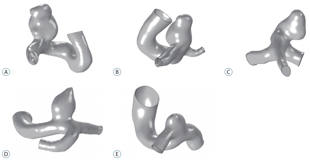
Inclusion criteria were as follows : 1) collection of venous study sampling obtained prior to saline infusion for viscosity measurement in our emergency room, 2) demonstration of a ruptured Pcom aneurysm on a source image from rotational cerebral angiography, and 3) an aneurysm size between 5 to 10 mm for optimal computational fluid dynamics (CFD). Of the 21 patients who underwent cerebral angiography, a total of 16 were excluded due to the receipt of a saline infusion before venous sampling at an outside hospital (n=10), small size aneurysms (n=2), giant ruptured aneurysms (n=3), or poor quality source imaging of rotational cerebral angiography (n=1). Our final study sample consisted of five patients with ruptured Pcom aneurysms with specific geometry. The morphology of these five ruptured aneurysms is shown in Fig. 1.

Image acquisition

Preoperative rotational cerebral angiography was performed with the use of a biplane angiography suite (Axiom Artis dBA; Siemens, Erlangen, German). A source image from rotational cerebral angiography for our study was obtained using the parameters : 1.5 degree rotation; at 29 frames/sec; total=8 seconds.

Geometric model construction

We used Materialise Mimics software (ver. 20.0; Materialise NV, Leuven, Belgium) to convert the source image of rotational cerebral angiography in DICOM format into a 3D solid model. During a reconstruction of the model, unrelated branches were removed from aneurysm models, except for branches closer to the ostium and aneurysm dome.
The height and width of the aneurysm and the diameter of the ostium were measured using the 3D model. Based on the measured values, aspect ratios were calculated by dividing the height of the aneurysm by the diameter of the ostium. The bottleneck ratios were calculated by dividing the width of the aneurysm by the diameter of the ostium. The surface area of the aneurysm and the cross-sectional area of the ostium were also calculated [20,23,39].

Determination of whole blood viscosity

Patient-specific, non-Newtonian viscosity of whole blood was measured within an hour after venous sampling with a scanning capillary tube viscometer (SCTV; BVD-Pro 1, Bio-Visco Inc., Jeonju, Korea) [21]. The five patient-specific blood viscosity profiles are clinically measured as shown in Fig. 2. The viscosity profiles were obtained in shear rate values ranging from 1 to 1000 s-1. To apply patient-specific, non-Newtonian flow behavior, two variables, yield stress and Casson constant, were determined based on the obtained viscosity profiles.

Numerical modeling

The prepared patient-specific 3D aneurysm models were imported into COMSOL Multiphysics Modeling software (version 5.2a; COMSOL Inc., Burlington, MA, USA) to generate meshes and to perform numerical modeling. The 3D blood flow domain was calculated using the continuity and Navier-Stokes equations [23]. The Casson fluid model, one of the widely used non-Newtonian constitutive equations, was used to determine viscosity change during cardiac cycles. Several studies have used the Casson f luid model to study pulsatile blood flow in aneurysm [1,6,25,31].
τ=τy+kγ˙ when τ>τyγ˙=0 when τ<τy
In the Casson model, indicates the wall shear stress (WSS) by blood flow, and represents the yield stress. Denotes a Casson constant, and is the shear rate [21]. The numerical model assumed incompressible blood flow and that the vessel wall was applied to be rigid with a no-slip condition because of a lack of information about the elasticity and thickness of the aneurysm [5,12]. Because this intracranial aneurysm model has a low Reynolds number, the laminar flow model was applied to the CFD analysis [34,40]. To compare f low characteristics between Newtonian and non-Newtonian conditions, the viscosity values at a shear rate of 300 s-1 from each patient’s viscosity profile were used for Newtonian flow analyses. Four cardiac cycles of 0.8 seconds were calculated, and because the first cycle was initially transient, data of the second cycle were collected for f low analyses. Pulsatile waveforms were taken from the whole arterial tree [4,25]. For inlet boundary condition, inlet area for each patient was used to calculate the average flow rate of 2.6 mL/s. For outlet boundary condition, zero pressure was applied due to lack of information on patient flow condition [20,25].

Hemodynamic analyses

Hemodynamic factors of the blood flow were obtained at peak-systole and end-diastole, respectively. Maximal and minimal WSS were the highest and lowest value during the second cardiac cycle, respectively. The mean WSS was calculated by averaging the WSS during the second cardiac cycle. The WSS at the parent artery was obtained at the volume except for the aneurysm dome and ostium. The WSS at aneurysm was calculated at the volume of aneurysm dome except for ostium and parent artery. The WSS at ostium was obtained by selecting the volume between the parent artery and aneurysm. To investigate WSS distribution of the rupture point of aneurysm, the daughter sac with the irregular geometric deformation was selected at the aneurysm dome.
The mean WSS at artery, aneurysm, and ostium for both Newtonian and non-Newtonian flow was calculated. The maximal and minimal WSS at aneurysm were also obtained. A Mann-Whitney rank sum test was employed to compare variations between Newtonian and non-Newtonian flow. The p-value 0.05 was considered statistically significant.

RESULTS

Viscosity distributions

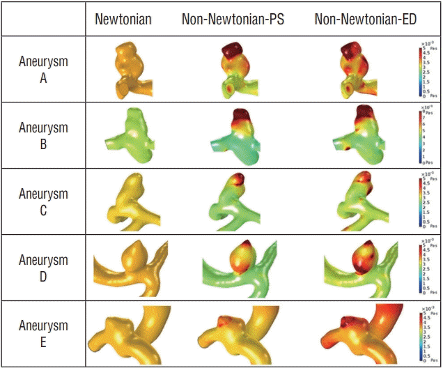
In Fig. 3, the patient-specific aneurysm models represent the difference between Newtonian and non-Newtonian viscosity distributions at peak-systole and end-diastole, respectively. As expected, in Fig. 3, a constant dynamic viscosity was distributed over the Newtonian aneurysm model, and no variation both at peak-systole and end-diastole was observed. In contrast, when considering the non-Newtonian flow condition, blood viscosity was unevenly distributed with different values according to specific locations, i.e., parent artery and aneurysm. A substantial difference in viscosity distribution was observed between peak-systole and end-diastole (Fig. 3).

Hemodynamic characteristics between Newtonian and non-Newtonian flow

Table 1 and Supplementary Tables 1 and 2 show hemodynamic variables for the aneurysms. The mean WSS at the ostium was higher than at the aneurysm. However, the average WSS at the artery was even higher than at the ostium using both the Newtonian model and non-Newtonian flow. When comparing WSS predicted by the two rheology models, the WSS obtained by Newtonian model was greater than that measured by non-Newtonian model regardless of locations and cardiac cycle. The average WSS at the artery with Newtonian flow (8.64±3.50 Pa) in peak systole was higher than with non-Newtonian flow (7.58±2.83 Pa). The mean WSS at aneurysm with Newtonian model (2.26±2.32 Pa) in peak-systole was 2.35 times greater than with non-Newtonian model (0.96±1.03 Pa). Average Newtonian WSS at the ostium was 21.01% higher than that of the non-Newtonian model in peak-systole. There was a 9.94% discrepancy of mean WSS between the two rheology models at the ostium with end-diastole. Maximal WSS of the aneurysm by the Newtonian rheology model at peak-systole was approximately 16% higher than that of the non-Newtonian model. In addition, the maximal WSS value on the aneurysm with non-Newtonian flow at end-diastole was 6.34% lower than with Newtonian flow. Most of the Newtonian hemodynamic characteristic measurements were higher than those of the non-Newtonian model, with the exception of the minimal WSS value at the aneurysm. The minimal value of the non-Newtonian WSS at the aneurysm was higher than the minimal value of the Newtonian flow. Although overall differences between Newtonian and non-Newtonian were observed, no statistical significance was found between two rheology models.

Flow characteristics at the tip of aneurysms

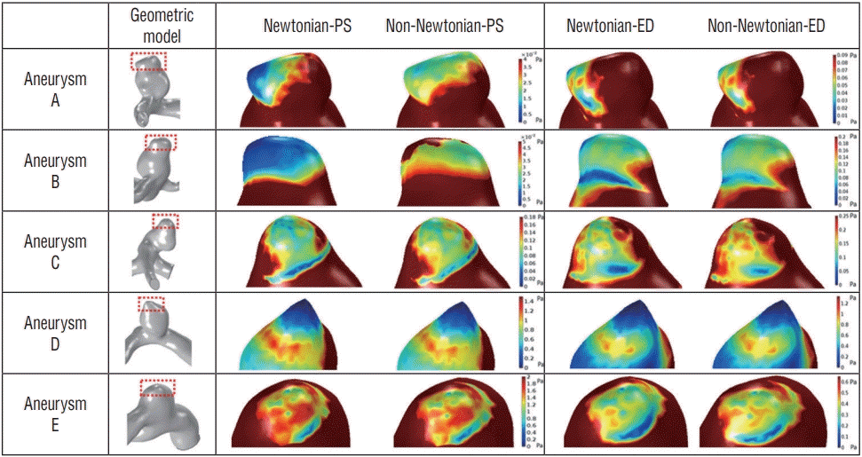
As shown in Table 1, the results of the minimal WSS at the aneurysm were particular, and the minimal point was located at the tip of the aneurysm in Fig. 4. Because a region of low WSS was found in the tip of the aneurysm and for more accurate analysis of WSS distributions, the range of WSS scale was adjusted more precisely. Fig. 4 provides distributions of WSS in the tip of the aneurysm where the rupture point exists. The aneurysm rupture point is marked with a red box, and the enlarged view of the rupture region is also included in Fig. 4. All aneurysm models clearly showed the difference between Newtonian and non-Newtonian WSS in both peak-systole and end-diastole at the rupture point.
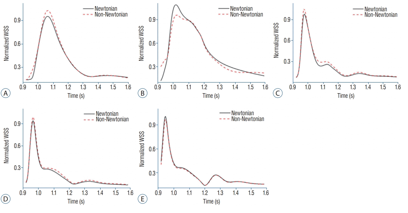
Fig. 5 shows changes of the normalized dimensionless WSS during the cardiac cycle at the rupture point of 5 aneurysms, A--E. As shown in Fig. 5, Newtonian WSS was lower when compared to non-Newtonian WSS at aneurysms A, C, and D. The differences between Newtonian and non-Newtonian normalized WSS for aneurysms A and C at peak-systole are shown in Fig. 5A and Fig. 5C. The normalized WSS of aneurysms A and C were 0.27 Pa and 1.15 Pa, respectively, in the Newtonian model and 0.29 Pa and 1.35 Pa, respectively, in the non-Newtonian model. However, as shown in Fig. 5D and Fig. 5E, normalized WSS between the two rheology models during the cardiac cycle showed little variation, and no statistical difference was observed (p=0.84 for aneurysm D, p =0.89 for aneurysm E). In aneurysm B (Fig. 5B), as opposed to other aneurysms, overestimated Newtonian WSS was observed in about 1.42 more times than in non-Newtonian WSS. In particular, aneurysm B showed a large increase in normalized WSS over the entire cardiac cycle, not just in a particular cardiac interval.

Morphological variables

Table 2 shows the morphologic variables of the five aneurysm models. Overall, aneurysms A, B, and C had larger morphological variable values than aneurysms D and E. Aneurysm A had the largest height (9.62 mm), width (8.54 mm) and area values while aneurysm E had the smallest height, width (2.85 mm and 5.03 mm) and area values. The largest ostium size was 7.25 mm (aneurysm A) and the smallest ostium size was 4.54 mm (aneurysm D). Aneurysm B had the largest ostium area, while aneurysm D had the smallest ostium area. Aneurysm D had the largest aspect ratio value (1.52) while aneurysm E had the smallest aspect ratio value (0.45). Both aneurysms C and D had the highest bottleneck ratio (1.24); the lowest bottleneck ratio was observed in aneurysm E (0.79).

DISCUSSION

Behavior of Newtonian and non-Newtonian whole blood viscosity

In Newtonian blood flow, linear relations between WSS and shear rate exist, and thus the value of blood viscosity is constant. In contrast, shear-thinning, non-Newtonian viscosity varies depending on shear rate. Therefore, a high whole blood viscosity value is observed at a low shear rate, whereas the viscosity of whole blood decreases with increasing shear rate [2,11,13].
Although some studies suggest that Newtonian rheology is simple to conduct using CFD studies, this method may not accurately present f low analysis of aneurysms (Fig. 3). As shown in the results of the viscosity distributions in our study, only the non-Newtonian model captures site-specific viscosity in the artery and aneurysms (Fig. 3).

Morphological effect of ruptured aneurysms and WSS

Previous studies have demonstrated that aneurysm rupture is associated with the change of WSS at the region of the tip or the entire dome of the aneurysm [20,32]. Morphologic and hemodynamic factors, such as WSS, are important to consider in evaluating the point of aneurysm rupture [12,24,37].
The non-Newtonian model determines site-specific viscosity, allowing changes of WSS in the rupture point to be analyzed more precisely. When aneurysm size is analyzed in each model, the area of two models (aneurysm D and E) are particularly smaller than the others (aneurysm A, B, and C) as shown in Table 2. These size differences show great discrepancies in Newtonian and non-Newtonian WSS analyses. The larger the size of the aneurysm area, the greater the shear rate changes between the ostium and the tip of the aneurysm. Therefore, the changes of WSS between the Newtonian and non-Newtonian analyses are larger because of the increased variation of the viscosity as shown in Fig. 3. On the contrary, small-sized aneurysms rarely demonstrate such a difference.
According to the non-Newtonian CFD analyses, as the size of aneurysm increased, the region of the lowered shear rate is widened (causing increasing non-Newtonian viscosity). In addition, WSS was also affected by the lowered shear rate area. Detailed size of each aneurysm model was shown in Table 2, and detailed hemodynamic factors of each aneurysm model were summarized in supplementary data.
Thus, the morphological factors of the aneurysm affect the change in hemodynamic components [20]. However, further studies are needed to validate other factors that may contribute to the evaluation of ruptured regions in aneurysms.

The importance of non-Newtonian CFD analysis to determine rupture point

The CFD analyses identify the rupture point at the lowest WSS region at the tip of the aneurysm [12,27]. Despite the support of CFD validation, some researchers have used CFD to identify rupture of aneurysms in the neck, where diagnosis is difficult [9,10]. In the present study, non-Newtonian blood viscosity sampled from actual patients was measured and applied to CFD models to determine rupture point. Although the rupture regions were slightly different among the models, all five models were ruptured at the tip of the aneurysm in the present study. Moreover, the low WSS region was widened, where the viscosity value was relatively high.
Newtonian and non-Newtonian rheological effect in CFD analysis of cerebral aneurysm is still controversial. In previous studies, blood was usually assumed as Newtonian f low for simple simulations [22,35]. Jou et el. [20] found that the hemodynamic results using Newtonian model might be different compared to realistic blood flow, but reasonable data was observed using Newtonian model. Valencia et al. [36] compared the hemodynamic factor using Newtonian model and non-Newtonian model, and similar results were found. So, they concluded that Newtonian model was reliable to use for blood flow simulation. In contrast, Rayz et al. [30] reported that non-Newtonian viscosity values showed different results in the low shear regions when compared with Newtonian model, and non-Newtonian model was suggested to be used particularly in the giant aneurysm. Solnordal et al. [33] showed that Newtonian model was inappropriate to analyze aneurysm dome where the low circulation zone exists, and overestimated WSS was observed using Newtonian model. In the present study, the results of WSS using Newtonian model were overestimated as shown in Table 1. In one of the references, a pulsatile CFD simulation of intracranial aneurysm hemodynamics was performed using a Newtonian viscosity model and two non-Newtonian models. As a result of Xiang et al.’s [38] analysis, the Newtonian model failed to capture the increasing viscosity in the low shear range and consequently, both shear rate and WSS were overestimated. Therefore, the previous study showed the difference between Newtonian and non-Newtonian model. However, the limitation of the study was that the analysis was performed using assumed non-Newtonian viscosity value without actually measuring the viscosity of the patients [25,38]. In contrast, our study actually measured patientspecific blood viscosity and performed both Newtonian and non-Newtonian analyses. As a result of the current analyses, we could confirm the difference between Newtonian and non-Newtonian flow. Table 1 shows that hemodynamic factors using Newtonian model were overestimated except minimal WSS at aneurysm. In addition, Fig. 5 shows the results of normalized WSS at the rupture site, and aneurysm A, C, and D models using Newtonian flow were underestimated among the five aneurysm models. These findings may be different from the previous studies [38].

The difficulty in conducting CFD study

The acquisition of patient-specific geometric models and non-Newtonian blood viscosity measurements are difficult to obtain. Therefore, in a number of prior studies, CFD analyses were conducted by using widely known Newtonian blood viscosity with constant values [3,16,19]. Large arteries, where the flow velocity is always high, have few differences between Newtonian and non-Newtonian CFD study measurements [13]. However, it is necessary to identify the site-specific risk by non-Newtonian CFD studies using a patient’s actual blood viscosity in the vicinity of the aneurysm and plaque where the flow velocity changes rapidly. In the present study, the patient-specific non-Newtonian blood viscosity values were applied to CFD studies. However, the range of the WSS distributions varied with larger magnitude using CFD studies when patient-specific non-Newtonian viscosity values were applied as shown in Fig. 2. In order to show the analysis results more effectively, the scale bar was applied differently for each aneurysm in Fig. 4. The results needed to be analyzed carefully because different scale bars have been applied to each model in practice, although the contours in the Fig. 4 showed no differences.

Limitations

The present study had several limitations. First, this study focused on ruptured aneurysms involving the posterior communicating artery. Because hemodynamic features (whole blood viscosity and WSS) are different for each location at similar anatomical vessels, studying other locations in which ruptured aneurysms may occur, such as the anterior communicating artery, middle cerebral artery, and pericallosal artery, is necessary. Second, because our five aneurysm models ranged in size, the hemodynamic results were varied. Moreover, the number of patients was too small to obtain statistically significant results. No significant difference between Newtonian flow and non-Newtonian flow was observed. Further study is needed to obtain statistically significant results using a larger number of aneurysms with similar sizes and to validate the present CFD study.

CONCLUSION

A patient-specific non-Newtonian model showed site-specific viscosity results in arteries and aneurysms compared to Newtonian flow. Morphologic factors of aneurysms affected the changes of non-Newtonian WSS. CFD analysis was used to determine the rupture point, and as a result, hemodynamic parameters using the Newtonian model were mostly higher as compared to those using non-Newtonian blood flow except for minimal wall WSS at aneurysm. CFD analysis using measured non-Newtonian viscosity might be used to obtain more precise patient-specific hemodynamic and morphologic results.

Notes

No potential conflict of interest relevant to this article was reported.

INFORMED CONSENT

Informed consent was obtained from all individual participants included in this study.

ACKNOWLEDGMENTS

This research was supported by Basic Science Research Program (NRF-2016R1D1A3B03935132 and NRF-2017R1A4A1015681) by the National Research Foundation of Korea (NRF) funded by the Ministry of Education.

Supplementary Materials

The online-only data supplement is available with this article at https://doi.org/10.3340/jkns.2017.0314.

References

1. Aroesty J, Gross JF. The mathematics of pulsatile flow in small vessels. I. Casson theory. Microvasc Res. 4:1–12. 1972.
crossref
2. Baskurt OK, Meiselman HJ. Blood rheology and hemodynamics. Semin Thromb Hemost. 29:435–450. 2003.
crossref
3. Castro MA, Putman CM, Sheridan MJ, Cebral JR. Hemodynamic patterns of anterior communicating artery aneurysms: a possible association with rupture. AJNR Am J Neuroradiol. 30:297–302. 2009.
crossref
4. Cebral JR, Castro MA, Appanaboyina S, Putman CM, Millan D, Frangi AF. Efficient pipeline for image-based patient-specific analysis of cerebral aneurysm hemodynamics: technique and sensitivity. IEEE Trans Med Imaging. 24:457–467. 2005.
crossref
5. Cebral JR, Castro MA, Burgess JE, Pergolizzi RS, Sheridan MJ, Putman CM. Characterization of cerebral aneurysms for assessing risk of rupture by using patient-specific computational hemodynamics models. AJNR Am J Neuroradiol. 26:2550–2559. 2005.
6. Chaturani P, Samy RP. Pulsatile flow of Casson’s fluid through stenosed arteries with applications to blood flow. Biorheology. 23:499–511. 1986.
crossref
7. Chien A, Castro M, Tateshima S, Sayre J, Cebral J, Viñuela F. Quantitative hemodynamic analysis of brain aneurysms at different locations. AJNR Am J Neuroradiol. 30:1507–1512. 2009.
crossref
8. Cho YI, Kensey KR. Effects of the non-Newtonian viscosity of blood on flows in a diseased arterial vessel. Part 1: steady flows. Biorheology. 28:241–262. 1991.
crossref
9. Crawford T. Some observations on the pathogenesis and natural history of intracranial aneurysms. J Neurol Neurosurg Psychiatry. 22:259–266. 1959.
crossref
10. Crompton MR. Mechanism of growth and rupture in cerebral berry aneurysms. Br Med J. 1:1138–1142. 1966.
crossref
11. Errill EW. Rheology of blood. Physiol Rev. 49:863–888. 1969.
crossref
12. Fukazawa K, Ishida F, Umeda Y, Miura Y, Shimosaka S, Matsushima S, et al. Using computational fluid dynamics analysis to characterize local hemodynamic features of middle cerebral artery aneurysm rupture points. World Neurosurg. 83:80–86. 2015.
crossref
13. Gijsen FJ, van de Vosse FN, Janssen JD. The influence of the non-Newtonian properties of blood on the flow in large arteries: steady flow in a carotid bifurcation model. J Biomech. 32:601–608. 1999.
crossref
14. Hilzenrat N, Arish A, Yaari A, Almog Y, Sikuler E. Blood viscosity, hemodynamics and vascular hindrance in a rat model of acute controlled bleeding and volume restitution with blood or Haemaccel. Acta Anaesthesiol Scand. 45:371–376. 2001.
crossref
15. Hilzenrat N, Arish A, Yaari A, Sikuler E. Acute hemodynamic changes following hemorrhage and volume restitution, using a low viscosity plasma expander, in anesthetized portal hypertensive rats. J Hepatol. 31:874–879. 1999.
crossref
16. Hodis S, Uthamaraj S, Lanzino G, Kallmes DF, Dragomir-Daescu D. Computational fluid dynamics simulation of an anterior communicating artery ruptured during angiography. J Neurointerv Surg. 6:e14. 2014.
crossref
17. Hopkins RW, Fratianne RB, Rao KV, Damewood CA. Effects of hematocrit and viscosity on continuing hemorrhage. J Trauma. 14:482–493. 1974.
crossref
18. Ishii R. Regional cerebral blood flow in patients with ruptured intracranial aneurysms. J Neurosurg. 50:587–594. 1979.
crossref
19. Jansen I, Schneiders J, Potters W, van Ooij P, van den Berg R, van Bavel E, et al. Generalized versus patient-specific inflow boundary conditions in computational fluid dynamics simulations of cerebral aneurysmal hemodynamics. AJNR Am J Neuroradiol. 35:1543–1548. 2014.
crossref
20. Jou LD, Lee DH, Morsi H, Mawad ME. Wall shear stress on ruptured and unruptured intracranial aneurysms at the internal carotid artery. AJNR Am J Neuroradiol. 29:1761–1767. 2008.
crossref
21. Jung JM, Lee DH, Kim KT, Choi MS, Cho YG, Lee HS, et al. Reference intervals for whole blood viscosity using the analytical performance-evaluated scanning capillary tube viscometer. Clin Biochem. 47:489–493. 2014.
crossref
22. Karmonik C, Zhang YJ, Diaz O, Klucznik R, Partovi S, Grossman RG, et al. Magnetic resonance imaging as a tool to assess reliability in simulating hemodynamics in cerebral aneurysms with a dedicated computational fluid dynamics prototype: preliminary results. Cardiovasc Diagn Ther. 4:207–212. 2014.
23. Le WJ, Zhu YQ, Li MH, Yan L, Tan HQ, Xiao SM, et al. New method for retrospective study of hemodynamic changes before and after aneurysm formation in patients with ruptured or unruptured aneurysms. BMC Neurol. 13:166. 2013.
crossref
24. Meng H, Wang Z, Hoi Y, Gao L, Metaxa E, Swartz DD, et al. Complex hemodynamics at the apex of an arterial bifurcation induces vascular remodeling resembling cerebral aneurysm initiation. Stroke. 38:1924–1931. 2007.
crossref
25. Morales HG, Larrabide I, Geers AJ, Aguilar ML, Frangi AF. Newtonian and non-Newtonian blood flow in coiled cerebral aneurysms. J Biomech. 46:2158–2164. 2013.
crossref
26. Nicodemo L, Nicolais L, Landel RF. Shear rate dependent viscosity of suspensions in Newtonian and non-Newtonian liquids. Chem Eng Sci. 29:729–735. 1974.
crossref
27. Nixon AM, Gunel M, Sumpio BE. The critical role of hemodynamics in the development of cerebral vascular disease: a review. J Neurosurg. 112:1240–1253. 2010.
crossref
28. Ohkuma H, Manabe H, Tanaka M, Suzuki S. Impact of cerebral microcirculatory changes on cerebral blood flow during cerebral vasospasm after aneurysmal subarachnoid hemorrhage. Stroke. 31:1621–1627. 2000.
crossref
29. Perktold K, Peter R, Resch M. Pulsatile non-Newtonian blood flow simulation through a bifurcation with an aneurysm. Biorheology. 26:1011–1030. 1989.
crossref
30. Rayz VL, Boussel L, Lawton MT, Acevedo-Bolton G, Ge L, Young WL, et al. Numerical modeling of the flow in intracranial aneurysms: prediction of regions prone to thrombus formation. Ann Biomed Eng. 36:1793–1804. 2008.
crossref
31. Sankar D, Hemalatha K. A non-Newtonian fluid flow model for blood flow through a catheterized artery—steady flow. Appl Math Model. 31:1847–1864. 2007.
crossref
32. Shojima M, Oshima M, Takagi K, Torii R, Hayakawa M, Katada K, et al. Magnitude and role of wall shear stress on cerebral aneurysm: computational fluid dynamic study of 20 middle cerebral artery aneurysms. Stroke. 35:2500–2505. 2004.
crossref
33. Solnordal CB, Liovic P, Delaney GW, Cummins SJ, Schwarz MP, Witt PJ, editors. CFD sensitivity study for Newtonian viscosity model in cerebral aneurysms. Eleventh international conference on computational fluid dynamics in the minerals and process industries. 2015 Dec 7-9; Melbourne, Australia. Melbourne: CSIRO; 2015 Dec.
34. Takao H, Murayama Y, Otsuka S, Qian Y, Mohamed A, Masuda S, et al. Hemodynamic differences between unruptured and ruptured intracranial aneurysms during observation. Stroke. 43:1436–1439. 2012.
crossref
35. Valen-Sendstad K, Steinman DA. Mind the gap: impact of computational fluid dynamics solution strategy on prediction of intracranial aneurysm hemodynamics and rupture status indicators. AJNR Am J Neuroradiol. 35:536–543. 2014.
crossref
36. Valencia A, Zarate A, Galvez M, Badilla L. Non‐Newtonian blood flow dynamics in a right internal carotid artery with a saccular aneurysm. Int J Numer Methods Fluids. 50:751–764. 2006.
crossref
37. Xiang J, Natarajan SK, Tremmel M, Ma D, Mocco J, Hopkins LN, et al. Hemodynamic-morphologic discriminants for intracranial aneurysm rupture. Stroke. 42:144–152. 2011.
crossref
38. Xiang J, Tremmel M, Kolega J, Levy EI, Natarajan SK, Meng H. Newtonian viscosity model could overestimate wall shear stress in intracranial aneurysm domes and underestimate rupture risk. J Neurointerv Surg. 4:351–357. 2012.
crossref
39. Zeng Z, Kallmes DF, Durka M, Ding Y, Lewis D, Kadirvel R, et al. Hemodynamics and anatomy of elastase-induced rabbit aneurysm models: similarity to human cerebral aneurysms? AJNR Am J Neuroradiol. 32:595–601. 2011.
crossref
40. Zhang Y, Jing L, Zhang Y, Liu J, Yang X. Low wall shear stress is associated with the rupture of intracranial aneurysm with known rupture point: case report and literature review. BMC Neurol. 16:231. 2016.
crossref

Fig. 1.
A-E : Patient-specific geometric models of ruptured aneurysms.
jkns-2017-0314f1.tif
Fig. 2.
Clinically measured blood viscosity profiles.
jkns-2017-0314f2.tif
Fig. 3.
Whole blood viscosity (WBV) distributions of aneurysms. Whole blood viscosity with Newtonian viscosity at both peak-systole and enddiastole is shown in Newtonian column. Non-Newtonian WBV at peaksystole and WBV using non-Newtonian rheology model at end-diastole are shown according to each aneurysm model. PS : peak-systole, ED :end-diastole.
jkns-2017-0314f3.tif
Fig. 4.
Comparison of the simulation results between Newtonian and nonNewtonian wall shear stress during cardiac cycle at rupture point of aneur ysms. Dif ferent scale bar is applied to each model. The aneurysm rupture point is marked with a red box, and the enlarged view of the ruptured region is also included. PS : peak-systole, ED : end-diastole.
jkns-2017-0314f4.tif
Fig. 5.
A-E : Normalized mean wall sheer stress (WSS) versus the time. Volume average of Newtonian and non-Newtonian WSS at rupture point of aneurysms. Newtonian was underestimated in most aneurysm results except for aneurysm B and E. See the text for a detailed description.
jkns-2017-0314f5.tif
Table 1.
Hemodynamic characteristics between Newtonian and non-Newtonian flow
PS (n=5)
p-value ED (n=5)
p-value
Newtonian flow Non-Newtonian flow Newtonian flow Non-Newtonian flow
Mean WSS at artery (Pa) 8.64±3.50 7.58±2.83 0.54 1.76±0.69 1.65±0.56 0.54
Mean WSS at aneurysm (Pa) 2.26±2.32 0.96±1.03 0.42 0.78±0.53 0.50±0.24 0.54
Mean WSS at ostium (Pa) 8.12±3.40 6.71±2.73 0.42 2.10±0.78 1.91±0.69 0.69
Maximal WSS at aneurysm (Pa) 26.39±10.04 22.76±7.88 0.31 6.87±2.61 6.46±2.19 0.84
Minimal WSS at aneurysm (Pa) 0.05±0.1 0.07±0.11 0.09 0.01±0.02 0.033±0.02 0.22

The detail of the results is included in Supplementary Tables 1 and 2.

PS : peak-systole, ED : end-diastole, WSS : wall shear stress, Pa : unit of wall shear stress

Table 2.
Morphological variables for the aneurysms
Aneurysm A Aneurysm B Aneurysm C Aneurysm D Aneurysm E
Height size (mm) 9.62 7.72 6.54 6.93 2.85
Width size (mm) 8.54 7.49 7.36 5.64 5.03
Ostium size (mm) 7.25 6.97 5.89 4.54 6.29
Aspect ratio 1.32 1.10 1.11 1.52 0.45
Bottleneck ratio 1.17 1.07 1.24 1.24 0.79
Area at aneurysm (mm2) 271.00 185.40 146.00 97.16 70.34
Ostium area (mm2) 30.67 36.01 19.90 11.84 19.38
TOOLS
Similar articles