Case 1
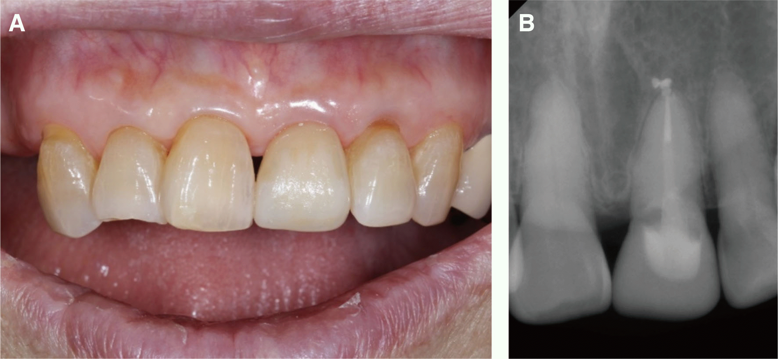
A 35-year-old man presented to the dental hospital with intermittent gingival pain in the region of the maxillary right central incisor. The tooth had undergone root canal treatment 8 - 9 years ago, followed by a ceramic crown restoration (
Fig. 1A). On clinical examination, the teeth were tender to percussion, with tenderness on palpation of the buccal gingiva. Radiographic examination revealed periapical radiolucency of the maxillary right central incisor and an ill-fitting margin of the restoration (
Fig. 1B). A diagnosis of symptomatic apical periodontitis with recurrent cervical caries was made. A non-surgical root canal retreatment and placement of a new CAD/CAM restoration were planned. Preliminary scan of the old restoration was performed with an intraoral scanner (CEREC AC omnicam; Dentsply Sirona, Charlotte, USA) to copy the old restoration before removal of the old crown (
Fig. 1C, 1D).
 | Fig. 1Preoperative images. (A) Intraoral clinical photo and (B) Periapical radiograph. Note the periapical radiolucency on the apex of the maxillary right central incisor. (C) and (D) Occlusal and labial views of intraoral 3-dimensional scan images before removing the old restoration. 
|
The neighboring teeth, maxillary left central and lateral incisors were previously restored with porcelain-fused-to-metal crowns, and the restorations showed a grayish hue along the gingival margin of the restorations. Replacement of both the maxillary central incisor restoration and left lateral incisor restoration was recommended to the patient for esthetic purposes, but he declined the replacement of the maxillary left central and lateral incisor restorations. Thus, the replacement of only the maxillary right central incisor restoration was planned. Lithium disilicate (LS2) block (IPS e.max CAD; Ivoclar Vivadent, Schaan, Liechtenstein) was selected because of its high mechanical properties,
11 but its monochromatic shade would have impeded the ability of the restoration to mimic the natural shade of the adjacent teeth.
Therefore, to mimic the natural shade, a preliminary experiment was performed on an A2 low translucent (LT) LS2 block. Four 3-mm thick specimens were fabricated using a high-speed diamond saw (Isomet 5000; Buehler, Lake Bluff, USA). Shade customization, using glaze paste and staining kit (IPS e.max CAD Crystall/Shades, Stains, Glaze and Glaze Liquid; Ivoclar Vivadent), and surface characterization were performed on the block as follows (
Fig. 2):
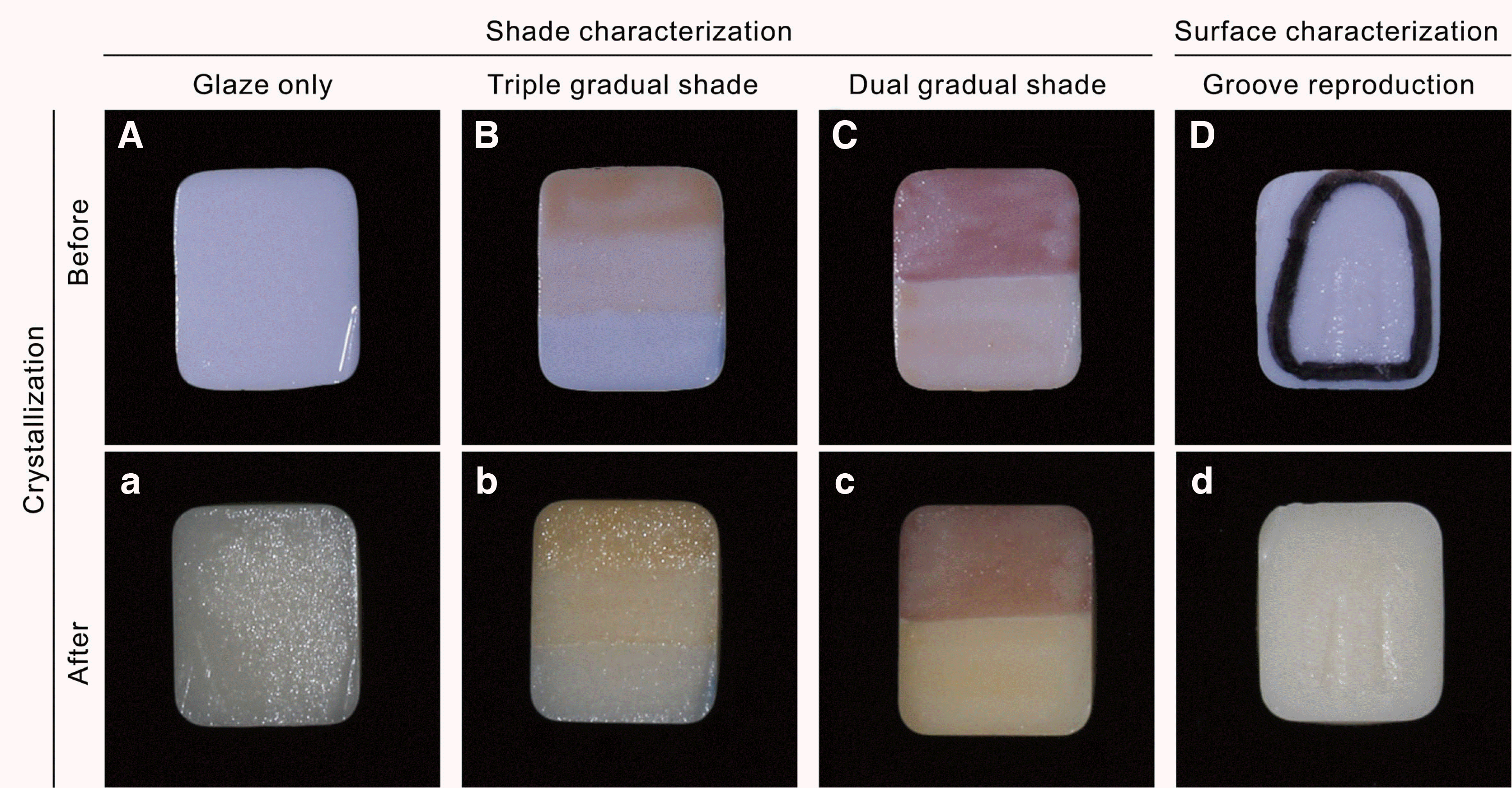 | Fig. 2Experimental shade and surface characterization on lithium disilicate (LS2) blocks. (A) Glaze only; application of an even layer of glaze paste, (a) after crystallization. (B) Three-tone gradual shade; application of double and single coat of shade 1 in the cervical and middle third, respectively. Application of one coat of blue incisal shade in the incisal third, (b) after crystallization. (C) Two-tone gradual shade; application of one coat of mahogany stain on the upper half, and one coat of copper stain on the lower half of the A2 lithium disilicate block, (c) after crystallization. (D) Surface characterization; surface roughening of the restoration using diamond point (F102R; Shofu, Kyoto, Japan) to reproduce the developmental grooves, (d) after crystallization. 
|
Color of the 4 specimens, before and after crystallization, was assessed by the CIE L*a*b* values obtained using a spectrophotometer (NF999; NIPPON DENSHOKU, Tokyo, Japan). The average CIE L*a*b* value obtained was compared with that of the Vitapan classical shade guide (Vita Zahnfabrik, Bad Säckingen, Germany).
In the following equation, E represents the CIE
L*
a*
b* color value of the experimental block, and V represents that of the Vitapan shade guide tap.
10
The results are shown in
Tables 1 and 2. Briefly, the color value of 1 coat of shade 1 on the A2 LT LS2 block was most similar to that of the Vita A3 shade (∆E = 1.62), whereas 2 coats of shade 1 on the block were most similar to the Vita A3.5 shade (∆E = 2.44).
12 In this experiment, the specimen that underwent surface characterization showed increased L* value as compared to the specimen that was only glazed. Copper and mahogany-colored staining caused severe discrepancy in values. In this case, surface characterization, for reproducing the microanatomy and application of shade 1 and for shade-matching of the restoration, was adopted according to the experimental results.
Table 1
Lab values of surface characterized lithium disilicate A2 blocks and Vita Shade guide
|
|
Vitapan Classical Shade guide (Control) |
|
Lithium disilicate A2 blocks (Experimental) (n = 3) |
|
|
Shade A2 |
|
|
Shade A3 |
Shade A3.5 |
Shade A2 |
Shade characterization |
Surface characterization |
|
|
Glaze |
1 coat of shade 1 |
2 coats of shade 1 |
Copper stain |
Mahogany stain |
Groove reproduction |
|
L |
57.71 |
53.72 |
50.49 |
56.83 |
55.02 |
52.73 |
55.4 |
44.29 |
57.9 |
|
a |
-0.21 |
0.12 |
0.8 |
-0.97 |
-0.78 |
1.76 |
0.03 |
6.02 |
-0.73 |
|
b |
5.59 |
7.79 |
9.99 |
3.49 |
8.18 |
9.93 |
10.82 |
8.61 |
3.5 |

Non-surgical root canal retreatment was performed on the maxillary right central incisor (
Fig. 3A, 3B) and followed with fiber post cementation (DT Light-Post; Bisco, Schaumburg, USA) and resin core restoration (Z100; 3M ESPE, St. Paul, USA). After crown preparation, an intraoral scan was performed and a conventional final impression of the maxillary right central incisor, using polyvinyl siloxane (Imprint 4; 3M ESPE), was taken. The cast model was fabricated from the conventional impression for experimental purpose. The shade of the maxillary right lateral incisor was recorded using a digital shade-matching device (Vita Easyshade V; VITA Zahnfabrik), as a reference for the shade determination of the LS2 crown. Under the “measurement on tooth area” mode, the shades in the incisal, middle, and cervical thirds of the maxillary right lateral incisor were recorded. The shade in the cervical third was recorded as A3.5, middle third as A3, and incisal third as A2 with translucency. Thereafter, a provisional crown was fabricated for the maxillary right central incisor.
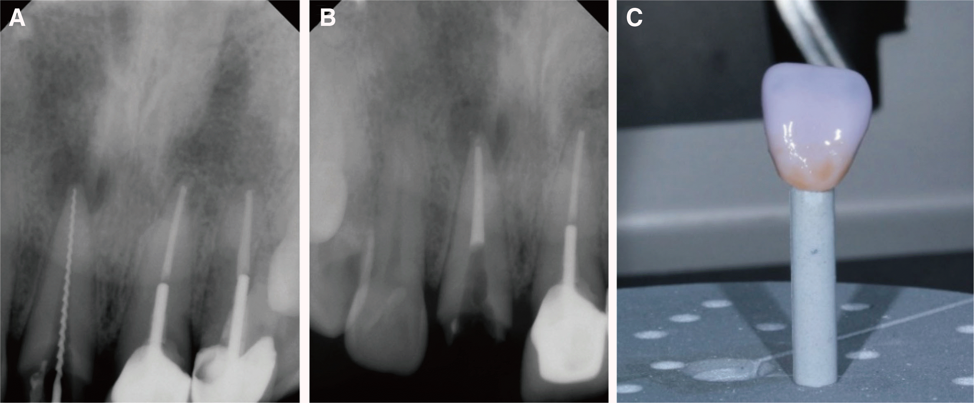 | Fig. 3(A) Periapical radiographies of working length determination, (B) Periapical radiographies of the endodontic canal filling, (C) Photography of staining of the lithium disilicate crown. 
|
The new crown was fabricated with the CAD/CAM system (CEREC MC X; Dentsply Sirona), using the A2 LT LS2 block. According to the results obtained from the previous experiment, surface characterization was imparted to the middle third of the labial surface of the restoration, using a diamond point bur (F102R; Shofu, Kyoto, Japan). In the cervical third of the restoration, 2 coats of shade 1 were applied to reproduce the A3.5 shade. In the middle third of it, 1 coat of shade 1 was applied to reproduce the A3 shade. In the incisal third of it, a blue shade was applied for reproducing incisal translucency (
Fig. 3C). Thereafter, crystallization was performed in a ceramic furnace (Programat P310; Ivoclar Vivadent), and the crown was allowed to cool for 10 min. Further, 9.5% hydrofluoric acid (Porcelain etchant; Bisco) was applied to the internal surface of the restoration for 20 s; the surface was then washed with air-water spray and dried. Thereafter, a silane coupling agent (Monobond-S; Ivoclar Vivadent) was applied for 60 s, after which the surface was thoroughly air-dried. 37% phosphoric acid (ETCH-37
TM; BISCO) was applied to prepared tooth surface for 20 s; the surface was then rinsed for 20 s and air-dried. Thereafter, dentin adhesive (All-Bond Universal; Bisco) was applied to the tooth surface according to the manufacturer’s instructions. Dual-cure resin cement (Duo-Link; Bisco) was mixed in a spiral syringe and applied to the internal surface of the crown, and it was seated on the prepared tooth. Initial light curing was performed for 5 s, and the excess cement was removed with a dental explorer. The resin cement was polymerized from each margin using visible light with an irradiance of 1200 mW/cm
2 (Bluephase G2; Ivoclar Vivadent) (
Fig. 4A, 4B). The occlusion was checked and adjusted after the crown was cemented.
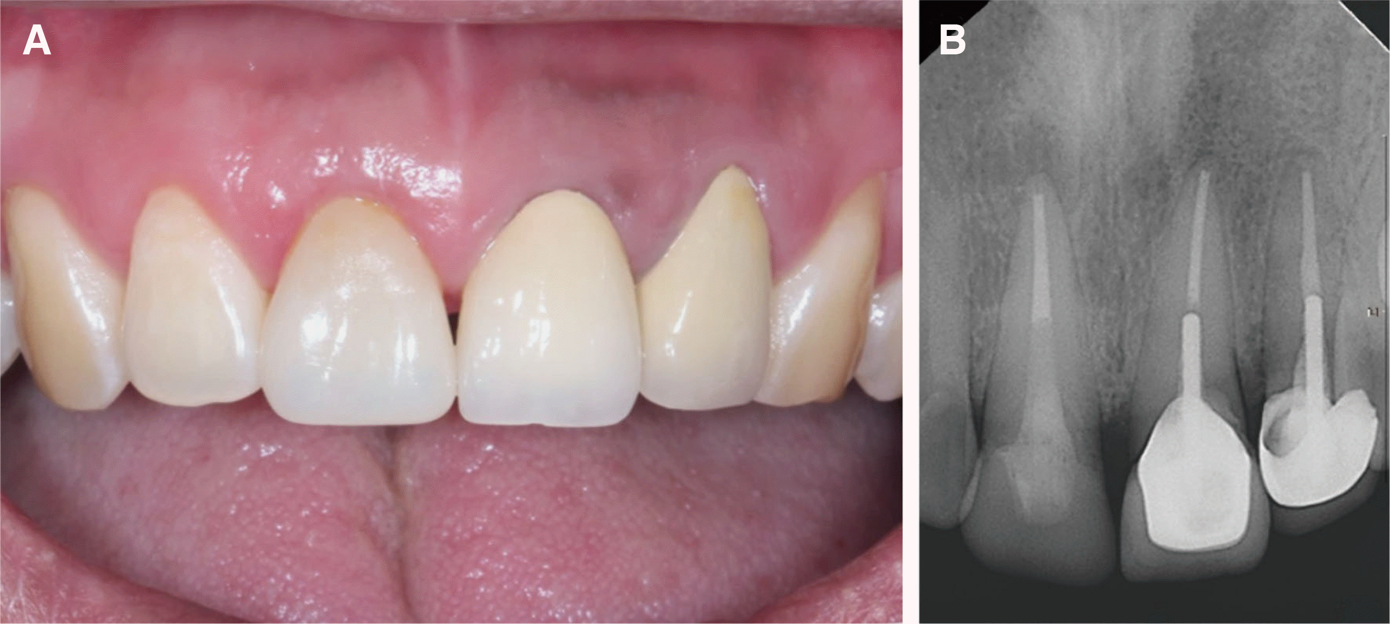 | Fig. 4(A) Intraoral photo and (B) Periapical radiograph after final cementation. 
|
Case 2
An 81-year-old woman presented at the dental clinic with a fractured maxillary left central incisor. Clinical and radiological examinations revealed a complicated crown fracture of the maxillary left central incisor (
Fig. 5A, 5B). A non-surgical root canal treatment followed by a CAD/CAM crown restoration in a single visit were planned.
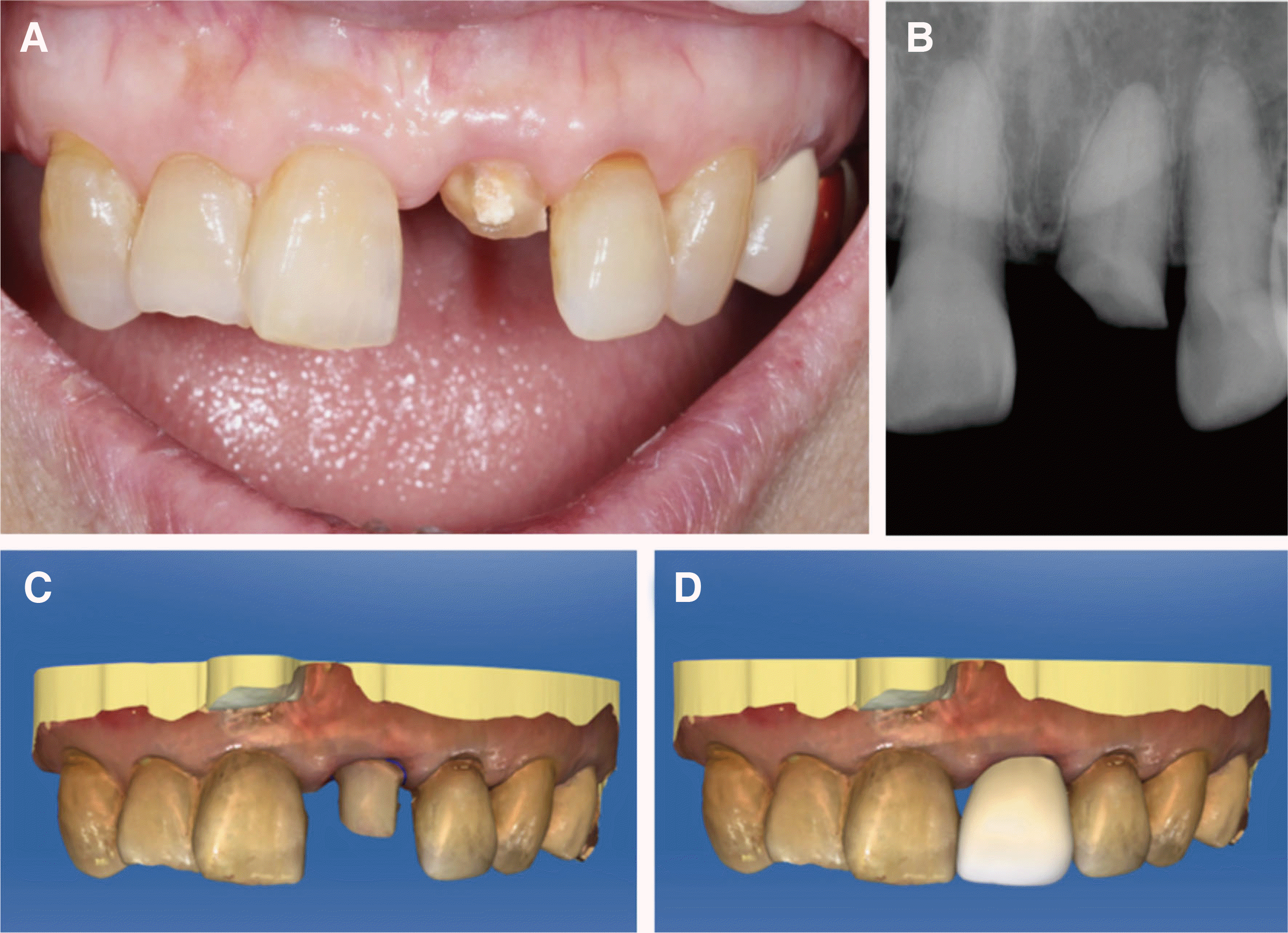 | Fig. 5(A) Intraoral photo and (B) Periapical radiographs. (C) Intraoral scan image after tooth preparation and (D) Virtual placement of the crown on computer-aided designing software using the “mirror image acquisition technique.” 
|
Single-visit root canal treatment was performed because there was no evidence of periapical pathosis (
Fig. 5B). Fiber post (DT Light-Post) cementation, resin core (Z100) restoration, and crown preparation were performed on the maxillary left central incisor. Digital impression of the tooth was taken with an intraoral scanner (CEREC AC omnicam) (
Fig. 5C). To determine the shade of the LS2 crown, a digital shade matching device (Vita Easyshade V) was used on the adjacent maxillary right central incisor. Shades of the cervical third and the mesial and distal marginal ridges were recorded as A3.5, and those of the middle and incisal third were recorded as A3.
The “copy and paste technique” could not be used because of the fractured maxillary left central incisor. Instead, the “mirror image acquisition technique” was performed on the intact maxillary right central incisor with the CAD/CAM software (
Fig. 5D). A new LS2 crown was milled with the CAD/CAM system (CEREC MC X), using an A2 LT block. The newly fabricated crown was tried-in before crystallization. Occlusion of the pre-crystallized crown was checked and carefully adjusted. The surface texture of the maxillary right central incisor was referred to for the surface characterization of the maxillary left central incisor. It showed vertical striae and surface irregularity. The surface characterization of the pre-crystallized LS2 crown was performed with a high-speed diamond bur (F102R). Thereafter, the staining procedure was performed. One coat of shade 1 was applied to the entire labial surface to reproduce the A3 shade. An additional coat of shade 1 was applied on the cervical third and both marginal ridges to reproduce the A3.5 shade. The characterized and glazed LS2 crown was crystallized in a ceramic furnace (Programat P310) and was allowed to cool for 10 min.
The internal surface of the crown was etched with 9.5% hydrofluoric acid (Porcelain etchant) and treated with a silane coupling agent (Monobond-S). The prepared tooth surface was etched with 37% phosphoric acid (ETCH-37
TM), rinsed with oil-free water for 20 s, and air-dried. Dentin adhesive (All-Bond Universal) was applied and light-cured. Final cementation was performed with a dual-cure resin cement (Duo-Link) under visible light with an intensity of 1200 mW/cm
2 (Bluephase G2) (
Fig. 6A, 6B).
 | Fig. 6(A) Intraoral photo and (B) Periapical radiograph after final cementation. 
|


 PDF
PDF Citation
 Print
Print


 XML Download