INTRODUCTION
Table 1
Table 2
Table 3
MAIN BODY
1. General concepts
1) Mechanisms of pain relief in POP, including PVP
2) Basic principle for needle insertion and selecting needle gauge sizes
3) Bone cement
4) Necessity of adjacent (facet) joint injections prior to POP (PVP)
5) Deciding whether to perform POP according to life expectancy of patients with bone metastases and evaluation for effectiveness of POP
Table 4
The lower KPS score and the higher the ECOG PS score, the worse the survival for most serious illness. The equivalences between the ECOG PS and KPS scores are expressed as 3 types of estimation: 1) point, 2) 66% confidence interval, and 3) 95% confidence interval equivalences. The point equivalences between ECOG PS and KPS scores are 0 = 100, 1 = 80, 2 = 70, 3 = 50, 4 = 30, and 5 = 0. The 66% confidence interval equivalences between the ECOG PS and KPS scores are 0 = 100-90, 1 = 90-70, 2 = 80-60, 3 = 60-40, 4 = 40-20, and 5 = 0. The 95% confidence interval equivalences between the ECOG PS and KPS scores are 0 = 100-80, 1 = 100-60, 2 = 90-50, 3 = 70-30, 4 = 50-10, and 5 = 0.
6) Diagnostic procedures for painful metastatic bony lesions
2. Percutaneous vertebroplasty (spinal POP)
1) Cervical vertebrae
(1) Atypical cervical vertebrae
① C1 vertebra
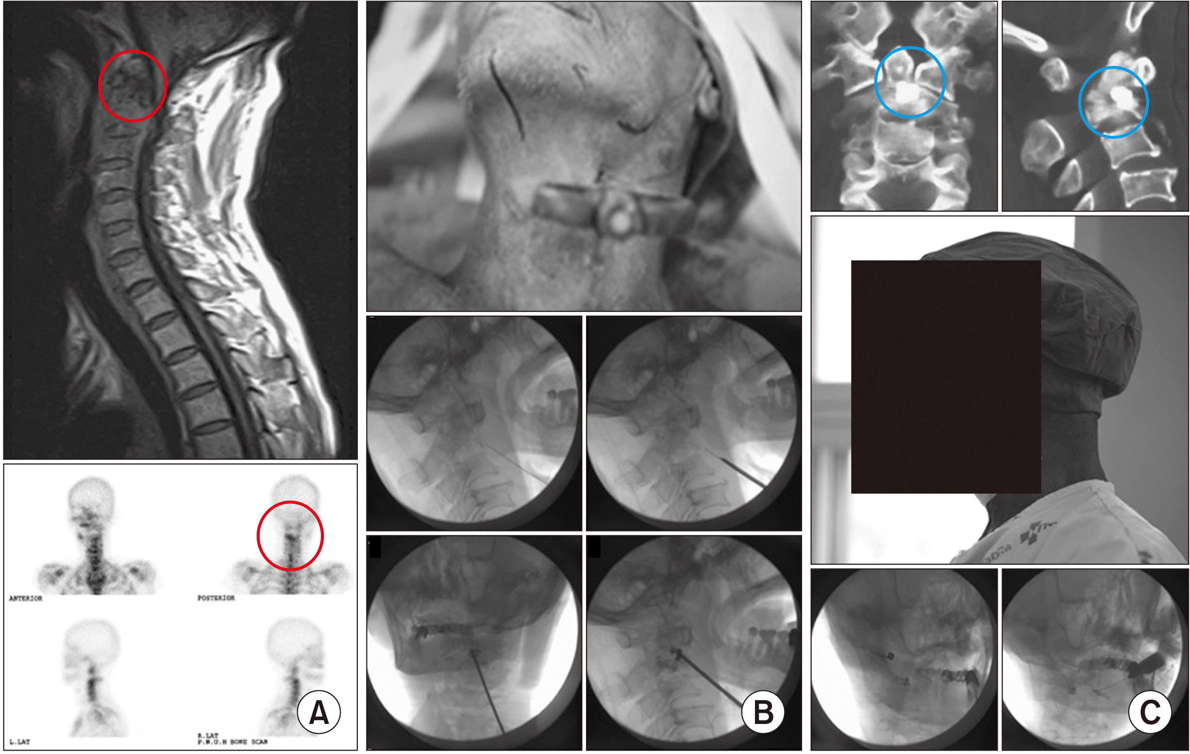
 | Fig. 1Percutaneous osteoplasty in the right lateral mass of the C1 vertebra (atlas). (A) Preoperative computed tomography and bone scans of a metastatic destructive lesion of the right lateral mass of the atlas. The red circle indicates a destructive bony metastatic lesion in the right lateral mass of the atlas from sagittal and axial views. The bone scans show an active lesion (the red circle) on the right lateral mass in the posterior view. The characteristic feature of the anterior view is the head tilted left, to the side opposite the lesion. (B) Intraoperative ultrasonic, exterior, and fluoroscopic views of the percutaneous osteoplasty for a metastatic destructive lesion of the right lateral mass of the atlas. (Upper left) Great caution should be given to the adjacent vulnerable anatomic structures, including the carotid artery, vertebral artery, and spinal nerves. (Upper right) A 13 gauge, 10 cm long vertebral needle is placed in the right lateral mass. (Lower left) The anterior posterior fluoroscopic view shows a vertebral needle, placed in the lateral mass. (Lower right) The lateral fluoroscopic view shows contrast medium without leakage into the vessels or epidural space. (C) Postoperative computed tomography and fluoroscopic views after percutaneous osteoplasty for a metastatic destructive lesion of the right lateral mass of the atlas. (Upper left and right) The purplish-white dot (within a blue circle) is located in the right lateral mass in the coronal and sagittal views. (Lower left and right) The black dot within a blue circle is located in the lateral mass in the anterior posterior view and lateral fluoroscopic views. |
② C2 vertebra
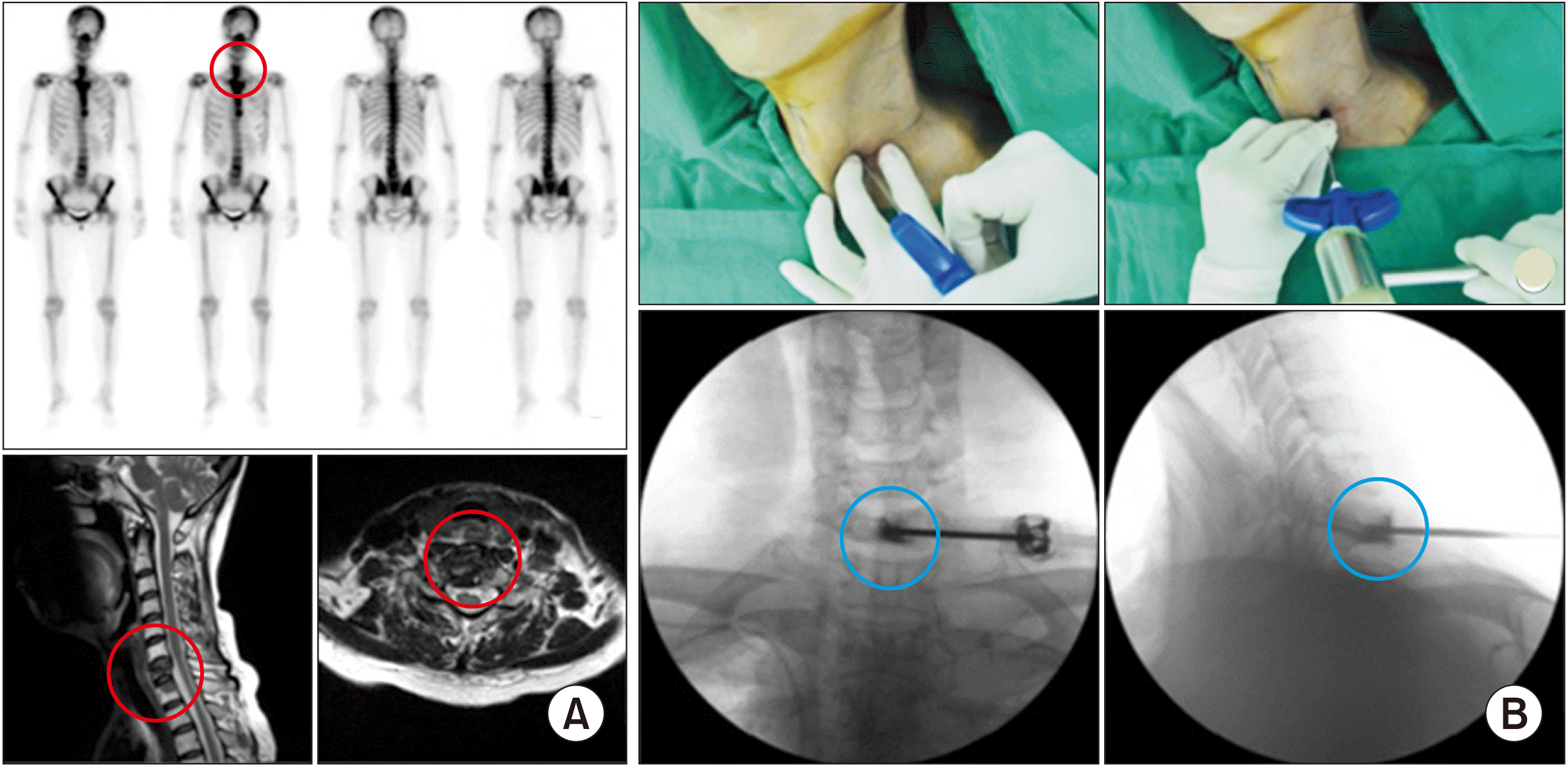
 | Fig. 2Percutaneous vertebroplasty at the C2 body and dens. (A) Preoperative magnetic resonance imaging shows a destructive lesion (the red circle), and bone scans also show an active bone lesion (the red circle) in the C2 body and dens. (B) Intraoperative percutaneous vertebroplasty at the C2 body and dens is performed using a 13 gauge, 10 cm vertebral needle along the 23 gauge, 10 cm spinal needle for local anesthetic infiltration. (C) (Upper) Postoperative computed tomography shows a proper filling of the destructive lesion with bone cement (the blue circle). (Middle) Patients can experience immediate pain relief and partially recover their necks’ range of motion. (Lower) Post- or pre-operative atlanto-occipital and atlanto-axial joint injection are commonly performed. |
(2) Typical cervical vertebrae (C3-C7)
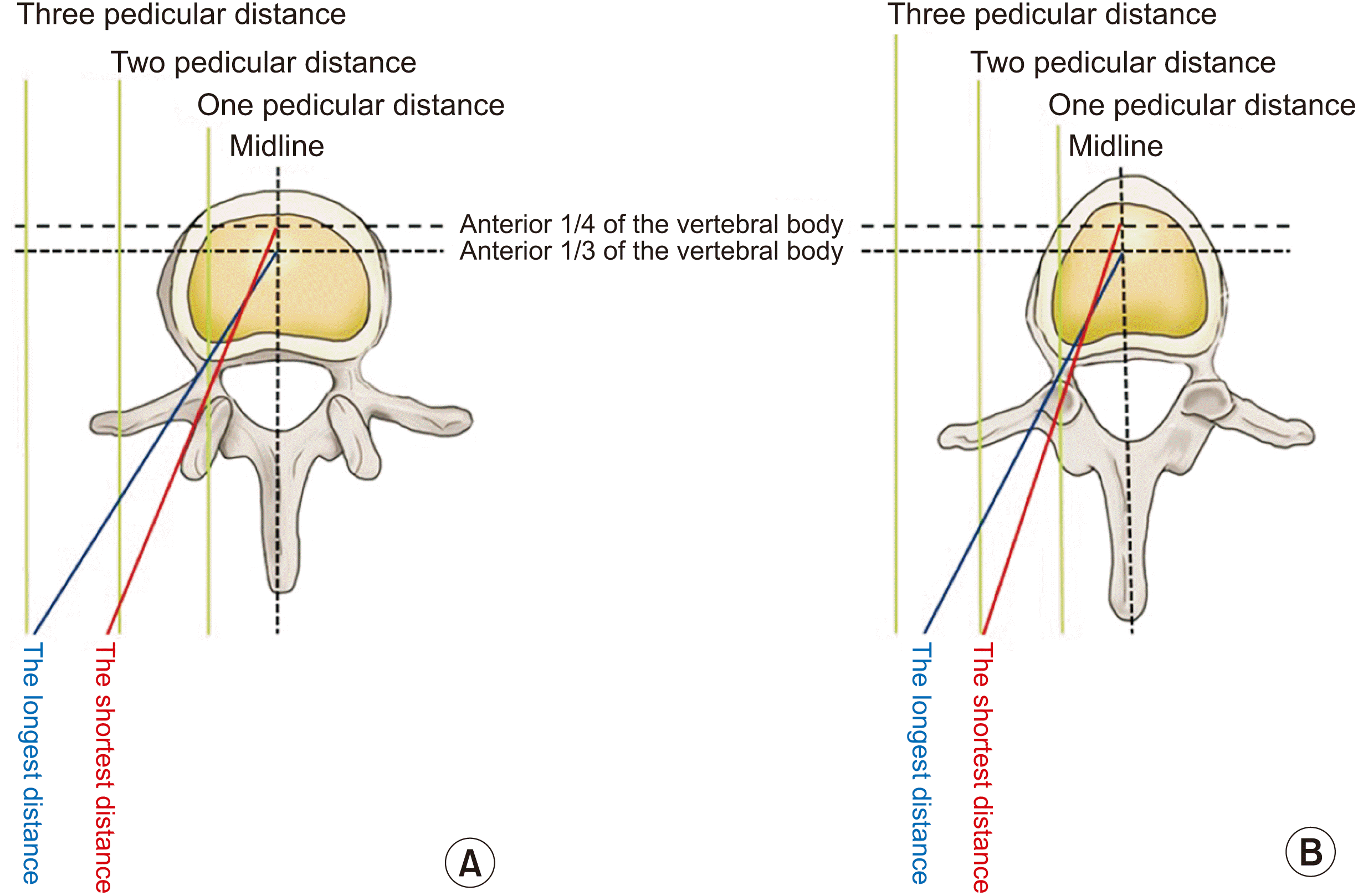
 | Fig. 3Percutaneous vertebroplasty at the C7 body. (A) Preoperative images: Bone scans shows an active lesion (the red circle) at the C7 vertebral body. Magnetic resonance imaging shows a destructive lesion (the red circle) at the C7 vertebral body. (B) Intraoperative images. (Upper left) After pushing the tracheoesophageal complex with the middle finger and palpating the internal carotid artery with the index finger, an 11 gauge, 10 cm vertebral needle is inserted and advanced into the anterior 1/3 of the vertebral body. (Upper right) Hammering is useful for anchoring the vertebral needle into the vertebral body through the slippery anterior longitudinal ligament. (Lower left) After confirmation of no leakage into the vessels or epidural space, bone cement (the blue circle) should be inserted into the destructive lesion. (Lower right) The target point of the needle is the anterior 1/3 of the vertebral body. Adapted from the article of Seo et al. (Korean J Anesthesiol 2013; 64: 276-9) [20]. |
2) Thoracic and lumbar vertebrae
(1) Transpedicular versus extrapedicular approach
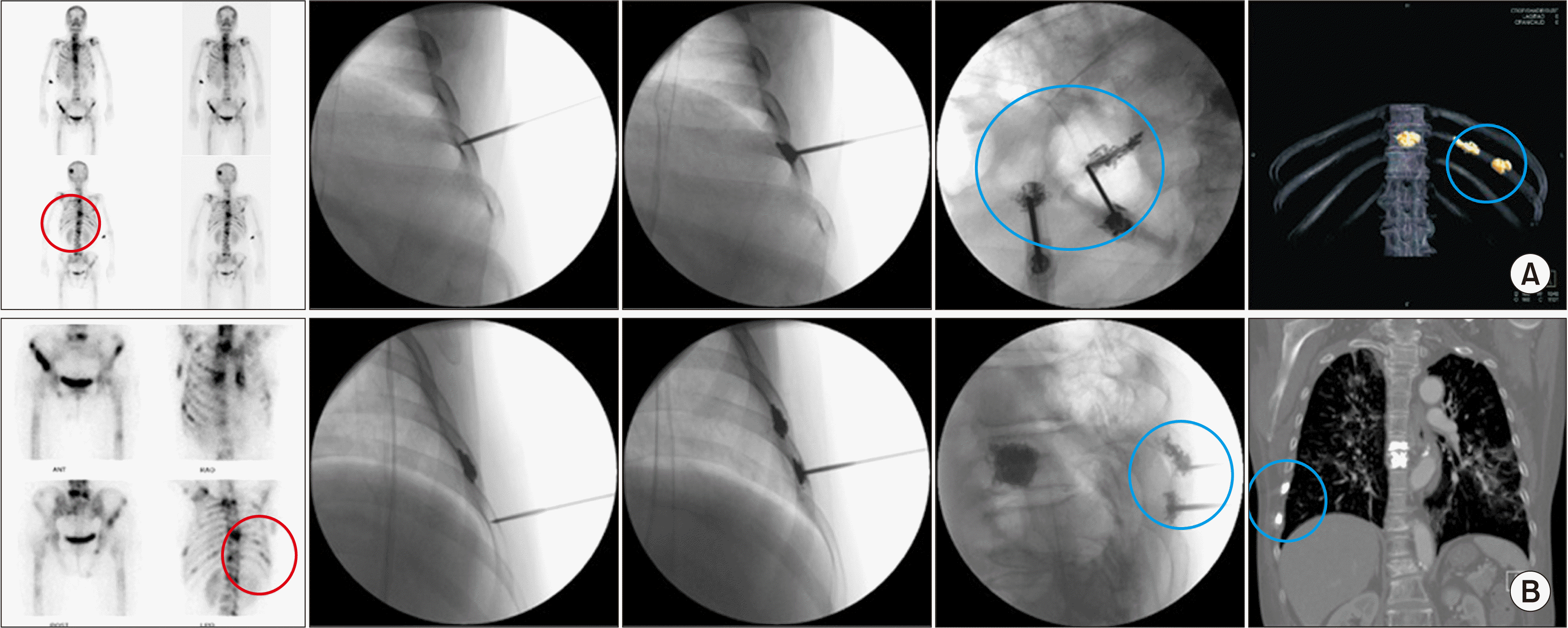
 | Fig. 4Imaginary lines for the unipedicular approach in percutaneous vertebroplasties (PVPs) of the lumbar and thoracic vertebrae. If a vertebral needle passes through the structure of the pedicle, the approach method should be called “a transpedicular approach” for PVP. If not, it should be called an “extrapedicular approach”. The vertebral needle should not penetrate the inner wall of the pedicle, so as not to pierce the spinal cord or dorsal root ganglion. The target point of the vertebral needle is the anterior 1/3 to 1/4 of the vertebral body. (A) In the lumbar vertebrae, the shortest distance from the midline is 2 pedicular distances, and the longest distance from the midline is 3 pedicular distances. (B) On the contrary, in the thoracic vertebrae, the shortest distance from the midline is 2 pedicular distances and the longest distance from the midline is 2.5 pedicular distances. |
① Unipedicular approach
② Extrapedicular approach
(2) Benign versus malignant painful thoracolumbar lesions
 | Fig. 5Percutaneous vertebroplasty for painful osteolytic vertebral compression fracture versus osteoporotic vertebral compression fracture at T11. The pedicle of the spine is strong enough to endure osteoporosis, however, it (and the posterior vertebral body) is vulnerable to spine metastases. (A) The anteroposterior fluoroscopic view shows no right pedicle (the red circle) in the metastatic vertebral osteolytic fracture, however, (B) there is an apparent right pedicle (the blue circle) in the osteoporotic vertebral compression fracture in the anteroposterior fluoroscopic view. |
3) Sacrum
(1) Sacral body
 | Fig. 6Sacroplasty in the first sacral vertebral body. (A) Sacral body. The vertebral needle is inserted in the left S1 vertebral body in the anteroposterior fluoroscopic view. Bone cement is inserted from the anterior sacral vertebral body to the middle of the sacral vertebral body in the lateral fluoroscopic view. Percutaneous vertebroplasty at L5 has already been done. (B) Sacral wing. The vertebral needle is inserted into the left sacral wing from the S1 to the S5, and then bone cement is inserted from the S5 to the S1 while withdrawing the needle in the anteroposterior and lateral fluoroscopic views, respectively. |
(2) Sacral wings (alae)
3. Extraspinal POP in malignant metastases
1) Bones in the thoracic cavity, scapula, and humerus
(1) Costoplasty
 | Fig. 7Costoplasty. (A) A 66-year-old woman, diagnosed with lung cancer, shows active bone lesions in the skull, multiple vertebrae, and multiple ribs. Preoperative bone scans show multiple active bone lesions (the red circle), especially in the ribs. Intraoperative anteroposterior and lateral fluoroscopic views shows that two 13 gauge, 5 cm vertebral needles are placed in the left 10th rib. Postoperative computed tomography shows 2 apparent yellow bone cement shadows (the blue circle) in the body of the left 10th rib. Bone cement has already been inserted in the T10 vertebral body. (B) An 80-year-old male, diagnosed with lung cancer, shows active bone lesions in multiple vertebrae and multiple ribs. He had already received percutaneous vertebroplasty at the T7 vertebral body. Bone cement was inserted twice at the different right 7th and 8th ribs. |
(2) Sternoplasty
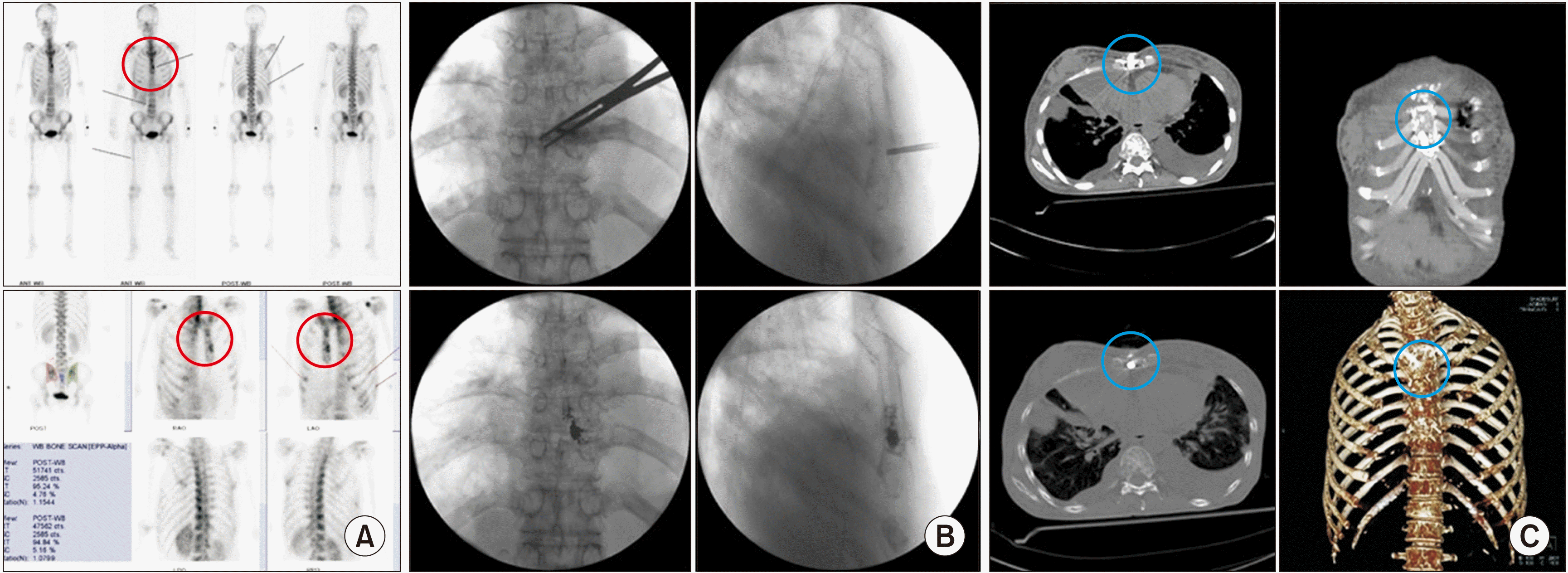 | Fig. 8Sternoplasty. A 49-year-old woman, diagnosed with breast cancer, complained of pain in breathing. (A) Preoperative bone scans. Tenderness on the mid-sternal body matches an active bone lesion (the red circle). (B) Intraoperative fluoroscopic views. An 11 gauge, 5 cm vertebral needle is inserted into the mid-sternal body. Kelly forceps are used for preventing the vertebral needle piercing the inner surface of the sternal body. Bone cement is inserted under lateral fluoroscopic monitoring. (C) Postoperative computed tomography. The inserted bone cement (the blue circle) is apparent in the sternum in axial computed tomography. |
(3) Scapuloplasty
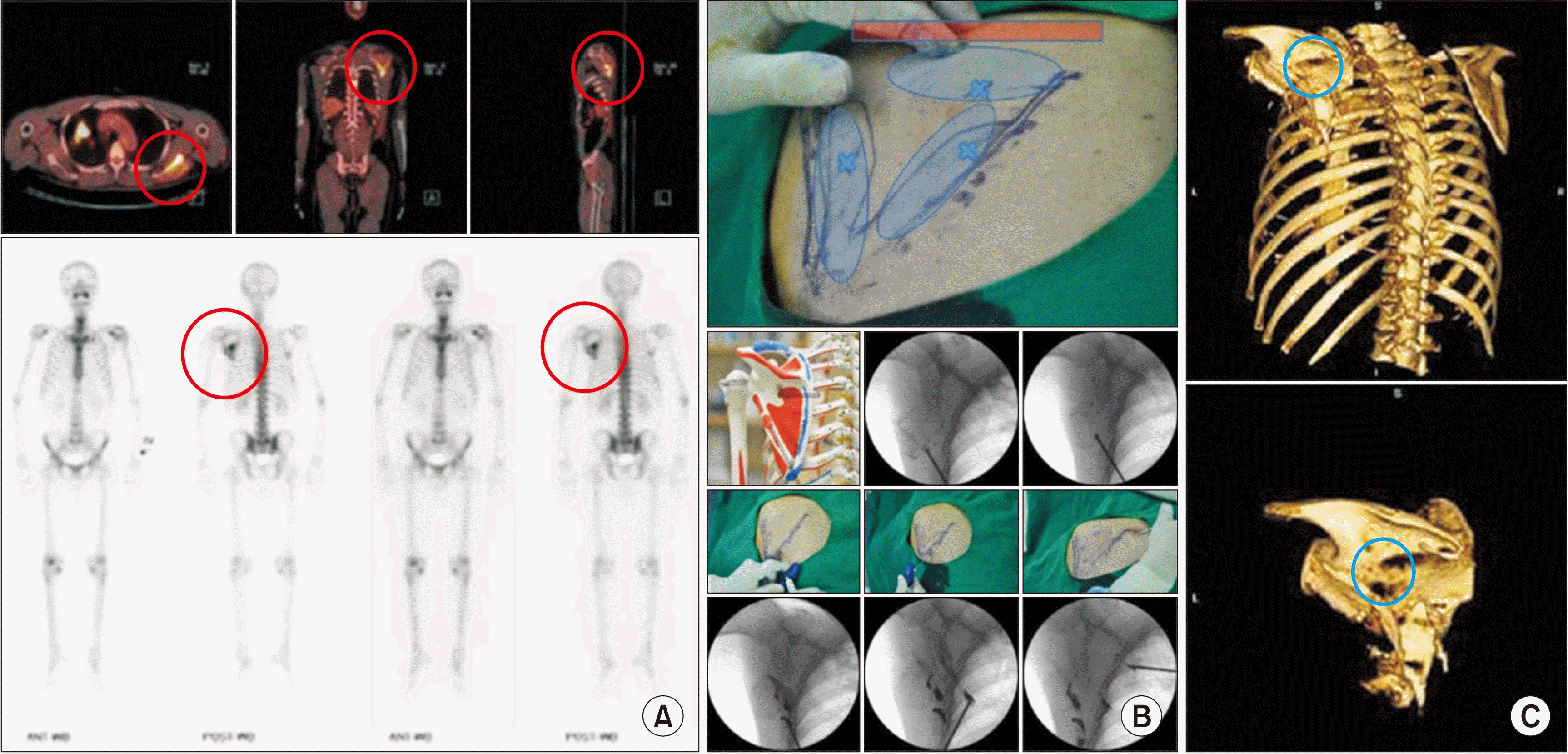 | Fig. 9Scapuloplasty. A 59-year-old man, diagnosed with lung cancer, complained of pain when he lay on his back and in a left lateral decubitus position. (A) Positron emission tomography-computed tomography shows a bright yellow lesion (the red circle) in the left scapula in axial, coronal, and sagittal sections. Bone scans also shows an active lesion on the left scapula (the red circle). Tender points matched these images. (B) Intraoperative images. Three tender points (the blue Xs), the medial and lateral borders, and scapular spine (the red bar) are drawn over the left scapula. Three vertebral needles are inserted from the inferior angle to the lateral and medial borders, and from the medial border to the middle of the scapula. (C) Postoperative computed tomography. Bone cement (the blue circle) is inserted after confirmation of no leakage using contrast medium. Adapted from the article of Choi et al. (Pain Physician 2010; 13: 485-91) [37]. |
(4) Humeroplasty
 | Fig. 10Humeroplasty. A 40-year-old woman, diagnosed with breast cancer, complained of left shoulder pain and limitation of motion. Tenderness on the left humeral head was noted. (A) Bone scans and positron emission tomography-computed tomography shows a lesion in the left humeral head (the red circle). (B) Bone cement is inserted through the 11 gauge, 10 cm vertebral needle in fluoroscopic views. (C) Postoperative computed tomography shows cement filling (the blue circle) in the left humeral head. |
2) Pelvic bones and femur
(1) Ilioplasty
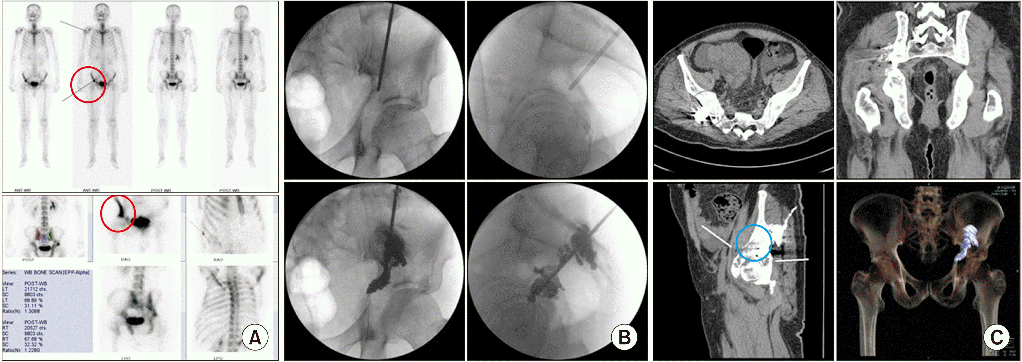 | Fig. 11Ilioplasty. A 61-year-old male, diagnosed with hepatocellular carcinoma, complained of right hip pain in a weight-bearing position. Tenderness was noted on the right ilium near the hip joint. (A) Preoperative bone scans show an active lesion (the red circle) in the right ilium. (B) A vertebral needle is inserted from the right iliac crest through the iliac wing, through the iliac body, and into the superior acetabulum in the anteroposterior and lateral fluoroscopic views. Bone cement is inserted from the right acetabulum to the iliac body in the anteroposterior and lateral fluoroscopic views. (C) Postoperative computed tomography shows injected bone cement (the blue circle) in the osteolytic lesion in the superior acetabulum and iliac body. |
(2) Ischioplasty
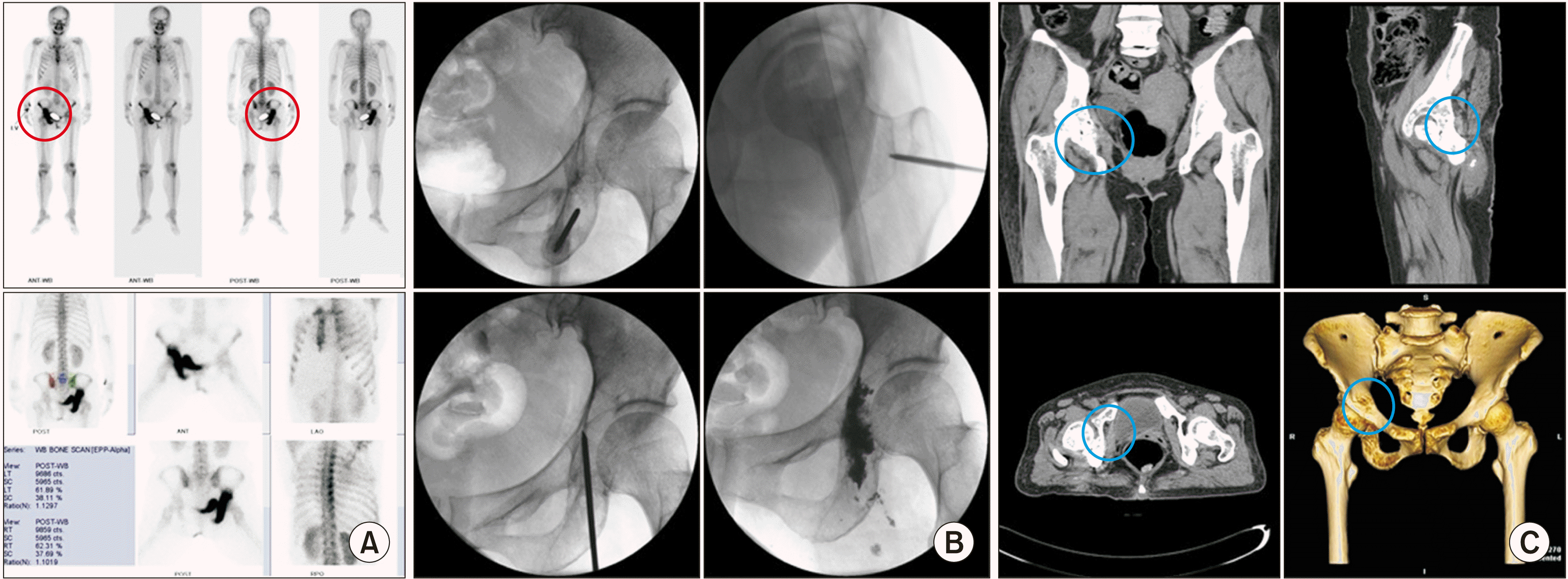 | Fig. 12Ischioplasty. A 47-year-old woman, diagnosed with adenocarcinoma of the lung, complained of right hip pain in a weight-bearing position. Tenderness was noted on the right ischium near the hip joint. (A) Preoperative bone scans show an active lesion (the red circle) on the right ischial body and inferoposterior acetabulum. (B) Intraoperative fluoroscopic views show that an 11 gauge, 10 cm vertebral needle is inserted from the right ischial tuberosity to the ischial body and inferoposterior acetabulum. (C) Postoperative computed tomography shows cement filling (the blue circle) in the right ischium. |
(3) Puboplasty
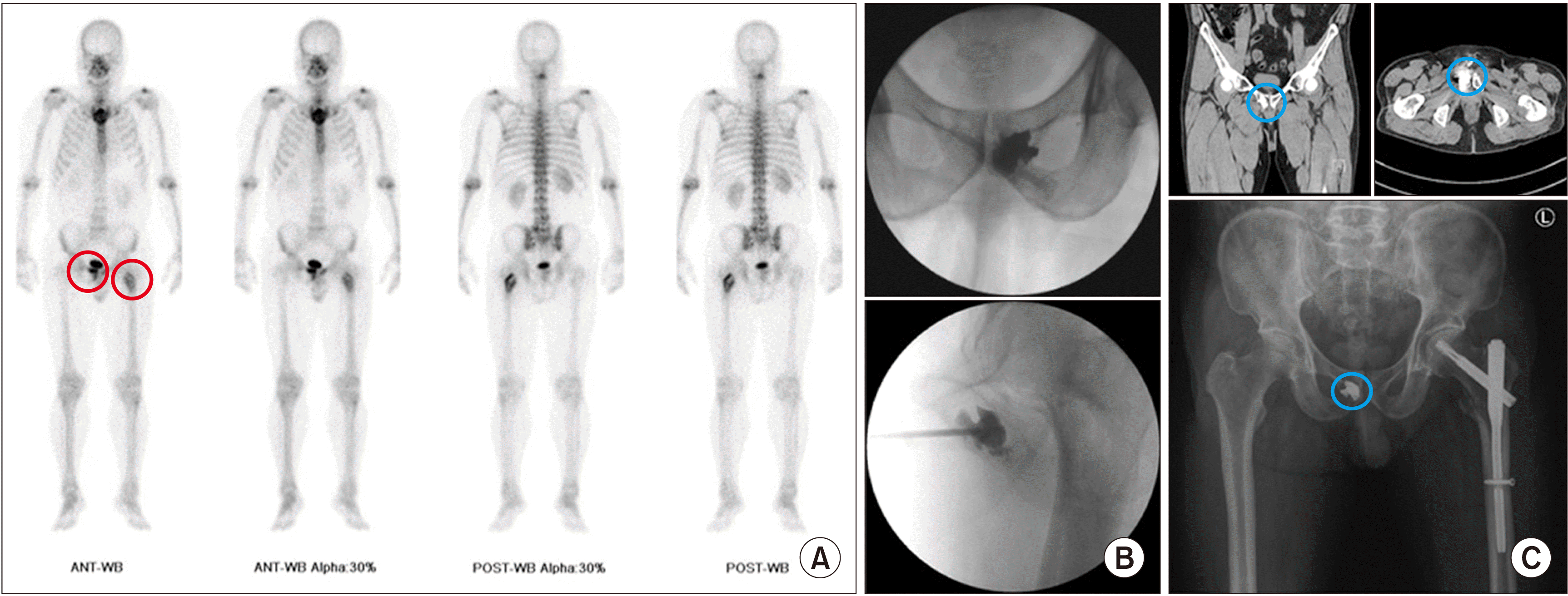 | Fig. 13Puboplasty. A 65-year-old man, diagnosed with hepatocellular carcinoma, complained of continuous pain in the pubis. Tenderness was more prominent on the right pubis and left femur. (A) Preoperative bone scans show active lesions (the red circle) on the right pubis and left femur. (B) An 11 gauge, 10 cm vertebral needle is inserted from the right pubic tubercle. (C) Postoperative computed tomography shows cement filling (the blue circle) in the right pubis. After puboplasty, intramedullary nail fixation, as a prophylactic surgery for intertrochanteric fracture in the left femur, was performed by an orthopedic surgeon. |
(4) Femoroplasty
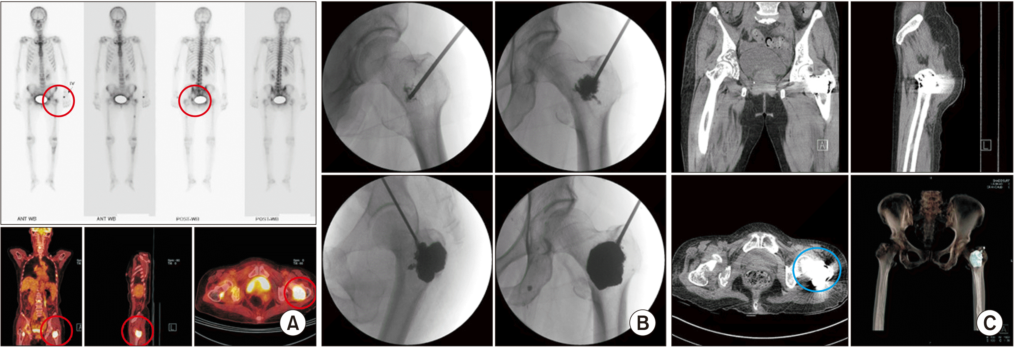 | Fig. 14Femoroplasty. A 73-year-old woman, diagnosed with hepatocellular carcinoma, complained of left hip pain. (A) Preoperative bone scans and positron emission tomography-computed tomography show an active lesion (the red circle) on the left femoral head. (B) An 11 gauge, 10 cm vertebral needle is inserted from the greater trochanter into the femoral head along the intertrochanteric line. (C) Postoperative computed tomography shows cement (the blue circle) filling in the left femoral neck. |
4. Extraspinal POP in OCLs (osteochondritis dissecans)
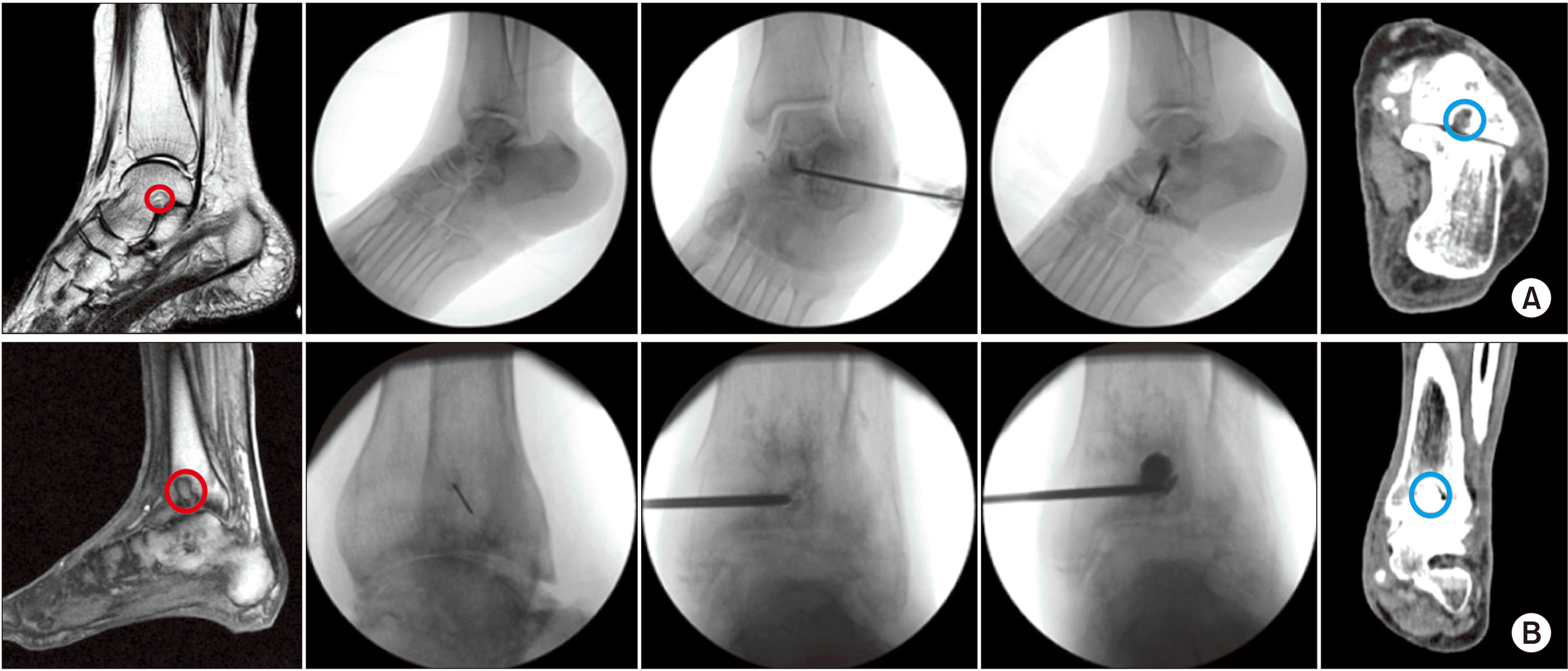 | Fig. 15Percutaneous osteoplasty (POP) for osteochondral lesions (OCLs) of the talus and tibia using calcium phosphate or hydroxyapatite bone cement. (A) POP at the OCL of the talus. Preoperative magnetic resonance imaging (MRI) shows an osteochondral lesion (the red circle) of the talus. Intraoperative fluoroscopic view shows insertion of a vertebral needle and bone cement (calcium phosphate or hydroxyapatite) after confirming no leakage into the joint or blood vessels. Postoperative computed tomography (CT) shows properly placed bone cement (the blue circle) in the OCLs of the talus. (B) POP at the OCL of the talus. Preoperative MRI shows an OCL of the tibia. After local infiltration, a 11 gauge, 10 cm vertebral needle is inserted. After confirmation of no leakage into the vessel, bone cement is injected. Postoperative CT shows proper cement (the blue circle) filling in the tibia. Adapted from the article of Ri et al. (Korean J Pain 2013; 26: 164-8) [10]. |
 | Fig. 16Percutaneous osteoplasty (POP) for osteochondral lesion (OCL) of the talus under arthroscopic monitoring. (A) Preoperative magnetic resonance imaging and bone scans reveal an OCL (the red circle) of the talus. (B) Intraoperative POP using calcium phosphate or hydroxyapatite bone cement after aspiration of joint fluid under fluoroscopy and arthroscopy. (C) Postoperative plain X-ray and computed tomography show inserted bone cement (the blue circle). Adapted from the article of Seo et al. (Pain Physician 2012; 15: E743-8) [42]. |


 PDF
PDF Citation
 Print
Print


 XML Download