Journal List > Neurointervention > v.8(1) > 1150677

Park, Lee, Lim, Min, Nguyen, Ko, Yoon, and Suh: Computational Modeling with Fluid-Structure Interaction of the Severe M1 Stenosis Before and After Stenting

Abstract

Purpose

Image-based computational models with fluid-structure interaction (FSI) can be used to perform plaque mechanical analysis in intracranial artery stenosis. We described a process in FSI study applied to symptomatic severe intracranial (M1) stenosis before and after stenting.

Materials and Methods

Reconstructed 3D angiography in STL format was transferred to Magics for smoothing of vessel surface and trimming of branch vessels and to HyperMesh for generating tetra volume mesh from triangular surface-meshed 3D angiogram. Computational analysis of blood flow in the blood vessels was performed using the commercial finite element software ADINA Ver 8.5. The distribution of wall shear stress (WSS), peak velocity and pressure was analyzed before and after intracranial stenting.

Results

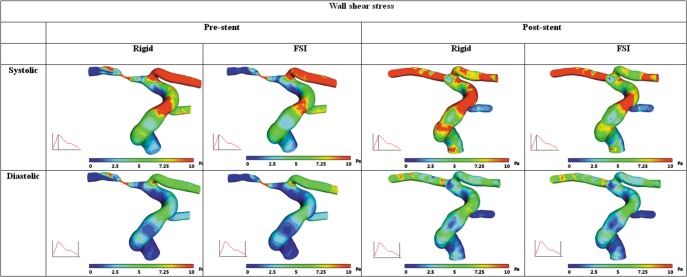
The wall shear stress distributions from Computational fluid dynamics (CFD) simulation with rigid wall assumption as well as FSI simulation before and after stenting could be compared. The difference of WSS between rigid wall and compliant wall model both in pre- and post-stent case is only minor except at the stenosis region. These WSS values were greatly reduced after stenting to 15~20 Pa at systole and 3~5 Pa at end-diastole in CFD simulation, which are similar in FSI simulations.

Conclusion

Our study revealed that FSI simulation before and after intracranial stenting was feasible despite of limited vessel wall dimension and could reveal change of WSS as well as flow velocity and wall pressure.

Because intracranial atherosclerotic stenosis is angiographically more common than extracranial lesions in Koreans, intracranial stenting has been performed more frequently than in Western countries [1-3]. Although intracranial angioplasty and/or stenting is believed to be beneficial for patients who are resistant to medical treatment, appropriate indication of intracranial stenting and long term outcome data is still not sufficient [4-6].
Although final luminal diameter after stenting is critical for the patient outcome, hemodynamic factors prone to adverse events or restenosis leading to target vessel revascularization in the intracranial artery have not been well demonstrated [4]. Few studies of the hemodynamics in small-caliber intracranial vessels have been conducted especially in vessels associated with severe stenosis [5-10]. The reason of the difficulties to apply this computational fluid dynamics (CFD) research to intracranial artery is in part due to the limited resolution of stenotic lumen imaged by current technologies because resolution of target vessel has precluded the development of a realistic geometry for use in finite element modeling and CFD analysis [11, 12].
We developed a process of CFD technique to elucidate the local hemodynamics as a result of atherosclerosis of the small intracranial arteries before and after intracranial stenting. CFD studies, however, do not usually consider the compliance of arterial wall due to the complexity of the numerical modeling and the need for a fluid structure interaction (FSI) environment to solve for the coupled fluid/structure problem has been arisen [13]. Therefore, we describe the FSI application intracranial stenosis before and after stenting and compared with CFD.

MATERIALS AND METHODS

Subject-specific Geometry Reconstruction

A 65-year-old male patient who presented with right arm weakness revealed an acute focal cortical ischemic change in the borderzone type on the diffusion-weighted image (not shown). He had diabetes mellitus and history of alcohol. He did not have arterial fibrillation or any coagulation disorders. He underwent angioplasty which was followed by stenting in the right M1 stenosis. Driver (Medtronic Ireland, Minneapolis, MN) with 2.25 mm diameter and 8 mm length were deployed to 2.35 mm diameter at 12 atmosphere of balloon pressure. Angiogram was obtained before and after stenting. Our Institutional Review Board approved this study, and we obtained written informed consent from the patient.
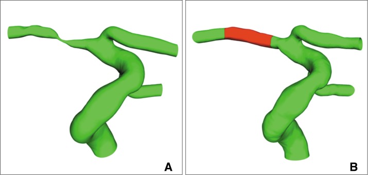
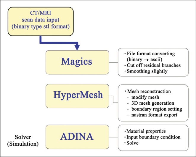
Three-dimensional (3D) rotational angiography was obtained in AXIOM Artis Zee (Siemens, Erlangen, Germany) and then the images were transferred to Syngo workstation (version VB 15D) to generate 3D angiography with reducing FOV and adjusting the target vessel. The final image was transformed to STL format in 256 × 256 pixels. After smoothing of vessel surface and trimming of branch vessels in Magics RP (Materialise, Belgium), the 3-D geometry was transferred to HyperMesh (Altair Engineering, Inc., New Zealand) to create tetrahedral elements for CFD (Fig. 1). 3D reconstructed geometries before and after stent implantation were shown in Fig. 2.

Computational Fluid Dynamics

In the current study, we carried out CFD and fully coupled FSI simulations with an assumption of rigid wall and compliant wall, respectively. Blood flow was assumed to be Newtonian, homogeneous flow with density 1050 kg/m3, viscosity of 3.5 × 10⁻³ Pa·s. The SI physical unit of dynamic viscosity is the pascalsecond (Pa·s), (equivalent to N·s/m2, or kg/(m·s)). To achieve true boundary conditions corresponding with patient-specific, flow velocity before and after installed stent were obtained by transcranial Doppler ultrasounds method from gated phase contrast MR angiography in an age-matched male. Pulsatile flow rates waveform based on in vivo measurement data was specified at the posterior communicating artery, the anterior cerebral artery and the middle cerebral artery for pre- and post-stent simulations respectively and time-varying pressure condition according to Perktold et al. [14] was imposed in the internal carotid artery inlet.
In simulations with compliant wall model, intracranial arterial wall and plaque components were assumed to be isotropic, linear, elastic with a constant Young Modulus E = 2.6 × 10⁵ Pa, density of p = 1000 kg/m3 and a Poisson's ratio v = 0.49. To simplify the complex stent geometry, stent was modeled as shell type tube with mechanical property of density E = 2.2 × 10¹¹Pa, p = 8420.39 kg/m3 and Possion's ratio v = 0.234 (Co-Cr Alloy, ASTM F563). The arterial wall thickness was considered to be constant as 0.5 mm.
Computational analysis of blood flow in intracranial blood vessels was performed using the commercial finite element software ADINA version 8.7.2 (ADINA R & D, Inc., Lebanon, MA, USA). Fluid domain was divided into 525,659 tetrahedral elements and elastic wall discretization yielded 77,264 shell elements for pre-stent case. Because of rigorously complicated flow field through stenosis, dense mesh with gradual ratio change from normal to lesion region was required and especially computational mesh had the highest density around stenosis region. In case of post-stent model, 354,009 tetrahedral fluid elements and 55,359 shell elements were used for fluid and structure domain respectively. In order to prevent torsion and rotation of vessel, constraints at intracranial ends were placed and rotation motions around global coordinate axis system were fixed. No-slip boundary condition was applied for whole interface between fluid and structure. We compared difference of WSS before and after stenting regarding to Maximum WSS at systole and enddiastole.

RESULTS

The wall shear stress distributions from CFD simulation with rigid wall assumption as well as FSI simulation before and after stenting were compared in Fig. 2. Overall, the difference of WSS between rigid wall and compliant wall model both in pre- and post-stent case is only minor except at the stenosis region. In the case of pre-stenting, FSI simulation created noticeable reduction of maximum WSS at the stenosis compared to the simulation with rigid wall assumption.
Before stent implantation, maximum WSSs at the stenosis were calculates as 167 Pa at systole and 109 Pa at end-diastole in CFD simulation with rigid wall assumption and as 138 Pa at systole and 104 Pa at end-diastole in FSI simulation with considering wall compliance (Fig. 3). These WSS values were greatly reduced after stenting to 15~20 Pa at systole and 3~5 Pa at end-diastole in CFD simulation, which are similar in FSI simulations.
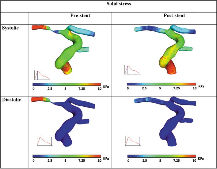
Fig. 4 shows Von Mises structural stress before and after stent implantation. This revealed that the structural stress at the stenosis region is not rather high compared with the one on normal vessel, but in similar range even before implanting stent. This implies that WSS may play more important role in plaque rupture by fissuring of thin fibrous cap than structural stress on plaque.

DISCUSSION

Fluid-structure interaction (FSI) analysis has been employed as a powerful tool because it combines blood flow simulation through CFD with wall tensile stress (WTS) analysis in the plaque region by the finite element method [15]. Blood flow through a compliant artery requires appropriate fluid-structure coupling in order to account for the interaction between the flowing blood and the deforming arterial wall [16]. With anatomically realistic plaque geometry, FSI simulation is able to provide detailed stress analysis for the plaque which has been demonstrated with individual case studies [17]. As we could demonstrated the difference of FSI compared to CFD without considering the FSI, ultimately it is hoped that biomechanical simulations based on patient-specific data will serve as a reliable and robust clinical tool in the characterization of lesions and choice of treatment plan [18].
Although various arterial sites have been analyzed by FSI such as the carotid arterial bifurcation, an abdominal aortic aneurysm model due to relative ease of imaging and simpler physical boundary conditions, and a stented aortic aneurysm model, our results revealed that the application of CFD and FSI can also be possible in the intracranial vessels which has small diameter in the range of 2 - 3 mm [13, 19, 20]. Risk assessment based solely on the degree of luminal stenosis will tend to underestimate the severity of the atherosclerotic lesion. For these reasons, there is a need for more sensitive methods to risk stratify patients with intracranial atherosclerotic disease.
Currently, patient-specific 3D FSI simulations suffer from two major bottle necks in terms of the time required to get from medical images to mechanical stress and strain predictions. The first challenge is the generation of a suitable computational mesh that can accurately represent the components of the diseased artery and can provide meaningful numerical results. The second challenge relates to the time and computational resources required to solve realistic finite element models on a patient-specific basis. The two challenges are inter-related, and reduction of one generally means an increase in the other [18]. To estimate stress levels in the fibrous cap, FSI analysis has emerged as a tool combining blood-flow simulation through CFD with finite element analysis of the corresponding stress levels in the surrounding tissues [21].
This study has some limitations. Intrinsically, vessel wall is nonlinear hyperelastic material and even its properties vary with locations and the components of vessel, in particular, at the stenosis with plaque. We assumed linear elastic and constant over whole vessel for simplification of computational modeling. We do note, however, that our finding that WSS would be essential in plaque rupture compared to structural stress in the perspective of hemodynamics would hold because the narrower and thicker vessel in stenosis is, the less structural stress, but higher WSS would be produced. We also assumed the stent as shell type tube instead of real stent geometry. However, this would be proper assumption in modeling because real stent would be relatively rigid after implantation with outward expanding narrowed vessel. The assumption of Newtonian rheology made in this study have also shown to be of relatively minor influence on hemodynamic characteristics in large vessel [22].

Acknowledgements and Funding

This work was partly supported by a grant from National Research Foundation of Korea (2010-0025683).

References

1. Suh DC, Lee SH, Kim KR, Park ST, Lim SM, Kim SJ, et al. Pattern of atherosclerotic carotid stenosis in Korean patients with stroke: different involvement of intracranial versus extracranial vessels. AJNR Am J Neuroradiol. 2003; 24:239–244. PMID: 12591640.
2. Gorelick PB, Caplan LR, Hier DB, Parker SL, Patel D. Racial differences in the distribution of anterior circulation occlusive disease. Neurology. 1984; 34:54–59. PMID: 6537853.
crossref
3. Sacco RL, Kargman DE, Gu Q, Zamanillo MC. Race-ethnicity and determinants of intracranial atherosclerotic cerebral infarction. The Northern Manhattan Stroke Study. Stroke. 1995; 26:14–20. PMID: 7839388.
4. Suh DC, Kim JK, Choi JW, Choi BS, Pyun HW, Choi YJ, et al. Intracranial stenting of severe symptomatic intracranial stenosis: results of 100 consecutive patients. AJNR Am J Neuroradiol. 2008; 29:781–785. PMID: 18310234.
crossref
5. Choi JW, Kim JK, Choi BS, Lim HK, Kim SJ, Kim JS, et al. Angiographic pattern of symptomatic severe M1 stenosis: comparison with presenting symptoms, infarct patterns, perfusion status, and outcome after recanalization. Cerebrovasc Dis. 2010; 29:297–303. PMID: 20090322.
crossref
6. Suh DC, Sung KB, Cho YS, Choi CG, Lee HK, Lee JH, et al. Transluminal angioplasty for middle cerebral artery stenosis in patients with acute ischemic stroke. AJNR Am J Neuroradiol. 1999; 20:553–558. PMID: 10319958.
7. Groen HC, Gijsen FJ, van der Lugt A, Ferguson MS, Hatsukami TS, van der Steen AF, et al. Plaque rupture in the carotid artery is localized at the high shear stress region: a case report. Stroke. 2007; 38:2379–2381. PMID: 17615365.
8. Groen HC, Gijsen FJ, van der Lugt A, Ferguson MS, Hatsukami TS, Yuan C, et al. High shear stress influences plaque vulnerability Part of the data presented in this paper were published in Stroke 2007;38:2379-81. Neth Heart J. 2008; 16:280–283. PMID: 18711619.
9. Malek AM, Alper SL, Izumo S. Hemodynamic shear stress and its role in atherosclerosis. JAMA. 1999; 282:2035–2042. PMID: 10591386.
crossref
10. Choi JW, Kim JK, Choi BS, Kim JH, Hwang HJ, Kim JS, et al. Adjuvant revascularization of intracranial artery occlusion with angioplasty and/or stenting. Neuroradiology. 2009; 51:33–43. PMID: 18818910.
crossref
11. Oh TS, Ko YB, Park ST, Yoon KH, Lee SW, Park JW, et al. Computational Flow Dynamics Study in Severe Carotid Bulb Stenosis with Ulceration. Neurointervention. 2010; 5:97–102.
crossref
12. Suh DC, Park ST, Oh TS, Park SO, Lim OK, Park SC, et al. High shear stress in systolic phase at the surface of the enhancing plaque is related to symptom presentation of the severe M1 stenosis. Korean J Radiol. 2011; 12:515–518. PMID: 21852914.
13. Kim YH, Kim JE, Ito Y, Shih AM, Brott B, Anayiotos A. Hemodynamic analysis of a compliant femoral artery bifurcation model using a fluid structure interaction framework. Ann Biomed Eng. 2008; 36:1753–1763. PMID: 18792781.
crossref
14. Perktold K, Rappitsch G. Mathematical modeling of arterial blood flow and correlation to atherosclerosis. Technol Health Care. 1995; 3:139–151. PMID: 8749862.
crossref
15. Gao H, Long Q, Graves M, Gillard JH, Li ZY. Carotid arterial plaque stress analysis using fluid-structure interactive simulation based on in-vivo magnetic resonance images of four patients. J Biomech. 2009; 42:1416–1423. PMID: 19464011.
crossref
16. Kanyanta V, Ivankovic A, Karac A. Validation of a fluid-structure interaction numerical model for predicting flow transients in arteries. J Biomech. 2009; 42:1705–1712. PMID: 19482285.
crossref
17. Tang D, Yang C, Mondal S, Liu F, Canton G, Hatsukami TS, et al. A negative correlation between human carotid atherosclerotic plaque progression and plaque wall stress: in vivo MRI-based 2D/3D FSI models. J Biomech. 2008; 41:727–736. PMID: 18191138.
crossref
18. Leach JR, Rayz VL, Mofrad MR, Saloner D. An efficient two-stage approach for image-based FSI analysis of atherosclerotic arteries. Biomech Model Mechanobiol. 2010; 9:213–223. PMID: 19756798.
crossref
19. Suh DC, Park ST, Oh TS, Park SO, Lim OK, Park S, et al. High shear stress at the surface of enhancing plaque in the systolic phase is related to the symptom presentation of severe M1 stenosis. Korean J Radiol. 2011; 12:515–518. PMID: 21852914.
crossref
20. Suh DC, Ko YB, Park ST, Yoon KH, Lim OK, Oh JS, et al. Computational flow dynamics of the severe M1 stenosis before and after stenting. Neurointervention. 2011; 6:13–16. PMID: 22125742.
crossref
21. Kock SA, Nygaard JV, Eldrup N, Frund ET, Klaerke A, Paaske WP, et al. Mechanical stresses in carotid plaques using MRI-based fluid-structure interaction models. J Biomech. 2008; 41:1651–1658. PMID: 18485351.
crossref
22. Lee SW, Steinman DA. On the relative importance of rheology for image-based CFD models of the carotid bifurcation. J Biomech Eng. 2007; 129:273–278. PMID: 17408332.
crossref
Fig. 1
Analysis process for computational fluid dynamic approach.
ni-8-23-g001
Fig. 2
Computational model for FSI in the severe M1 stenosis. Angiograms before (A) and after (B) stenting show relieved severe stenosis of the right M1 and normalization of decreased size and filling of the right MCA branches after stenting. Different material components were assumed for the stented and non-stented vessel in (B).
ni-8-23-g002
Fig. 3
Wall shear stress distributions before and after stent implantation.
ni-8-23-g003
Fig. 4
Solid stress (Von Mises stress) distributions before and after stent implantation.
ni-8-23-g004
TOOLS
Similar articles