Abstract
Objective
To identify optimal areas for the insertion of extra-alveolar miniscrews into the infrazygomatic crest (IZC) and mandibular buccal shelf (MBS), using cone beam computed tomography (CBCT) imaging in patients with different craniofacial patterns.
Methods
CBCT reconstructions of untreated individuals were used to evaluate the IZC and MBS areas. The participants were divided into three groups, based on the craniofacial pattern, namely, brachyfacial (n = 15; mean age, 23.3 years), mesofacial (n = 15; mean age, 19.24 years), and dolichofacial (n = 15; mean age, 17.79 years). In the IZC, the evaluated areas were at 11, 13, and 15 mm above the buccal cusp tips of the right and left first molars. In the MBS, the evaluated areas were at the projections of the first molars’ distal roots and second molars’ mesial and distal roots, at a 4- and 8-mm distance from the cementoenamel junction. Intergroup comparisons were performed with analysis of variance and the Tukey test.
Results
There was no statistically significant difference in the IZC bone thickness among the groups. For MBS bone availability, some comparisons revealed no difference; meanwhile, other comparisons revealed increased MBS bone thickness in the brachyfacial (first molars distal roots) and dolichofacial (second molars mesial and distal roots) patterns.
Conclusions
There was no significant difference in the IZC bone thickness among the groups. The facial skeletal pattern may affect the availability of ideal bone thickness for the insertion of extra-alveolar miniscrews in the MBS region; however, this variability is unlikely to be clinically meaningful.
Newton’s third law of physics applies to the movement of teeth that are subject to repositioning interventions. Orthodontists have developed various anchorage management approaches to help control active and reactive units, using anchorage derived from differential numbers of teeth, extra-oral forces, intraoral elastics, auxiliary wires such as transpalatal bars, and moment/force ratios with segmented mechanics, all of which have had variable success.1
Nowadays, temporary skeletal anchorage devices such as miniscrews and miniplates are frequently used. Compared to miniplates, miniscrews are less expensive and technically easier to place and remove; despite being less versatile in terms of direction and intensity of force application, they are popular and can be placed by an orthodontist.1
Factors that affect successful miniscrew placement are primary stability and distances to key anatomical structures such as dental roots and major blood vessels, among others.2 To improve survival rates and obtain better biomechanical application vectors, orthodontists have examined the impact of placing intra-radicular screws both on the buccal and lingual sides of the alveolus,3 and in the extra-alveolar positions at the retromolar area, with the hard palate either on the suture or lateral to it,2,4 as well as in the infrazygomatic crest (IZC)5 and mandibular buccal shelf (MBS).6 Compared to intra-radicular miniscrews, the latter two types allow to move the dentition with the application of an immediate and direct force to the dental arches without concerns of moving teeth against the miniscrews.
The MBS is defined as the area buccal to the roots of lower first and second molars and mesial to the oblique line of the mandibular body.7 In the first molar mesial root region, this area is relatively steep and becomes progressively flatter towards the third molars. The IZC is the area in the zygomatic buttress at the level of the maxillary first and second molars, between the buccal roots and the buccal cortical bone of the maxilla.8 It comprises both cortical and medullar bone, with the superior limit being the maxillary sinus cortical bone. For the MBS, there is evidence that the best position to place the miniscrew is the region of the distal cusp of the lower second molars.7,9,10 For the IZC, the region between the first and second molars is the most frequently recommended site.8
Previous studies have shown differences among short-, average-, and long-faced patients in the thickness of the cortical bone11,12 and in the total bucco-lingual width of the alveolar bone,13,14 favoring short-faced individuals. Consequently, the thickness of the MBS and IZC, which comprise both cortical bone and alveolar bone, may vary, depending on facial type. This study aimed to use cone beam computed tomography (CBCT) scanning to identify the optimal areas for the insertion of extra-alveolar mini screws in the IZC and MBS regions of individuals with different craniofacial patterns in the Brazilian population.
This study was approved by the Ethics in Research Committee of Bauru Dental School – University of São Paulo (619.057/2014). The sample size of this cross-sectional study was calculated based on an alpha of 0.05 and a beta of 0.2 to achieve 80% power to detect a minimum difference of 1.15 mm with a standard deviation (SD) of 1.07 mm in the MBS thickness10 and a minimum difference of 0.86 mm with an SD of 0.78 mm in the IZC.15 The sample size calculation showed that 15 patients were required per group.
The initial sample included CBCT records of 78 participants selected from a digital archive of a private practice. The CBCT examinations were performed between June 2012 to November 2015. The sample comprised Brazilians of southern European descent (Italians, Portuguese, and Spanish). The exclusion criteria were the absence of the second permanent molar, presence of any remaining deciduous teeth, metal prostheses or restorations, history of periodontal disease, and previous orthodontic treatment. After the exclusion criteria were applied, the remaining sample was divided into three groups according to vertical facial patterns determined by the Ricketts VERT.16
Group 1 (brachyfacial type) consisted of 15 patients (7 male and 8 female) with the mean age of 22.20 years (SD = 7.40; range, 14.83–35.75), who presented with the VERT index values of > 0.5, with predominantly horizontal growth. Group 2 (mesofacial type) consisted of 15 patients (6 male and 9 female) with the mean age of 19.24 years (SD = 5.92; range, 14.41–37.58), who presented with the VERT index values between –0.5 and 0.5. Group 3 (dolichofacial type) consisted of 15 patients (7 male and 8 female) with the mean age of 17.79 years (SD = 3.63; range, 14.83–35.75), who presented VERT index values of < –0.5, with predominantly vertical growth17 (Table 1).
CBCT images were taken in an i-CAT Classic unit (Imaging Sciences International, Hatfield, PA, USA); the subjects were positioned with the Frankfurt horizontal plane parallel to the floor and instructed to maintain maximum intercuspation with the tongue, touching the palate, and to avoid swallowing during the scanning period. The imaging protocol involved 120 kV, 8 mA, 13 × 16 cm field of view, 0.30 mm voxel size, and scanning time of 20 seconds. Images were saved in Digital Imaging and Communications in Medicine (DICOM) files, which were imported into Dolphin 3-dimensional (3D) software (version 11.9; Dolphin Imaging and Management Solutions, Chatsworth, CA, USA) to obtain the primary reconstructed images (sagittal, coronal, and axial) and 3D reconstructions.
All measurements were performed, using the tools provided by Dolphin Imaging Software. Only one examiner visually evaluated all sectional images in a dark room, using a 24.1-inch liquid crystal display monitor with the resolution of 1,920 × 1,200 pixels.
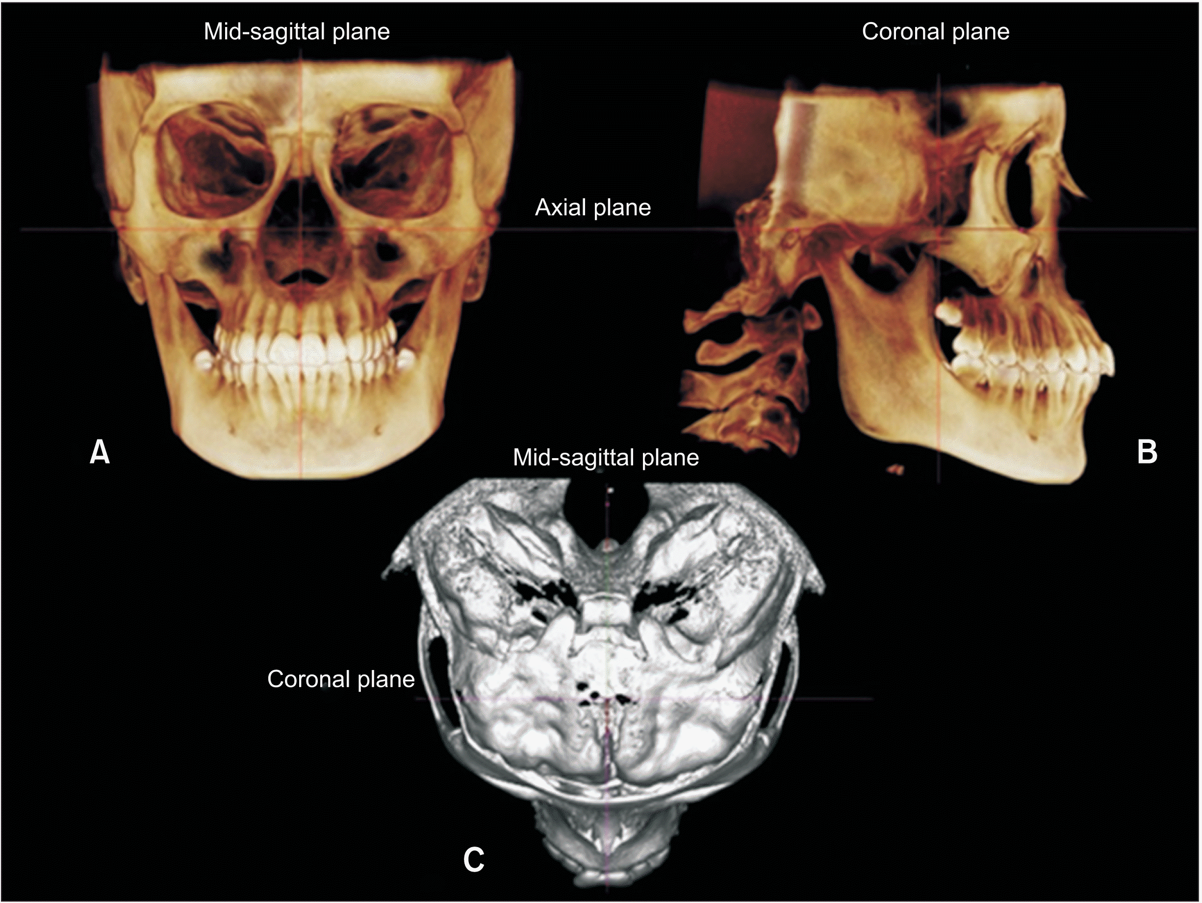
The standardization of head position was performed in 3D images, specifically, in frontal view, the infraorbital line (line formed by the points located in the upper region of infraorbital foramen) was parallel to the bottom edge of the screen; in sagittal view, the Frankfurt horizontal plane (plane defined bilaterally by the right and left porions and right orbitale landmarks) was parallel to the bottom edge of the screen; finally, in axial view, the midsagittal line (center point in foramen magnum to point located on the crista galli) was perpendicular to the bottom edge of the screen (Figure 1).
Next, the apex of the distobuccal root of each permanent maxillary first molar was located, using a 3D sagittal view to obtain a coronal view on each side. Three measurements were obtained along the IZC. All of them were performed at an angle of 70 degrees to the occlusal plane.8 The first measurement was performed at 11 mm above the mesiobuccal cusp tip of the permanent right and left first molars, specifically, where the horizontal axis of the program coincided with the buccal surface of the IZC. The next two measurements were performed at 13 and 15 mm, using the same protocol as for the first measurement (11 mm)8 (Figure 2).
Before image selection for the MBS measurement, the head was standardized on sagittal view, according to the functional occlusal plane, which is a line joining the point bisecting the maxillary first molar (U6) occlusal and mandibular first molar (L6) occlusal with the midpoint bisecting the intercuspation of the first premolars, making it parallel to the floor.18 To meet the objectives of the present study, measurements were performed in the following mandibular buccal areas: Distal root projection of the mandibular first molar on the left and right sides (MBS 6d); mesial root projection of the mandibular second molar on both sides (MBS 7m); and distal root projection of the mandibular second molar on both sides (MBS 7d).
For each tooth, the image in the sagittal view was positioned, so the blue reference line was positioned at the cementoenamel junction (CEJ) of the evaluated tooth. Evaluation of the total buccal bone thickness was performed, based on two horizontal reference lines located apically at 4 mm and 8 mm from the CEJ in the apical direction, in coronal view, extending from the midpoint of the mesial and distal roots to the outer border of the adjacent alveolar bone cortical plate (Figure 3).
Twenty percent of the CBCT scan samples were randomly selected and re-evaluated 30 days after the first measurement. The systematic error was calculated by comparing the values of the first and second measurement, using a paired t-test with p-values of < 0.05 considered indicative of a statistically significant finding.19 The casual error was estimated, using Dahlberg’s formula (Se2 = Σd2/2n), where Se2 is the error variance and “d” is the difference between two determinations of the same variable.20
The normality of data distribution was examined, using the Kolmogorov–Smirnov test. One-way analysis of variance (ANOVA) was used to compare groups on age. The sex distribution among the groups was evaluated, using the chi-square test. Intergroup comparisons of CBCT findings were performed by one-way ANOVA and the Tukey tests. All statistical analyses were performed with Statistica software 7.0 (StatSoft, Inc., Tulsa, OK, USA). Findings were considered statistically significant at p-values of < 0.05.
Systematic and casual (Dahlberg’s formula) error estimates revealed no intra-examiner difference (Table 2). Sex distribution is presented in Table 3. Table 4 shows comparisons of the right and left sides among the brachyfacial, mesofacial, and dolichofacial groups. No statistically significant differences were observed between the right and left sides in any of the groups; thus, intergroup comparisons were performed.
No statistically significant differences in age or the IZC measurements were found among the groups (Table 5). However, the IZC measurements at 11 mm from the maxillary molar cusp tips presented larger values, while these values of cortical bone thickness decreased as the height of the miniscrew insertion increased (Figure 4). For the MBS measurements, the miniscrew insertion positions that presented statistically significant differences varied. The brachyfacial and dolichofacial groups presented greater cortical bone thickness values at the distal of the lower first molars at 8 mm from the CEJ and at 4 mm on the mesial aspect of the second molars. However, at the 4 mm level of the distal aspect of the second molars, the dolichofacial group presented larger values than did the other groups (Figure 5).
Based on previous studies,12-14 we expected to find significant differences among the placement sites, favoring the brachycephalic group; however, such differences were not observed in the present study in the IZC at any insertion height (Table 3).
A consensus in the field of orthodontics maintains that the skeletal architecture varies among facial types, for instance, that short-faced patients present with wider cortical plates and more medullary bone than do long-faced patients. This observation may hold, when the total area from the buccal cortical bone to the lingual cortical bone is measured. However, when the area of interest is restricted to the IZC (cortical bone + alveolar bone buccal to the roots), this consensus is not corroborated; this discrepancy may be due to methodological differences among studies; herein, we assessed bone availability at an angle of 70 degrees with the occlusal plane, which is relevant to clinical practice. In addition, in the present study, the available amount of bone (cortical plates plus medullary bone) for miniscrew placement decreased with an increase in the height of the insertion point. Specifically, an increase of 2 mm in insertion height translated to a decrease of approximately 2 mm in the available bone thickness (Table 3).
Regarding MBS measurements, our results show that the buccal alveolar bone thickness increased from the anterior to the posterior region and from the crest edge to the mandibular roots, corroborating the findings of Gandhi et al.14 and Liu et al.21 However, some differences were found among the facial groups evaluated. We expected that there would be differences between the more extreme facial types, favoring the short-faced subjects, as demonstrated in a recent study by Gandhi et al.14 However, both the short- and long-faced subjects presented similar conditions for placing an extra-alveolar miniscrew. In all six of the evaluated sites, mesocephalic subjects presented less bone than did the other two groups; three out of six evaluated sites showed statistically significant differences. At distal root of the first molar (MBS 6d 8 mm), for instance, brachycephalic and dolichocephalic subjects had at least 0.9 mm more bone width than did the mesofacial group. At the mesial aspect second molar region (MBS 7m 4 mm), dolichofacial subjects tended to present more bone than did the brachycephalic group, followed by the mesofacial group. Also, at MBS 7d 4 mm, the brachycephalic group presented with insertion area 0.9 mm greater than that in the other groups, where this area was comparable.
While three of the six MBS measuring sites showing smaller values for mesofacial group than either brachyfacial or dolichofacial, or both groups were unexpected, these differences were in the range of 0.9 to 1.47 mm, which, despite the statistical significance, may not be clinically meaningful. We expected that the brachycephalic individuals would present with larger values in both the IZC and MBS measurements, in particular, relative to those of the dolichocephalic group; however, the long-faced subjects presented with values similar to those of the short-faced group. One possible explanation for these results being different from those of Gandhi et al.14 may be the difference in the population strata used for sampling; however, these authors did not report the details of their sampling or measurement methodology.
Facial morphology varies between populations. This finding may be due to genetic variability among different groups. Many variations in cephalometric patterns have been observed even within ethnic groups worldwide.22 Brazil is a large, heterogenous country, where gene frequencies differ among sub-populations.23 One study24 evaluated genetic variations that affect muscle composition or properties related to muscle activity, and which could also affect the skeletal configuration; this study concluded that some genetic markers for facial sagittal and/or vertical alterations may vary among ethnic groups. For example, compared to Caucasian subjects, Brazilian Afro-Caucasian subjects present with greater maxillary protrusion, smaller upper anterior face height and lower posterior face height, larger upper posterior face height, greater maxillary and mandibular dentoalveolar protrusion as well as soft tissue protrusion.25 Moreover, a recent study26 compared White Brazilian, Japanese, and Japanese-Brazilian groups on the parameters of McNamara’s cephalometric analysis, concluding that cephalometric parameters differ among these groups and cannot be easily translated.
In addition, another recent study,27 evaluating a sample of Brazilian patients, found a statistically significant and inversely proportional correlation, both transversely and vertically, between bone thickness in the MBS and gonial angle. A reduced gonial angle is usually associated with short-faced patients; thus, it can be inferred that individuals with short vertical facial height present with greater bone thickness than do those with a long face; this finding was consistent with that of previous studies.11,12,28 Consequently, short-faced patients may be suitable candidates for the installation of miniscrews in the MBS due to the bone thickness permitting greater surgical perforations and the insertion of larger and longer miniscrews, which affect the primary stability of these devices.27
Overall, this evidence suggests that facial type may not be as good a predictor of adequate bone availability for extra alveolar miniscrew placement as it is generally assumed. As such, only CBCT imaging with adequate parameters can show bone availability and ideal location. While facial types may be related to the quality of the bone trabeculae and the total amount of bone, the evidence is insufficient to suggest that it may be used to indicate where extra-alveolar miniscrews should be placed. In the present study, although some differences were noted, specific locations seem to consistently present with the minimal required bone thickness for either IZC or MBS placement.
The present study had several limitations, which should be considered when interpreting its findings, including sample size, which was small, precluding the exclusion of patients with borderline facial types, thus reducing the relative distinctiveness of the groups. In addition, the CBCT unit and the protocol used involved a 0.30-mm voxel size. Smaller voxel dimensions may improve the discernment of cortical bone thickness.
The present study suggests that the skeletal facial pattern may influence but not determine, in a clinically meaningful way, the availability of bone for the insertion of extra-alveolar miniscrews at the MBS area. Dolichocephalic subjects tend to present with bone conditions similar or superior to those of brachycephalic individuals; both of these groups present with better conditions than does the mesocephalic group. Finally, the IZC cortical bone thickness was similar among the groups.
REFERENCES
1. Baumgaertel S. 2014; Temporary skeletal anchorage devices: the case for miniscrews. Am J Orthod Dentofacial Orthop. 145:558–64. DOI: 10.1016/j.ajodo.2014.03.009. PMID: 24785918.

2. Baumgaertel S. 2011; Cortical bone thickness and bone depth of the posterior palatal alveolar process for mini-implant insertion in adults. Am J Orthod Dentofacial Orthop. 140:806–11. DOI: 10.1016/j.ajodo.2011.05.020. PMID: 22133945.

3. Baumgaertel S, Hans MG. 2009; Buccal cortical bone thickness for mini-implant placement. Am J Orthod Dentofacial Orthop. 136:230–5. DOI: 10.1016/j.ajodo.2007.10.045. PMID: 19651353.

4. Gracco A, Lombardo L, Cozzani M, Siciliani G. 2008; Quantitative cone-beam computed tomography evaluation of palatal bone thickness for orthodontic miniscrew placement. Am J Orthod Dentofacial Orthop. 134:361–9. DOI: 10.1016/j.ajodo.2007.01.027. PMID: 18774082.

5. Baumgaertel S, Hans MG. 2009; Assessment of infrazygomatic bone depth for mini-screw insertion. Clin Oral Implants Res. 20:638–42. DOI: 10.1111/j.1600-0501.2008.01691.x. PMID: 19281501.

6. Chang C, Liu SS, Roberts WE. 2015; Primary failure rate for 1680 extra-alveolar mandibular buccal shelf mini-screws placed in movable mucosa or attached gingiva. Angle Orthod. 85:905–10. DOI: 10.2319/092714.695.1. PMID: 25603272.

7. Nucera R, Lo Giudice A, Bellocchio AM, Spinuzza P, Caprioglio A, Perillo L, et al. 2017; Bone and cortical bone thickness of mandibular buccal shelf for mini-screw insertion in adults. Angle Orthod. 87:745–51. DOI: 10.2319/011117-34.1. PMID: 28598220. PMCID: PMC8357207.

8. Liou EJ, Chen PH, Wang YC, Lin JC. 2007; A computed tomographic image study on the thickness of the infrazygomatic crest of the maxilla and its clinical implications for miniscrew insertion. Am J Orthod Dentofacial Orthop. 131:352–6. DOI: 10.1016/j.ajodo.2005.04.044. PMID: 17346590.

9. Chang C, Huang C, Roberts WE. 2016; 3D cortical bone anatomy of the mandibular buccal shelf: a CBCT study to define sites for extra-alveolar bone screws to treat Class III malocclusion. Int J Orthod Implantol. 41:74–82.
10. Elshebiny T, Palomo JM, Baumgaertel S. 2018; Anatomic assessment of the mandibular buccal shelf for miniscrew insertion in white patients. Am J Orthod Dentofacial Orthop. 153:505–11. DOI: 10.1016/j.ajodo.2017.08.014. PMID: 29602342.

11. Tsunori M, Mashita M, Kasai K. 1998; Relationship between facial types and tooth and bone characteristics of the mandible obtained by CT scanning. Angle Orthod. 68:557–62. DOI: 10.1043/0003-3219(1998)068<0557:RBFTAT>2.3.CO;2. PMID: 9851354.
12. Ozdemir F, Tozlu M, Germec-Cakan D. 2013; Cortical bone thickness of the alveolar process measured with cone-beam computed tomography in patients with different facial types. Am J Orthod Dentofacial Orthop. 143:190–6. DOI: 10.1016/j.ajodo.2012.09.013. PMID: 23374925.

13. Sadek MM, Sabet NE, Hassan IT. 2015; Alveolar bone mapping in subjects with different vertical facial dimensions. Eur J Orthod. 37:194–201. DOI: 10.1093/ejo/cju034. PMID: 25114124.

14. Gandhi V, Upadhyay M, Tadinada A, Yadav S. 2021; Variability associated with mandibular buccal shelf area width and height in subjects with different growth pattern, sex, and growth status. Am J Orthod Dentofacial Orthop. 159:59–70. DOI: 10.1016/j.ajodo.2019.11.020. PMID: 33221093.

15. Murugesan A, Sivakumar A. 2020; Comparison of bone thickness in infrazygomatic crest area at various miniscrew insertion angles in Dravidian population - a cone beam computed tomography study. Int Orthod. 18:105–14. DOI: 10.1016/j.ortho.2019.12.001. PMID: 31926867.
16. Ricketts RM. 1961; Cephalometric analysis and synthesis. Angle Orthod. 31:141–56.
17. Neves LS, Pinzan A, Janson G, Canuto CE, de Freitas MR, Cançado RH. 2005; Comparative study of the maturation of permanent teeth in subjects with vertical and horizontal growth patterns. Am J Orthod Dentofacial Orthop. 128:619–23. DOI: 10.1016/j.ajodo.2004.05.026. PMID: 16286209.

18. Li JL, Kau C, Wang M. 2014; Changes of occlusal plane inclination after orthodontic treatment in different dentoskeletal frames. Prog Orthod. 15:41. DOI: 10.1186/s40510-014-0041-1. PMID: 25033937. PMCID: PMC4884032.

19. Houston WJ. 1983; The analysis of errors in orthodontic measurements. Am J Orthod. 83:382–90. DOI: 10.1016/0002-9416(83)90322-6. PMID: 6573846.

20. Dahlberg G. 1940. Statistical methods for medical and biological students. Allen & Unwin;London:
21. Liu H, Wu X, Yang L, Ding Y. 2017; Safe zones for miniscrews in maxillary dentition distalization assessed with cone-beam computed tomography. Am J Orthod Dentofacial Orthop. 151:500–6. DOI: 10.1016/j.ajodo.2016.07.021. PMID: 28257734.

22. de Freitas LM, de Freitas KM, Pinzan A, Janson G, de Freitas MR. 2010; A comparison of skeletal, dentoalveolar and soft tissue characteristics in white and black Brazilian subjects. J Appl Oral Sci. 18:135–42. DOI: 10.1590/S1678-77572010000200007. PMID: 20485924. PMCID: PMC5349749.
23. Castilla EE, Luquetti DV. 2009; Brazil: public health genomics. Public Health Genomics. 12:53–8. DOI: 10.1159/000153424. PMID: 19023184.

24. Cunha A, Nelson-Filho P, Marañón-Vásquez GA, Ramos AGC, Dantas B, Sebastiani AM, et al. 2019; Genetic variants in ACTN3 and MYO1H are associated with sagittal and vertical craniofacial skeletal patterns. Arch Oral Biol. 97:85–90. DOI: 10.1016/j.archoralbio.2018.09.018. PMID: 30366217.

25. Janson G, Quaglio CL, Pinzan A, Franco EJ, de Freitas MR. 2011; Craniofacial characteristics of Caucasian and Afro-Caucasian Brazilian subjects with normal occlusion. J Appl Oral Sci. 19:118–24. DOI: 10.1590/S1678-77572011000200007. PMID: 21552712. PMCID: PMC4243749.

26. Storniolo-Souza JM, Seminario MP, Pinzan-Vercelino CRM, Pinzan A, Janson G. 2021; McNamara analysis cephalometric parameters in White-Brazilians, Japanese and Japanese-Brazilians with normal occlusion. Dental Press J Orthod. 26:e2119133. DOI: 10.1590/2177-6709.26.1.e2119133.oar. PMID: 33759961. PMCID: PMC8018756.

27. Vargas EOA, Lopes de Lima R, Nojima LI. 2020; Mandibular buccal shelf and infrazygomatic crest thicknesses in patients with different vertical facial heights. Am J Orthod Dentofacial Orthop. 158:349–56. DOI: 10.1016/j.ajodo.2019.08.016. PMID: 32862936.
28. Masumoto T, Hayashi I, Kawamura A, Tanaka K, Kasai K. 2001; Relationships among facial type, buccolingual molar inclination, and cortical bone thickness of the mandible. Eur J Orthod. 23:15–23. DOI: 10.1093/ejo/23.1.15. PMID: 11296507.

Figure 2
A, Coronal slice consisting of the apex of the distobuccal root of the permanent first maxillary molar. B-D, Measurement of infrazygomatic crest thickness, performed at 11 mm above the buccal tip of the right first maxillary molar at an angle of 70 degrees to the occlusal plane.
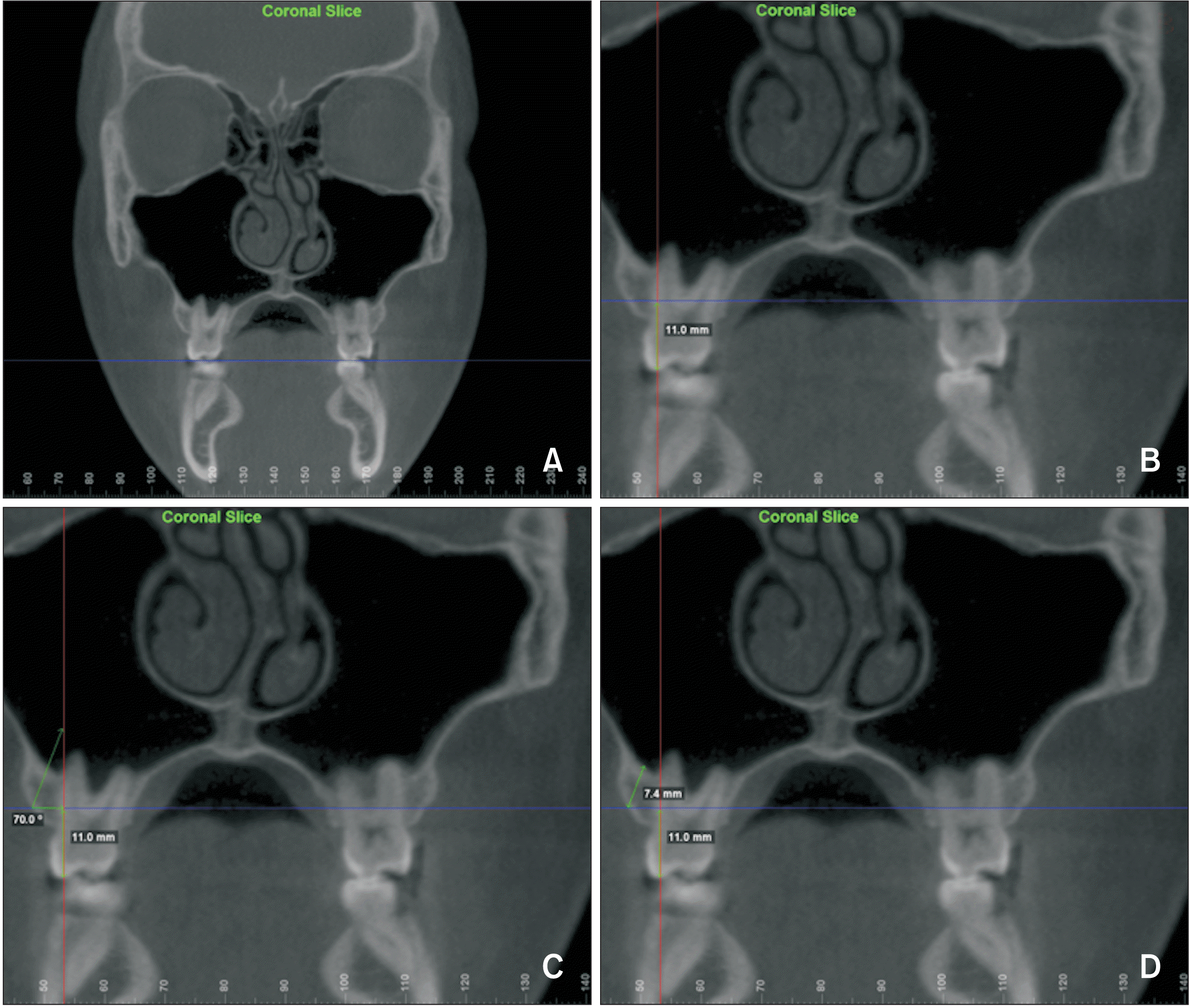
Figure 3
Bucco-lingual thicknesses of total bone measured on two horizontal reference lines apically located at 4 mm and 8 mm from the cementoenamel junction.
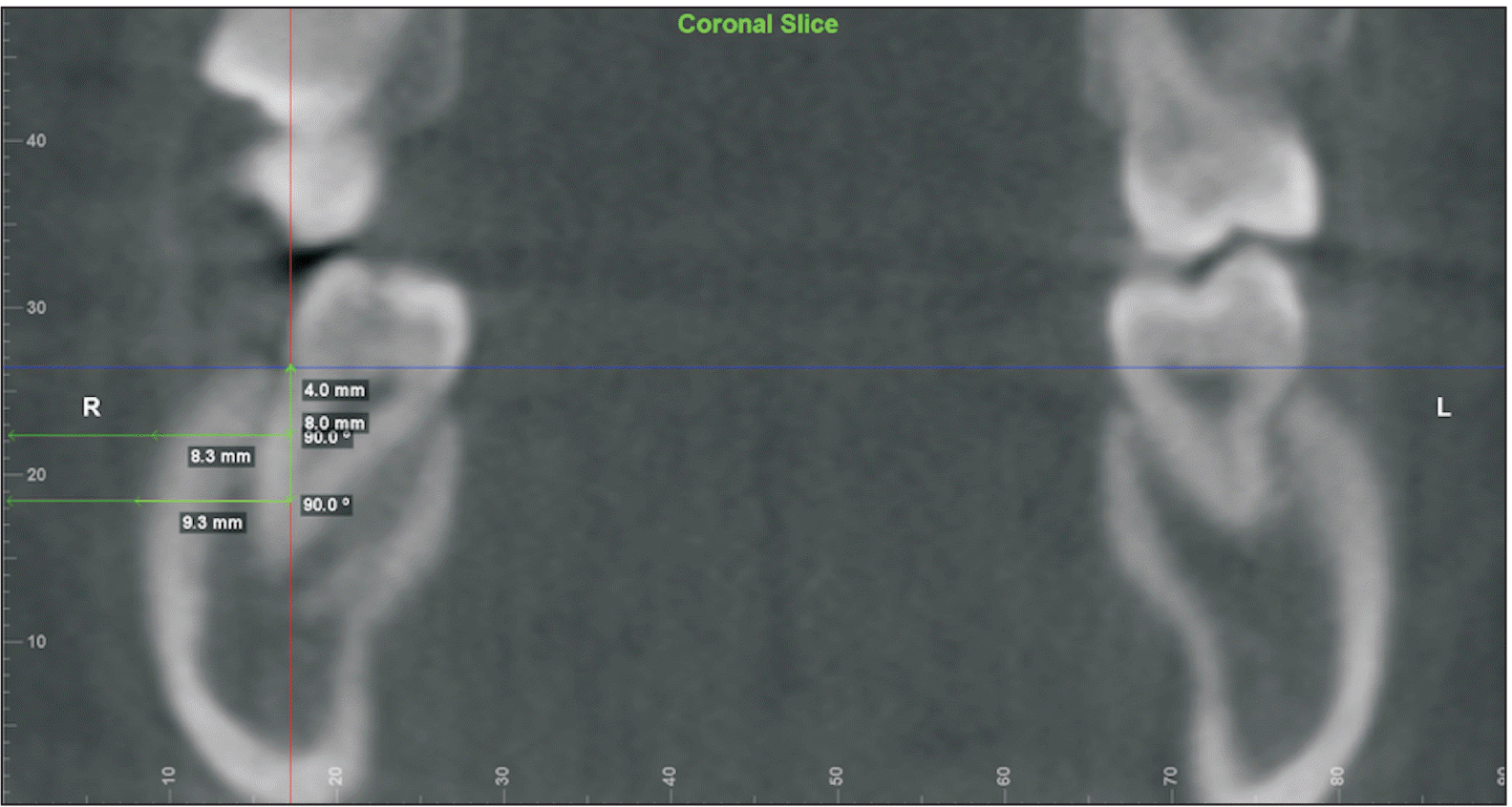
Figure 4
Color based diagram showing infrazygomatic crest (IZC) areas of adequate cortical bone thickness.
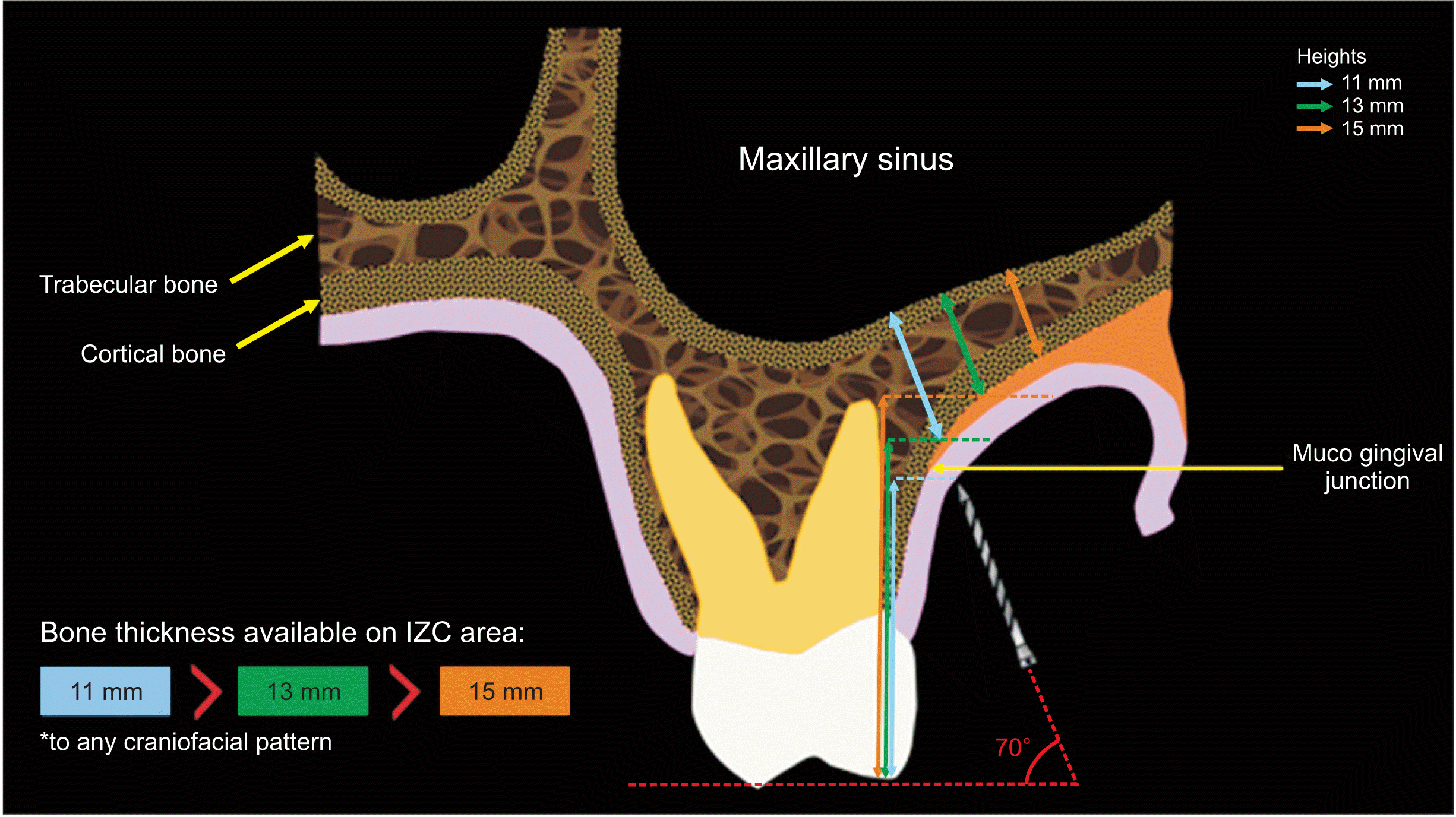
Figure 5
A, Bone thickness for different craniofacial patterns at MBS 6d. B, Bone thickness for different craniofacial patterns at MBS 7m. C, Bone thickness for different craniofacial patterns at MBS 7d.
MBS, mandibular buccal shelf; 6, first molar; 7, second molar; m, mesial; d, distal; (+), (++), (+++), amount of cortical bone available in mandibular buccal shelf.
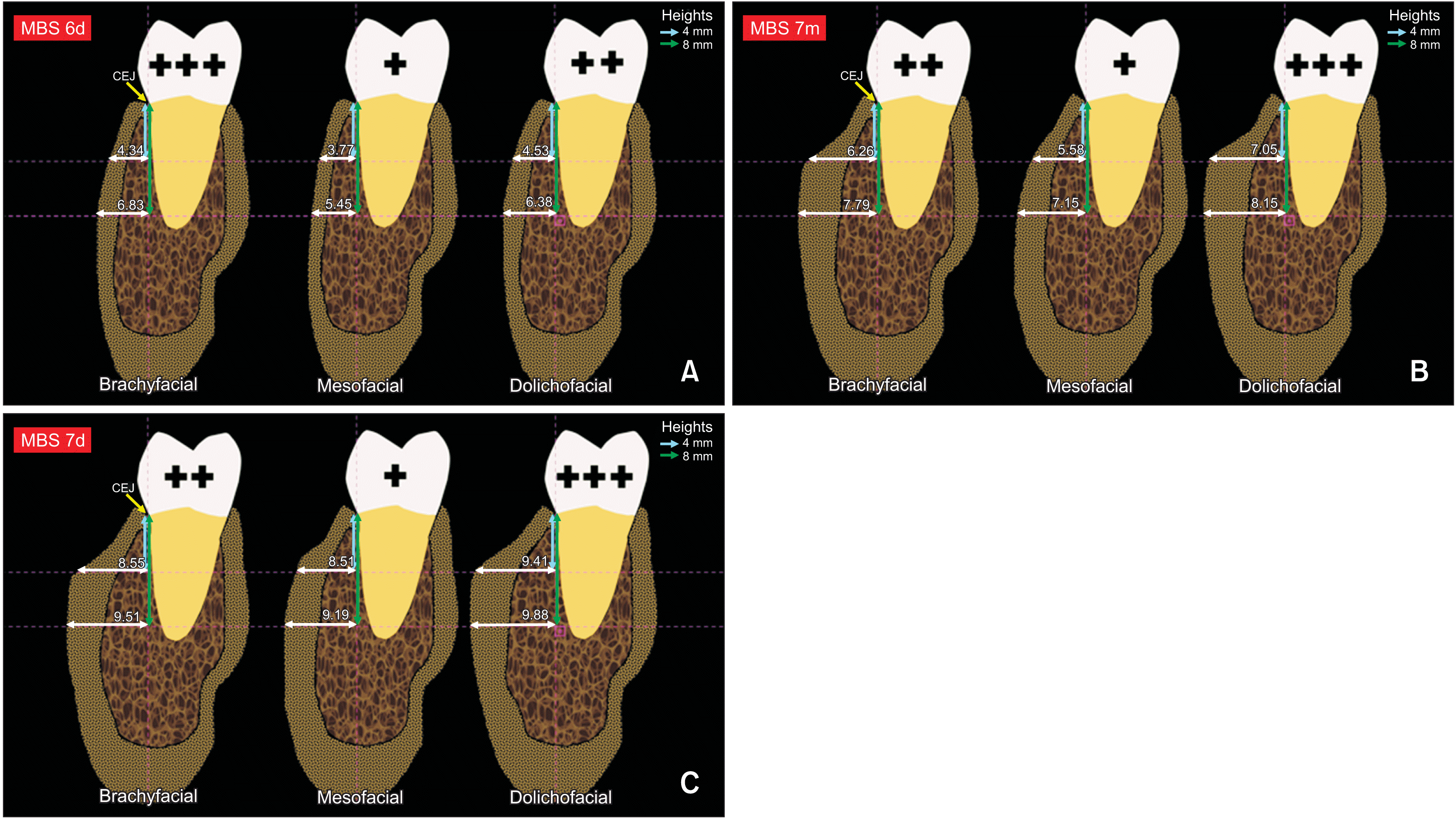
Table 1
Ricketts VERT analysis findings for experimental groups
| Craniofacial patterns | VERT index | |
|---|---|---|
| Mean | Standard deviation | |
| Brachyfacial | 1.51 | 0.141 |
| Mesofacial | −0.10 | 0.494 |
| Dolichofacial | −1.52 | 0.636 |
Table 2
Results of error study (unit, mm)
Table 3
Intergroup comparison of sex distribution in different vertical craniofacial patterns
| Group | Male | Female | Total | X2 | DF | p-value |
|---|---|---|---|---|---|---|
| Brachyfacial | 7 | 8 | 15 | 0.18 | 2 | 0.913 |
| Mesofacial | 6 | 9 | 15 | |||
| Dolichofacial | 7 | 8 | 15 | |||
| Total | 20 | 25 | 45 |
Table 4
Comparisons of the right and left sides in the brachyfacial, mesofacial, and dolichofacial groups (unit, mm)
Table 5
Comparisons of bone thickness (IZC and MBS) among different vertical craniofacial patterns
| Variable | Brachyfacial (n = 30) | Mesofacial (n = 30) | Dolichofacial (n = 30) | p-value |
|---|---|---|---|---|
| Age (yr) | 22.20 ± 7.40 | 19.24 ± 5.92 | 17.79 ± 3.63 | 0.122 |
| IZC 11 (mm) | 9.33 ± 2.27 | 8.82 ± 1.83 | 8.87 ± 1.91 | 0.565 |
| IZC 13 (mm) | 7.51 ± 2.16 | 7.16 ± 1.93 | 7.11 ± 1.95 | 0.712 |
| IZC 15 (mm) | 5.94 ± 2.15 | 5.59 ± 1.88 | 5.39 ± 1.86 | 0.561 |
| MBS 6d 4 (mm) | 4.34 ± 1.44 | 3.77 ± 1.51 | 4.53 ± 1.33 | 0.131 |
| MBS 6d 8 (mm) | 6.83 ± 1.76A | 5.45 ± 1.94B | 6.38 ± 1.67A | 0.017* |
| MBS 7m 4 (mm) | 6.26 ± 2.13AB | 5.58 ± 1.96A | 7.05 ± 1.42B | 0.015* |
| MBS 7m 8 (mm) | 7.79 ± 1.97 | 7.15 ± 1.45 | 8.15 ± 1.45 | 0.082 |
| MBS 7d 4 (mm) | 8.55 ± 1.84A | 8.51 ± 1.29A | 9.41 ± 1.31B | 0.042* |
| MBS 7d 8 (mm) | 9.51 ± 1.54 | 9.19 ± 1.13 | 9.88 ± 1.37 | 0.171 |
IZC, infrazygomatic crest; MBS, mandibular buccal shelf; 6, the mandibular first molar; 7, the mandibular second molar; d, distal root projection; m, mesial root projection.


 PDF
PDF Citation
 Print
Print


 XML Download