

 PDF
PDF Citation
 Print
Print


INTRODUCTION
The accuracy of digital impressions obtained using intraoral scanners for a single tooth is equivalent or even superior to that of conventional impressions.1-3 However, the dimensional accuracy of full-arch intraoral scan data acquired using an intraoral scanner, relative to the accuracy of conventional impressions, remains controversial.1,4,5
Because of the limited field of view provided by intraoral scanners, several small, three-dimensional (3D) scan data are acquired and superimposed to create the final 3D surface data. However, errors may occur during the process of integrating the numerous acquired images. When larger objects are scanned, the amount of error may increase because a larger number of raw images need to be processed, which results in dimensional inaccuracies. A full-arch scan starts from the most distal molar and ends at the most distal molar on the contralateral side; therefore, errors in superimposition accumulate, leading to deformation of the arch shape and errors in the arch dimensions, particularly in the molar region.6-8 The dark and humid oral cavity with anatomic structures such as the tongue and buccal mucosa also contribute to inaccuracies in the scan data.9
Many studies have evaluated the accuracy of full-arch scans obtained using intraoral scanners, although most have conducted in vitro evaluations using dental casts. Errors in intraoral scan data may be greater when a patient is scanned than when a dental cast is scanned, considering the transparency of natural teeth and optical reflections as well as the humid intraoral environment.10 Only a few studies have evaluated full-arch scans acquired directly in a patient’s oral cavity.11 Acquisition of an accurate reference data set for in vivo analysis of trueness is difficult because dental arches cannot be scanned with tactile or other high-precision optical laboratory scanners. Previous in vivo studies used gypsum casts obtained from conventional impressions as a reference or only measured the precision of intraoral scan data.12-14 The dimensional accuracy of full-arch scans obtained using industrial scanners is reportedly higher than that of conventional impressions.15 Therefore, it may be used as a reference for measuring the precision and trueness of full-arch impressions. In one study, the researchers obtained a direct scan of the teeth using an industrial-grade scanner to derive reference data for analyzing trueness; however, only the incisors and premolars could be captured.16
Accordingly, the purpose of this study was to evaluate the in vivo trueness and precision of full-arch scans acquired using five intraoral scanners and an industrial-grade scanner for reference scans. In addition, we aimed to compare the trueness and precision of intra-arch linear dimensions across the canines and molars. The null hypothesis was that there are no differences in the trueness and precision of full-arch scan data among different intraoral scanners.
MATERIALS AND METHODS
This prospective clinical study was approved by the Institutional Review Board of the Korea University Anam Hospital (2019AN0195). Nine healthy participants with a complete permanent dentition were recruited, and all of them provided written informed consent for participation in the study. The inclusion criteria were as follows: (1) age ≥ 19 years; (2) complete permanent dentition with healthy periodontium; and (3) healthy general condition that would facilitate cooperation during multiple intraoral scanning procedures. The exclusion criteria were as follows: (1) missing permanent teeth, excluding third molars; (2) two or more prostheses; (3) mouth opening < 35 mm; (4) symptoms of temporomandibular joint disorders; (4) crowding > 7 mm; and (5) asymmetry in the arch form.
The American National Standard Institute/American Dental Association Standard (ANSI/ADA) No. 132 for the scanning accuracy of dental chairside and laboratory computer-aided design/computer-aided manufacturing systems was employed for analysis of trueness and precision. Following random selection of either the maxillary (n = 6) or the mandibular arch (n = 3), zirconium spheres (Ø 6 mm; SBB Tech Co., Gimpo, Korea) were bonded, using flowable composite resin (FiltekTM Z350 XT; 3M Co., St. Paul, MN, USA), to the lingual or palatal surface of the right and left canines and the occlusal surface of the right and left first molars in the selected arch. The four spheres were references for the measurement of linear distances (Figure 1).
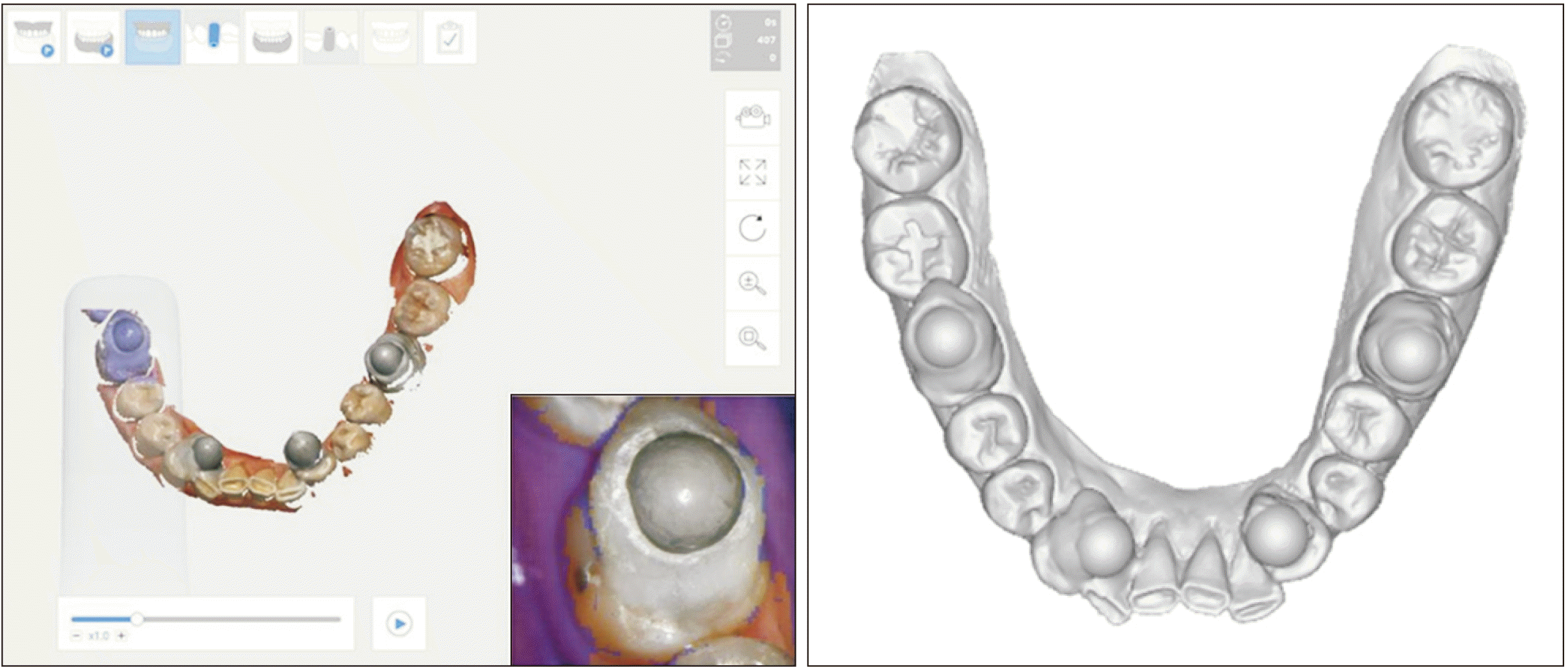
Figure 1
Placement of reference spheres for the in vivo measurement of linear distances. Four reference spheres have been attached to the lingual or palatal surface of the right and left canines and the occlusal surface of the right and left first molars. Intraoral scan data are acquired for accuracy analysis.
![]()
An industrial-grade scanner, Solutionix C500 (Medit Corp., Seoul, Korea; Table 1), was used to acquire scans of the four reference spheres. Following calibration of the scanner, each participant was positioned in the dental chair. Then, an intraoral retractor, Optragate (Ivoclar Vivadent, Schaan, Liechtenstein), was placed, the Solutionix C500 scanner was mounted on a tripod, and the four reference spheres placed in the participant’s dental arches were scanned with maximum mouth opening (Figure 2).
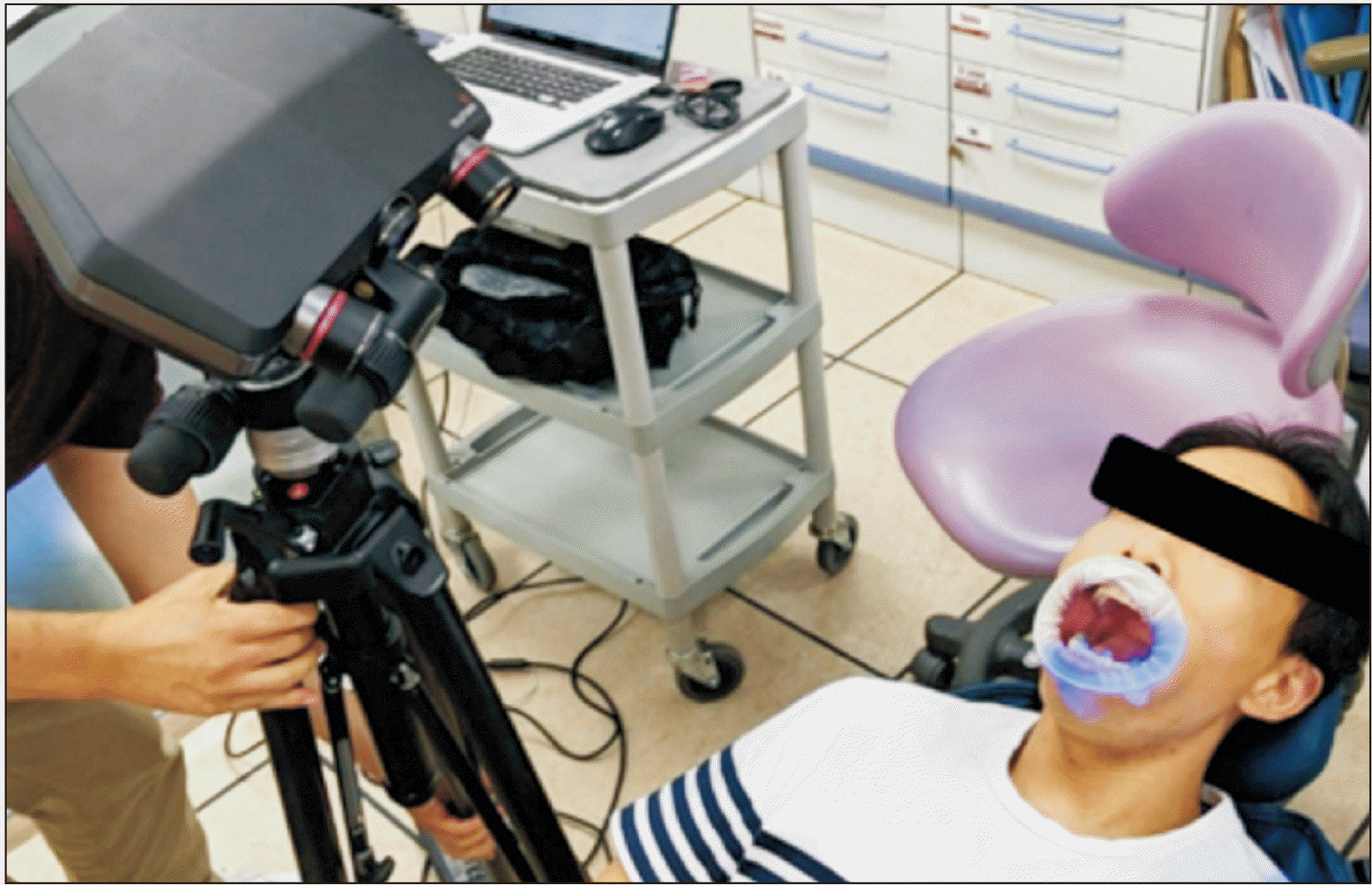
Figure 2
Reference scans for in vivo analysis of trueness. Reference scans of the four spheres are acquired using an industrial-grade scanner (Solutionix C500; Medit Corp., Seoul, Korea) for in vivo analysis of trueness.
![]()
Table 1
Specifications of the reference scanner (Solutionix C500; Medit Corp., Seoul, Korea) used in the study
![]()
Five commercially available intraoral scanners were used to scan the arches: i500 (Medit Corp.), CS3600 (Carestream Health, Rochester, NY, USA), Trios 3 (3Shape A/S, Copenhagen, Denmark), iTero (Align Technology, Inc., San Jose, CA, USA), and CEREC Omnicam (Dentsply Sirona, York, PA, USA) (Table 2). After calibration, five scans were obtained with each type of scanner for each participant, resulting in 25 scans per participant. To facilitate the scan process, three trained practitioners (M.K., M.S.K., and D.W.K.) acquired the intraoral scans using the continuous method, starting from the right molar. The intraoral and reference scans for each participant were obtained in the same visit, and subsequently, the reference spheres were removed. Scans of all participants were obtained over 2 days, and the scanners were calibrated at the beginning of each experimental day. The scan data were saved and exported in the standard tessellation language file format for analysis.
Table 2
Specifications of the intraoral scanners used in the study
![]()
Geomagic Control X software (version 2018.1.1; Evatronix SA, Bielsko-Biala, Poland) was used to measure the linear distances between the four reference spheres. The software automatically identifies and calculates the distance between the centers of the reference spheres by matching with pre-imputed specification data. After reorientation of the dental arches with the incisors facing up in the occlusal view, the spheres were numbered from 1 to 4 in a counterclockwise direction starting from the right lower sphere (Figure 3). Linear measurements were recorded as follows: distance 1 (between reference spheres 1 and 2), distance 2 (between reference spheres 1 and 3), distance 3 (between reference spheres 1 and 4), distance 4 (between reference spheres 2 and 3), distance 5 (between reference spheres 2 and 4), and distance 6 (between reference spheres 3 and 4; Figure 3).
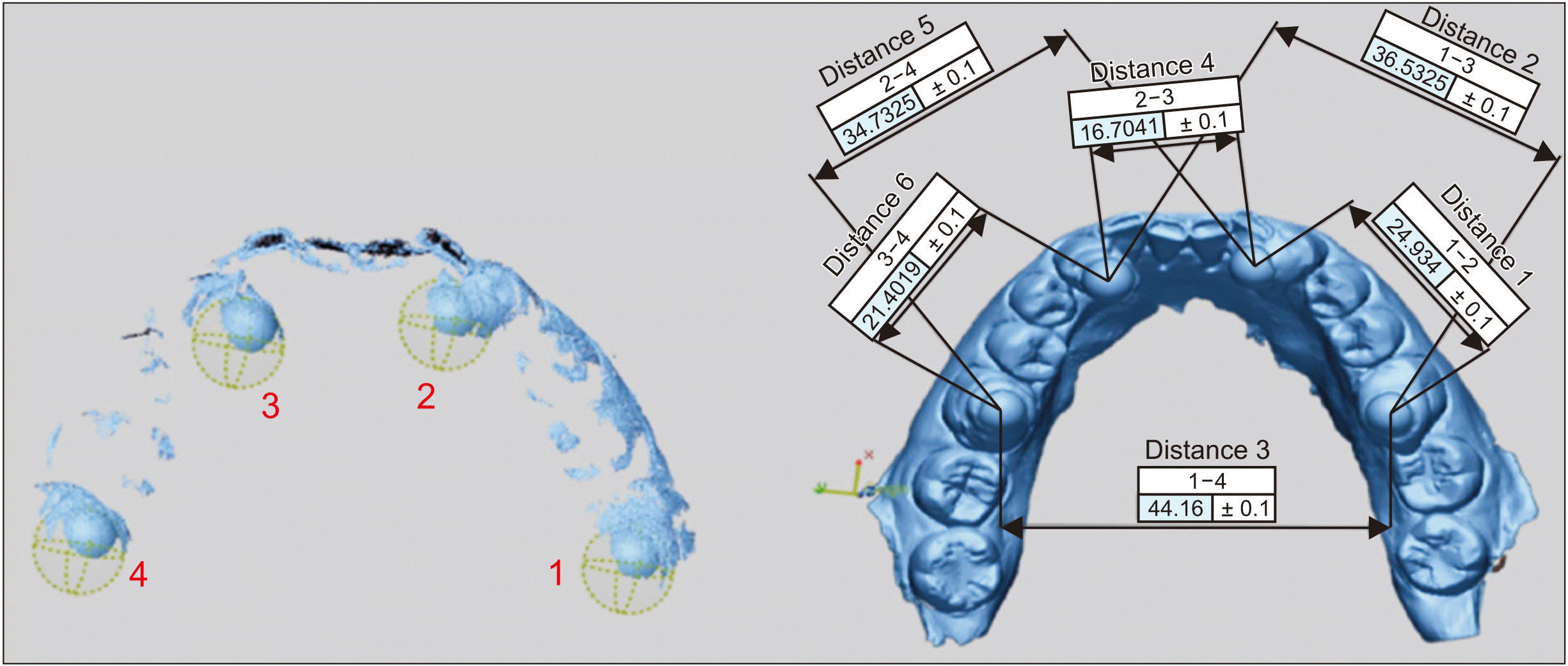
Figure 3
Measurement of linear distances. Linear distances between spheres are automatically calculated by matching with pre-imputed specification data.
Distance 1, between reference spheres 1 and 2; Distance 2, between reference spheres 1 and 3; Distance 3, between reference spheres 1 and 4; Distance 4, between reference spheres 2 and 3; Distance 5, between reference spheres 2 and 4; Distance 6, between reference spheres 3 and 4.
![]()
The linear distances measured from the reference scan was used as true reference data. The scanning accuracy of the Solutionix C500 is reported as 7–10 µm, in accordance with the system acceptance test for the scanning accuracy of optical 3D measuring systems (VDI/VDE 2634 Part 2 and 3). Trueness was evaluated by analyzing the differences in measured distances between the intraoral and reference scans. Precision was evaluated by analyzing the differences between different pairs of repeated intraoral scan data for the same participant, with 10 measurements per distance per participant.
Statistical analysis
Descriptive statistics of the trueness and precision of the linear measurements derived from the intraoral scans were obtained. Using the absolute errors, linear mixed model analysis was performed to compare the trueness and precision of the intraoral scanners according to the linear distances. Additional factors such as the practitioner who performed scanning and the arch (upper vs. lower) were considered possible confounding factors, and the significance of their effects was analyzed in the type III test. Through the F test, the feasibility of each statistical model with significant factors was evaluated. The Tukey–Kramer test was performed for post hoc analysis. All statistical analyses were performed using SAS software version 9.4 (SAS Institute, Cary, NC, USA). A p-value of < 0.05 was considered statistically significant.
RESULTS
The study sample comprised one woman and eight men with a mean age of 34.3 ± 8.3 years. One participant dropped out after scanning with two scanners (iTero and Omnicam) citing personal reasons.
The boxplots of mean negative, mean positive, and mean absolute errors in terms of trueness are shown in Figures 4 and 5. The absolute mean trueness and precision values for all intraoral scanners were 76.6 ± 79.3 and 56.6 ± 52.4 µm, respectively (Tables 3 and 4). Omnicam showed the greatest error in terms of trueness, followed by i500, CS3600, iTero, and Trios 3 (Table 3), while CS3600 showed the greatest error in terms of precision, followed by Omnicam, i500, iTero, and Trios 3 (Table 4). Distance 3 showed the greatest error in terms of trueness, followed by distances 5, 2, 4, 1, and 6. Distance 3 also showed the greatest error in terms of precision, followed by distances 2, 5, 4, 6, and 1 (Tables 3 and 4, Figure 6).
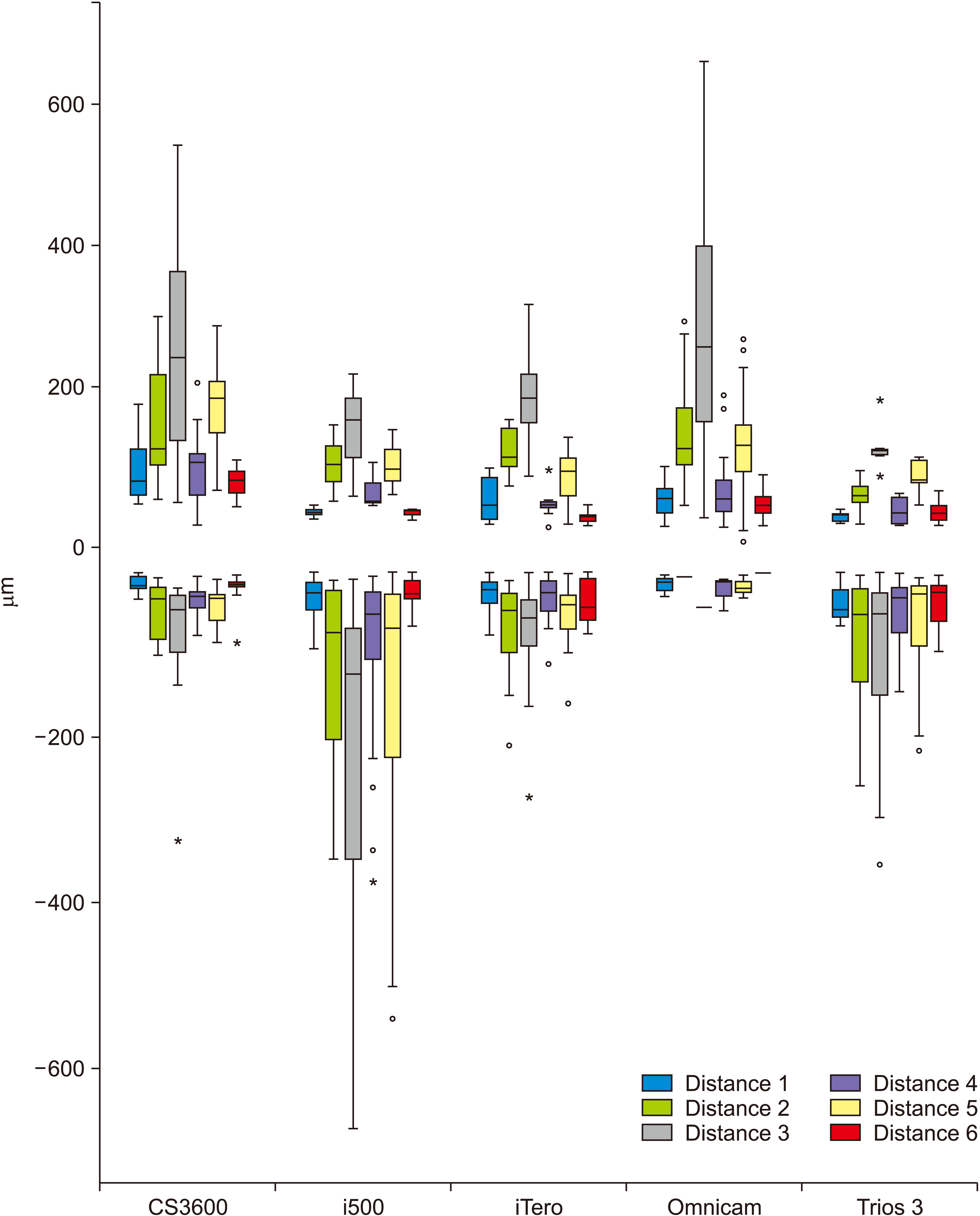
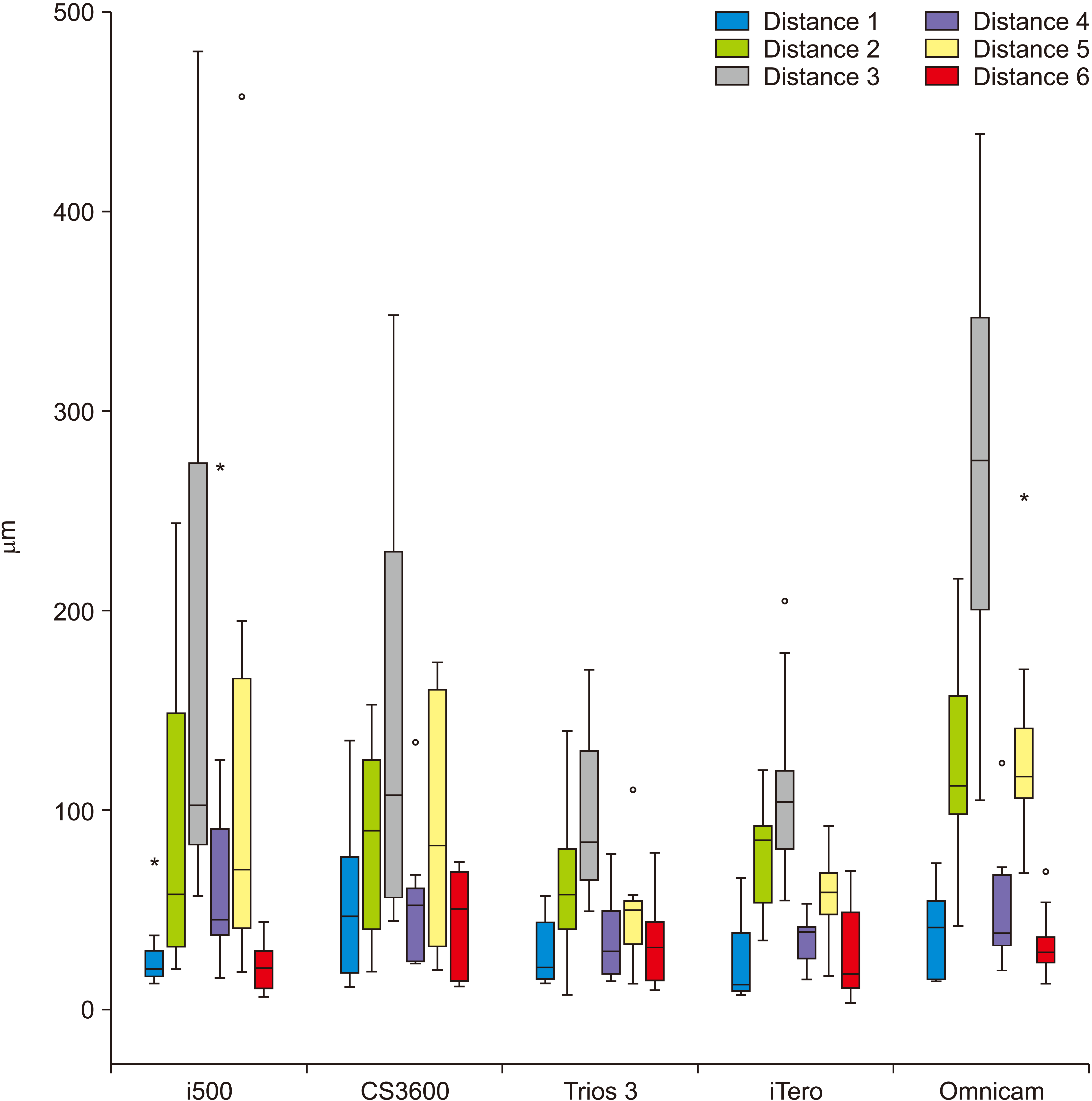
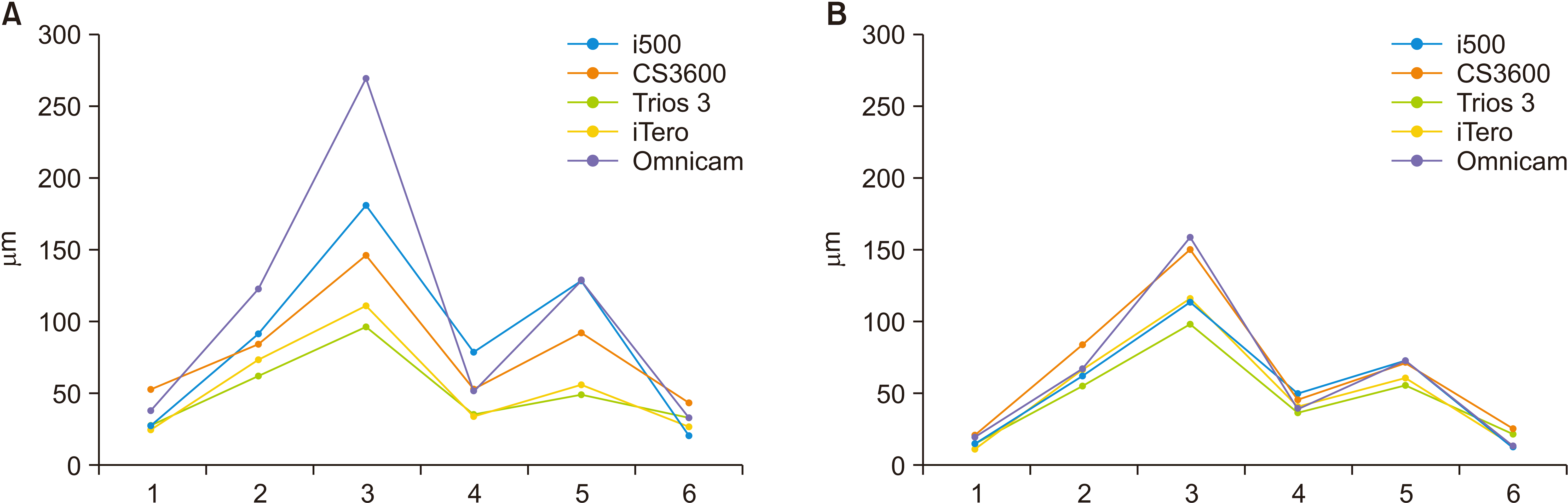
Figure 4
Mean positive and negative errors in terms of trueness according to the scanner type (µm).
Distance 1, between reference spheres 1 and 2; Distance 2, between reference spheres 1 and 3; Distance 3, between reference spheres 1 and 4; Distance 4, between reference spheres 2 and 3; Distance 5, between reference spheres 2 and 4; Distance 6, between reference spheres 3 and 4.
![]()
Figure 5
Mean absolute error in trueness according to the scanner type (µm).
Distance 1, between reference spheres 1 and 2; Distance 2, between reference spheres 1 and 3; Distance 3, between reference spheres 1 and 4; Distance 4, between reference spheres 2 and 3; Distance 5, between reference spheres 2 and 4; Distance 6, between reference spheres 3 and 4.
![]()
Figure 6
Mean absolute errors in terms of the trueness (A) and precision (B) of intraoral scanners according to the measured linear distances (µm).
1, distance between reference spheres 1 and 2; 2, distance between reference spheres 1 and 3; 3 distance between reference spheres 1 and 4; 4, distance between reference spheres 2 and 3; 5, distance between reference spheres 2 and 4; 6, distance between reference spheres 3 and 4.
![]()
Table 3
Trueness of linear dimensions measured from intraoral scan data (µm)
![]()
Table 4
Precision of linear dimensions measured from intraoral scan data (µm)
![]()
Linear mixed model analysis revealed significant differences in trueness (p = 0.009) and precision (p = 0.017) of some of the measured distances among the five scanners. With regard to trueness, there were significant differences among scanners in distances 3 and 5 (p = 0.023 and p = 0.021, respectively; Supplementary Table 1). With regard to precision, there were significant differences among scanners in distances 1 and 6 (p = 0.026 and p = 0.005, respectively; Supplementary Table 1). Other factors such as the practitioner who performed scanning and the arch (upper vs. lower) had no significant effect on the accuracy of the scan data.
According to the post hoc analysis of trueness, Omnicam showed a significantly greater error than Trios 3 for distances 3 (p = 0.023) and 5 (p = 0.017; Table 5); the other scanners showed no significant differences. With regard to precision, Omnicam and CS3600 showed significantly greater errors than iTero for distance 1 (p = 0.038 and p = 0.042, respectively; Table 6). For distance 6, the precision error was significantly greater with CS3600 than with Omnicam (p = 0.021), iTero (p = 0.047), and i500 (p = 0.042; Table 6).
Table 5
Pairwise comparisons of trueness among scanners for distances 3 (between reference spheres 1 and 4) and 5 (between reference spheres 2 and 4)
| Scanners | Distance 3 | Distance 5 | ||||
|---|---|---|---|---|---|---|
|
|
|
|||||
| Estimated difference (A–B) in trueness (µm) | p-value | Estimated difference (A–B) in trueness (µm) | p-value | |||
| A | B | |||||
| Omnicam | CS3600 | 800 | 0.130 | 590 | 0.413 | |
| Omnicam | iTero | 880 | 0.061 | 850 | 0.079 | |
| Omnicam | Trios 3 | 1,030* | 0.023 | 1,060* | 0.017 | |
| Omnicam | i500 | 580 | 0.427 | 410 | 0.747 | |
| CS3600 | iTero | 80 | 0.999 | 260 | 0.941 | |
| CS3600 | Trios 3 | 230 | 0.967 | 470 | 0.656 | |
| CS3600 | i500 | –220 | 0.970 | –180 | 0.986 | |
| iTero | Trios 3 | 150 | 0.993 | 220 | 0.970 | |
| iTero | ii500 | –300 | 0.903 | –440 | 0.695 | |
| Trios 3 | i500 | –450 | 0.705 | –650 | 0.336 | |
![]()
Table 6
Pairwise comparisons of precision among scanners for distances 1 (between reference spheres 1 and 2) and 6 (between reference spheres 3 and 4)
| Scanners | Distance 1 | Distance 6 | ||||
|---|---|---|---|---|---|---|
|
|
|
|||||
| Estimated difference (A–B) in precision (µm) | p-value | Estimated difference(A–B) in precision (µm) | p-value | |||
| A | B | |||||
| Omnicam | CS3600 | –10 | 0.999 | –723* | 0.021 | |
| Omnicam | iTero | 561* | 0.038 | –74 | 0.997 | |
| Omnicam | Trios 3 | 287 | 0.582 | –585 | 0.090 | |
| Omnicam | i500 | 276 | 0.619 | –43 | 0.999 | |
| CS3600 | iTero | 572* | 0.042 | 649* | 0.047 | |
| CS3600 | Trios 3 | 298 | 0.575 | 138 | 0.975 | |
| CS3600 | i500 | 286 | 0.611 | 680* | 0.042 | |
| iTero | Trios 3 | –274 | 0.624 | –512 | 0.175 | |
| iTero | i500 | –286 | 0.587 | 31 | 0.999 | |
| Trios 3 | i500 | –11 | 0.999 | 543 | 0.153 | |
![]()
Supplementary data is available at https://doi.org/10.4041/kjod.2021.51.2.95.
DISCUSSION
In a previous systematic review, among 2,500 studies on the accuracy of intraoral scanners, only eight in vivo studies acquired full-arch scans of patients.11 From these eight studies, four only analyzed the precision of the intraoral scanner. In vivo analysis of the trueness of intraoral scanners has been challenging because it is difficult to obtain “true” reference data. The indirect method of scanning gypsum casts obtained from polyvinyl siloxane impressions involves potential errors attributed to the properties of the impression material and gypsum.12,13,17 Kuhr et al.6 placed four metal spheres on the dental arch by using a precise metal transfer aid with predetermined distances between the balls. However, there is a possibility of errors during the process of indirect bonding. In an in vitro study, an industrial scanner showed trueness and precision errors of 5.3 ± 1.1 and 1.6 ± 0.6 µm, respectively; these were smaller than the errors shown by conventional impressions and digital impressions.15 To the best of our knowledge, the first in vivo analysis of trueness using an industrial-grade scanner was reported by Nedelcu et al.,16 who could only capture the reference data for the incisors and premolars. In the present study, we were able to obtain scans of the first molars by attaching reference spheres to their occlusal surface and scanning with maximum mouth opening. As the industrial scanner, Solutionix C500, provides a field of view of 175 mm, the four reference spheres could be captured in the same frame (Figure 2).
We found significant differences in accuracy depending on the measured distances. As expected, the greatest error in terms of trueness and precision was observed in the intermolar distance, followed by the distance from the canine to the contralateral molar, the intercanine width, and the distance from the canine to the ipsilateral molar. Considering that the linear measurement made within the same quadrant is more accurate than the intercanine and intermolar distances, we could infer that a greater dimensional error occurs in the incisor area. Unlike molars and premolars, which have occlusal surfaces, incisors have sharp incisal edges, which makes it difficult to obtain a smooth scan of the incisor area. Manufacturers suggest hovering over the labial and lingual surfaces of the incisors during the scan procedure. Because the dental arch is V-shaped, scanning errors in the incisors either increase or decrease the transverse dimension of the dental arch; thus, the intermolar distance shows the greatest error. Oh et al.18 reported that the accuracy of scan data can be affected by the orientation of the scanner head. The authors suggested that 180° rotation of the scanner head should be avoided during scanning of the incisors. Another possible factor related to errors in the posterior area is that scanning of the posterior region requires more raw data to be captured than the anterior region.13 Moreover, the lighting conditions during the scan procedure show different effects on the accuracy according to the type of scanner.19
All scanners showed a large range of negative and positive dimensional errors for each measured distance. When compared with the reference data, oversized scans would have positive values while undersized scans would have negative values. If the absolute values were not taken, the positive and negative errors would add up to values closer to zero, thus underestimating the errors.
Significant differences in the trueness and precision of some of the measured distances were observed among scanners. With regard to trueness, significant differences were observed in the intermolar distance and the distance from the right canine to the left molar. With regard to precision, the distance from the canine to the molar in the same quadrant showed significant variations. Although the linear dimensions from the canine to molar within the same quadrant showed the highest precision among all measured distances, some scanners showed significant differences in performance. This significant difference in precision could be attributed to the low mean error in the linear distances measured in the same quadrant. Conversely, the precision of the transverse arch dimensions showed high mean errors with large standard deviations.
We found that Omnicam showed higher dimensional errors in terms of trueness than the other scanners in the intermolar dimension and the distance from the canine to the contralateral molar. Meanwhile, Omnicam and CS3600 showed greater errors in terms of precision than other scanners in the linear distance from the canine to molar in the same quadrant.
A limitation of this study was the small number of participants. Moreover, there were differences in trueness and precision among some scanners that showed borderline non-significance. A further study with a larger number of participants may lead to a better understanding of the factors associated with the accuracy of intraoral scanners. Finally, although the practitioner who performed the scanning had no significant effect, some practitioners were not familiar with certain types of intraoral scanners, which could have affected the dimensional errors.
CONCLUSION
In summary, with regard to trueness, Omnicam showed greater dimensional errors than the other scanners in the intermolar distance and the distance from the canine to the contralateral molar. With regard to precision, Omnicam and CS3600 showed greater errors than the other scanners in the linear distance from the canine to the molar in the same quadrant. Thus, the dimensional accuracy of intraoral scan data may differ significantly according to the type of scanner, with the amount of error in terms of trueness being clinically significant.
 XML Download