INTRODUCTION
In coil embolization of cerebral aneurysms, it is very important to guide microcatheters to the appropriate location in the aneurysm and stabilize them during procedures [
3,
6,
8]. To do this, the microcatheters should be properly shaped. Usually, shaping is performed using the steam-shaping method, considering the complex vascular and aneurysmal geometry in the three-dimensional (3D) images. Lee et al. also reported that tailored steam shaping of the microcatheter is vital to achieve good angiographic outcomes in 429 anterior communicating artery (ACoA) aneurysms series [
7]. However, this shaping currently depends completely on the doctor’s assumption, estimation, and experience. In other words, the operator should fully understand the complex vascular and aneurysmal geometry through 3D images and then shape the microcatheters following this geometry. In addition to the understanding of the complex vascular and aneurysmal geometry, the ideal path of microcatheter in blood vessels and aneurysm should be estimated. Since all these processes depend on appropriate estimation by the operators, they are, therefore, highly dependent on the experience and effort of such operators.
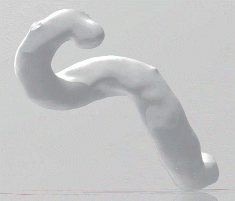
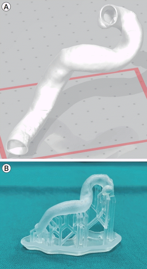
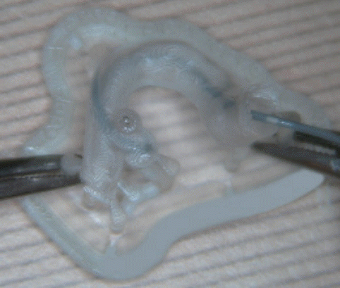
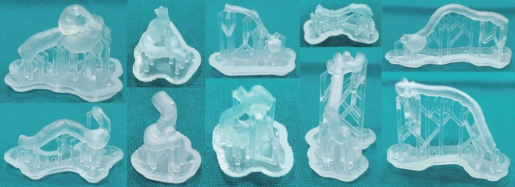
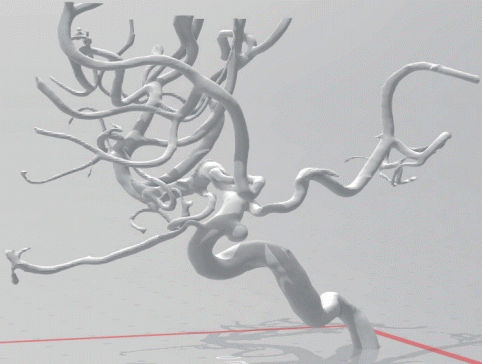
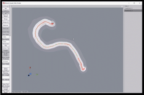
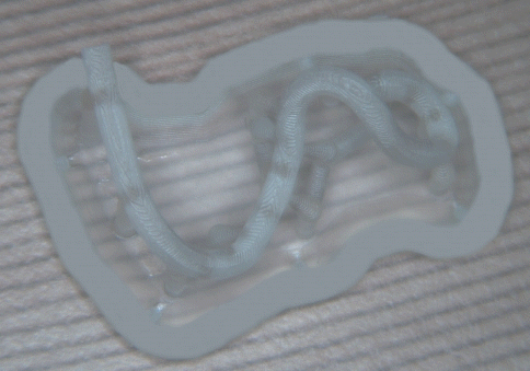
In this study, we carried out the shaping process of microcatheters using a computer application program (BVPF, Blood Vessel Path Finder; Kim’s laboratory, Kyeonggi-do, Korea) we developed and a three-dimensional printer (Form 2, Formlabs Inc., Somerville, MA, USA), without relying on the experiences and estimations of the operator. In addition, to confirm its feasibility, this microcatheter shaping method customized for patient-specific vessels, developed through this process, was applied to the 3D aneurysmal hollow model of the patients.
Go to :

RESULTS
In all 10 hollow models, the positioning of the microcatheter into the aneurysm was successful with one or two attempts. However, the aneurysmal hollow models were made from polymer (resin) using a 3D printer and a computer application program. Since the main purpose of the application program was not to fabricate the 3D hollow models, it was not perfect for the fabrication of the 3D hallow models. Thus, the luminal surfaces of the hollow models were rough. Unlike normal blood vessels, the 3D hollow models are hard, have no elasticity, and are very short. These factors made it difficult to advance or position the microcatheters into the aneurysms or even to maintain them once they are in. Therefore, it is difficult to determine whether the actual number of attempts used for microcatheters positioning into the aneurysms was one or two, although we are confident that we have succeeded in positioning of the microcatheters into the aneurysm.
Go to :

DISCUSSION
The importance of shaping microcatheters for use in endovascular coil embolization of cerebral aneurysms has been discussed by many researchers [
5-
8]. The operator who intends to perform endovascular coil embolization of aneurysms meticulously examines image data derived from brain computer tomography angiography (CTA), brain magnetic resonance angiography (MRA), and/or CCA. This is to estimate the path of microcatheters by conceived 3D geometric structures of blood vessels and aneurysms in the head. Although there are many discussions and educations about this procedure, it is still not easy and remains a very important and essential step. This process is naturally limited by the skills and experiences of the physicians in charge, but even so, an experienced physician does not always get an ideal model of microcatheter, so often trial and error is made. These trial and error can lead to procedure time lengthening and microcatheter damage, causing procedural complications such as cerebral infarction and cerebral hemorrhage, and poorer quality of patient care.
The need for patient-customized medical devices is growing. A few patents filed in the United States in 2008 and 2019 suggest the concept of a very ideal computer simulation [
1,
2]. However, with the current level of technology, it remains difficult to implement patient-customized medical devices using a computer simulation, at least it seems to be insufficient to be popularized. This study was designed to help doctors treat patients using patient-customized microcatheters made by current techniques and equipment. Compared to US patents in 2008, the process of obtaining data from brain CTA, brain MRA or CCA is similar to that in this study [
1]. However, the US patents in 2002 attempted to convert 2D data of individual patients into 3D data and simulate these data in a computer, which is very ideal but difficult to generalize. In contrast, our study aimed to find an ideal microcatheter shape that can be used in practice by adjusting the size of the skeletalized shape of the blood vessel regions of interest.
In 2013, Kono et al., performed preoperative simulation in patients with an unruptured ACoA aneurysm using a silicon model of cerebral aneurysm [
5]. Based on this simulation, they designed an endovascular treatment strategy for the aneurysm and performed a balloon-assisted coil embolization. They reported that simulations are feasible and can help design treatment strategies, particularly in the navigation of a microcatheter by planning the shape of its tip to help safely manipulate the endovascular devices before the actual treatment. Of course, the silicone model was not changed by the insertion of microcatheters or microwires, so it was said that there was a difference from the actual one. Nevertheless, they reported that the method of making the patient’s vessel silicon model was relatively simple and easy; therefore, simulations with the silicon model could be helpful. The simulation method using the silicon model is more feasible than the previous computer simulation method. However, it is not easy to generalize its use because it takes a lot of time, money, and effort to make the silicon model, and to simulate endovascular coiling with it.
In 2015, Namba et al. [
8] used a 3D printer to determine the optimal microcatheter shape before endovascular coil embolization, and 10 patients underwent aneurysmal coil embolization using the shaped microcatheter. They made an aneurysm model using a 3D printer, and made an aneurysmal hollow silicon model using the aneurysm model and molding silicon. The microcatheter shaping mandrels were shaped along the outer curve of the vessels by operators, and the microcatheters were shaped using the mandrel. The compatibility of the microcatheter shape was validated by performing simulations using the shaped microcatheters and the aneurysmal hollow silicon model. In the actual procedures in patients, the microcatheter was shaped using the already-made mandrels, and they were used for endovascular coil embolization. As a result, the microcatheters were successfully navigated into the aneurysm in all 10 patients and were stably placed in the aneurysms in nine patients. Based on these results, they reported that the model using a 3D printer could determine the shape of the microcatheters optimized for the patient in advance. This simulation method using the 3D aneurysm model and silicon hollow model is feasible, too. However, because it takes a lot of time, money, and effort to run this simulation, it is not easy to use it popularly.
In 2016, Ishibashi et al., conducted a similar study in 26 patients (27 aneurysms) [
4]. The process of making aneurysmal models using 3D imaging data was the same as in the previous study, but in the subsequent process, they looked at the 3D model and shaped the mandrel and then shaped the microcatheter. That is, they’ve just changed the traditional process of looking at 3D images on computer monitors and shaping mandrels and microcatheters into the process of shaping while looking at actual 3D models. In the results, the reshaping of microcatheters was required in about 19% of the cases, and repositioning was required, due to kickback of microcatheters, in about 29%. Based on these results, they reported that this shaping method might facilitate easier and safer procedures in coil embolization of intracranial aneurysms. This shaping method using only the 3D aneurysm model is more feasible when compared the other methods in previously mentioned studies. However, this method still depends heavily on the skill and experience of the operator, thereby causing accuracy and stability issues.
In 2016, Ohshima et al., reported more popularly feasible methods that utilized the shaping method of microcatheters using body temperature [
9]. They advanced and pressed the microcatheters against the wall of the parent artery and placed the tip at the point of about 5 mm distal to the target aneurysmal neck. About three minutes later, the microcatheter, which was partially shaped according to the 3D structure of the blood vessel, was pulled out of the body. More steaming was added to the microcatheter, and the embolization was performed in five patients using the shaped microcatheters. In all five patients, the microcatheter was navigated into the aneurysm without the help of microwires, and stable embolization was performed. Based on these results, they reported that this method was very effective. In 2017, a similar study was conducted on 15 patients by Yamaguchi et al. [
10]. They reported that this method may be a simple and effective way to shape the microcatheter. In my opinion, this method is very feasible and is costand time-effective, although it does not seem to have a major difference from the existing method (using just 3D images on computer by the operator) in terms of accuracy and stability. That is, it seems that this method still depends on the skill and experience of the operator.
In our study, we hypothesized that the skeletalization data of the blood vessels and aneurysm can be obtained through simplification and quantification based on the already obtained 3D image data, and the optimal model of microcatheters can be obtained by adjusting the 3D size of the skeletalized data (usually oversizing). In other words, instead of simulation, the size of the skeletalization data is adjusted to fit the vascular conditions of each patient to create an optimal shape of the microcatheter that can be actually used. This study described a method to perform patient-customized microcatheter shaping using current technology and common equipment. It is intended to make the process of patient-customized microcatheter shaping in a short time with the equipment popularized by each hospital’s practitioner and to use it for the aneurysmal coiling procedures. Therefore, if the patient-customized microcatheter shaping model is implemented in a short time using a computer application program and the model is printed out through a 3D printer, the microcatheter shaping can be easily performed, the reduction of procedure time and the prevention of damage to the microcatheter can be achieved. This will eventually lead to an overall increase in the quality of patient care and reduce medical costs.
Our study showed that the positioning of the microcatheter into the aneurysms was successful in all 10 cases and the number of attempts was not so much. However, the accuracy of the number of attempts is unreliable because the aneurysmal hollow model made from polymer (resin) had rough luminal surface, zero elasticity, and short length. Nevertheless, the accuracy of the procedure is reliable because the positioning of microcatheter into the aneurysms was successful in all cases. In the future, the accuracy and stability of our method can be verified by using aneurysmal coil embolization in actual patients.
Go to :



 PDF
PDF Citation
 Print
Print


 XML Download