

 PDF
PDF Citation
 Print
Print


INTRODUCTION
Pedicle-screw fixation is a common procedure in spinal surgery.12 Failure to insert the screw correctly may have catastrophic consequences, such as pedicle fracture, nerve injury, and vascular injury, resulting in poor surgical outcomes.3 Anatomical variations of vertebrae make it difficult to insert pedicle screws. Generally, to increase the accuracy of screw fixation, spinal computed tomography (CT) is performed prior to surgery to evaluate surgical anatomy. The CT images are then uploaded to imaging systems, such as a picture archiving and communication system (PACS), and checked by the surgeon to determine the accurate screw position, but typical imaging systems produce only simple tomography images that do not allow the surgeon to plan the exact entry point, convergence angle, length, or diameter of the screws. In addition, it is difficult to reenact the trajectory of the screws, because it is not possible to save the preoperative plan and check the three-dimensional (3D) images during surgery.
Many preoperative planning functions are included in specific spinal navigation systems, but they can be costly and burdensome to use, precluding their use for most surgeons. Although we can use the 3D slicer, the only freely-available software,4 it has various limitations and is complicated to use. Further, it is not suitable for pedicle screw-fixation planning. Recent studies have introduced newly-developed software that can be used for simulations of pedicle screw planning, but it is not yet available in Korea.5678
We have developed a preoperative planning system that allows surgeons to plan the pedicle screw's entry point and convergence angle before spine surgery and to measure its diameter and length to scale. Our simulator provides 3D images and multiplanar reconstruction (MPR) images simultaneously. Thus, it can be used to plan the safe, optimal trajectory for proper placement to avoid nerve root damage. It is easy to reenact the screw path during the actual surgery by referring to the previously planned path. Especially in cases of deformities or anatomic variations, the system can be valuable for preplanning, and it can greatly enhance the safety of surgery performed by less experienced surgeons on patients with complex anatomic variations, such as scoliosis.67891011
Go to : 
METHODS
Preoperative planning
Real-time interaction under various viewing conditions
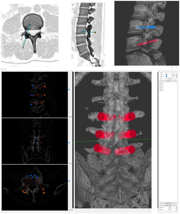
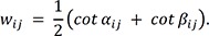
Our system provides a variety of views, such as MPR sectional and trajectory views and a 3D view. The MPR sectional view presents reconstructed images of three mutually perpendicular axes (X, Y, and Z) of the section. The trajectory MPR view presents reconstructed images of the cross-section perpendicular to the fixation direction of the screw and two cross-sections perpendicular to the first. Thus, the anatomical structure in the area of the screw placement can be clearly visualized (Fig. 1). The simulator receives the digital imaging and communications in medicine format image files obtained through CT, which are used to construct an image volume dataset. It resamples the volume to reconstruct MPR and trajectory MPR images. The 3D view shows the three-dimensional model of the spine generated from the 3D reconstruction process and screw models as a cylindrical shape.5 The screws are inserted in the model with an “insert” button. Generally, the spinal model is displayed as a translucent model, but it can be changed to opaque as needed.
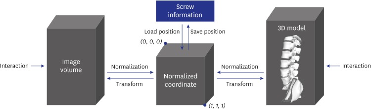
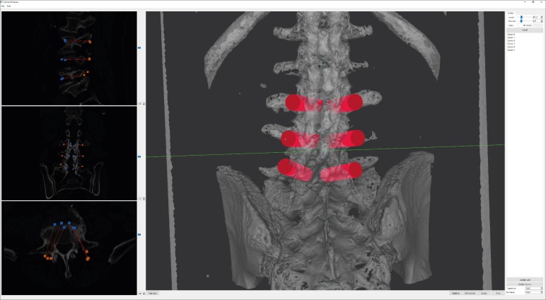
Since all these views are mutually connected, a single user's action on a view is reflected on other views. The input volume data and reconstructed 3D spinal models are defined in the different coordinate systems. Thus, the simulator stores the screw positions in this coordinate system normalized to a value between 0 and 1 to preserve coordinate consistency between the input volume data and the spinal geometric model. The normalized screw position inserted during the planning is recalculated when displayed on each view (Fig. 2).
Users can select and modify the virtual screws on the 3D model view. To do so, one point on the model must be selected. For this, casting a ray in the viewing direction of the mouse click point as the starting point finds the intersection of the triangle. Several triangles appear in this process. Among them, triangles in which the dot product of a normal vector and the ray direction is zero are excluded because they are invisible. The closest triangle is then selected by calculating the distance between the intersection point on the triangle and the starting point of the ray.
Surgical planning on 3D spinal model
With our simulator, the user can make a number of attempts to determine the screw-fixation position before actual spinal surgery without risk to the patient. This also enables predicting the difficulty of the surgery. The real-time interactions between the simulator and users allow multiple surgeons with varying levels of experience to share in visualizing the surgical planning simultaneously. Users can freely change the position and angle of the screws and produce MPR section, trajectory MPR section, and 3D model views; users are completely immersed in surgical planning.
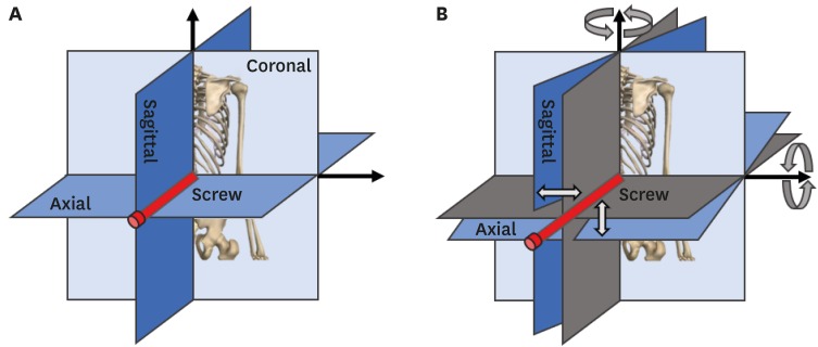
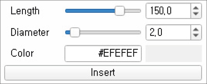
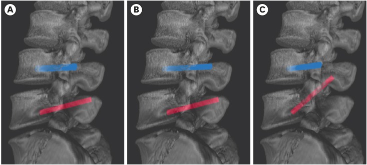
The fixation positions of the pedicle screws are determined on the MPR section view, and those are displayed to the MPR, the trajectory MPR, and the 3D views in the simulator. Users can select the screw fixation function and click the mouse on one of the MPR sections to examine the starting and ending point of a screw having a predefined length, diameter, and color, and these parameters are then recorded in the simulator (Fig. 3). The screws are recorded in order in the screw list in the simulator. When users select screws from the list, the corresponding screws are highlighted in a specified color in the MPR view and 3D model view. The length and diameter of the screws can be selected by using the existing inserted screw and modifying the values in a dialogue box (Fig. 4). The degree of angle of the screws can be changed on the 3D model view by dragging one or both of their end points. When changing the angle as above, the simulator updates the starting point of the screw using the direction from the ending point to the starting point and the screw length to keep the length constant (Fig. 5). The length and diameter of the screw can be changed by adjusting the dialog value of the screw selected.6
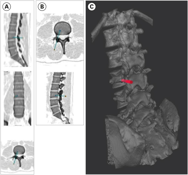 | Fig. 3MPR, trajectory of MPR section views, and 3D-view screenshots on the simulator. (A) MPR section view with a screw inserted, (B) trajectory MPR section view, and (C) 3D model view. Colors of the captured MPR and trajectory MPR view images were reversed to improve visibility.MPR = multiplanar reconstruction, 3D = three-dimensional.
|
Reconstruction and mesh smoothing of the 3D level-of-detail (LOD) model
The input data are the tomography images scanned by CT devices before spinal surgery. In our system, the marching cubes algorithm was used to reconstruct the 3D mesh.12 The roughness of the mesh surface, partial volume effects, and noise that occur during CT scanning make it difficult to construct a complete manifold model using the marching cubes algorithm.131415 In addition, overload on rendering pipelines may occur due to multiple vertices, requiring additional simplification or smoothing. We apply Laplacian smoothing161718 to smooth the rough surface of the mesh reconstructed by the marching cubes algorithm, and apply a mesh simplification algorithm based on quadric error metrics to generate an LOD model after applying Laplacian smoothing, and finally, we apply Taubin smoothing to smooth the 3D model to be displayed in our simulator (Fig. 6).1920
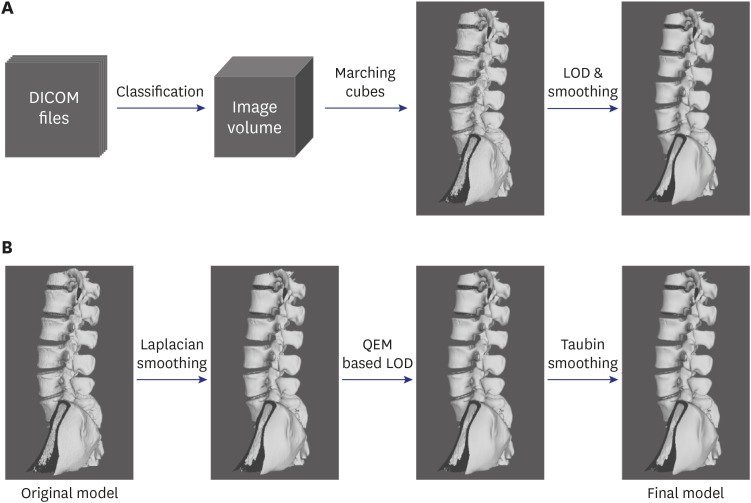 | Fig. 63D model reconstruction and additional process in this study. (A) Overall process of 3D model reconstruction using DICOM format computed tomography images, (B) additional smoothing and LOD application process for the original model created using the marching cube algorithm.DICOM = digital imaging and communications in medicine, LOD = level-of-detail, QEM = quadric error metric, 3D = three-dimensional.
|
Using the marching cubes algorithm, an image volume was constructed by stacking multiple images, and eight cubically adjacent neighborhoods of each voxel were then examined to compare with the value of the object boundary desired. A 3D mesh was then reconstructed by referring to the table in which the mesh pattern corresponding to the result of the comparison was defined.2122 This has the advantage of parallel processing by referring to the predefined mesh pattern table.23
The quadric error metric mesh simplification algorithm was used to calculate the sum Qp of quadric Q1 and Q2 for any vertex pair (v1, v2) in the mesh and to calculate the minimum error EQp = v̄TQpv̄ at the time of decimating the vertex pair to a new vertex, v̄. Decimating the vertex pair with the minimum error was performed repeatedly.2425 This method has a lower error rate and execution time but higher memory usage than other mesh simplification algorithms.26 A low error rate and execution time are more important than low memory usage in preoperative planning, because our system is executed on a workstation or PC.
Laplacian smoothing was applied to smooth out the mesh generated by marching cubes.1618 Laplacian smoothing can cause mesh shrinkage. The mesh shrinkage rate of Laplacian smoothing increases as mesh density decreases or as the number of iterations increases.2728 Mesh shrinkage resulting from smoothing algorithms precludes the ability to preserve the whole shape and the spinal canal shape of the spinal mesh, meaning that surgeons cannot plan surgery precisely. For these reasons, we applied Laplacian smoothing before generating the LOD models of the spinal mesh and only a small number of iterations.
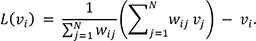
Laplacian smoothing was applied to move a vertex, vi, in the mesh to a new vertex, vnew. vnew is the weighted average for N-adjusted vertices, vj. The equation to obtain vnew can be expressed as:
where L(Vi) is a vector average between the vertex vi and the adjusted vertices vj. L(Vi) can be expressed as follows:
When Wij was the weight of each of the adjusted vertices, the cotangent weight was used, as follows:
Although Laplacian smoothing was applied before generating the LOD models, the surface of the mesh generated by the LOD algorithms may not be smooth. Therefore, additional smoothing was required to smooth the surface after generating the LOD models. As the LOD model has a low vertex density, repeated applications of Laplacian smoothing may result in greater mesh shrinkage than when the vertex density is low. Therefore, Taubin smoothing was applied instead of Laplacian smoothing.2930 Although it has less smoothing effect than Laplacian smoothing, it can prevent mesh shrinkage via the application of a mesh shrinkage step and an expansion step in each iteration.2931 Each step of Taubin smoothing is similar to Laplacian smoothing. These two steps can be expressed as:
where the parameters λ and μ are the scale variables of L(vi), and the weight of L(vi) in Taubin smoothing can be chosen in a variety of ways. We applied the same weight as in Laplacian smoothing.32 Thus, in the first step of Taubin smoothing, the mesh shrinks as in Laplacian smoothing. In the second step, the mesh expands by reversing the sign of the scale variable. These two smoothing steps produced the smoothing effect and prevented mesh shrinkage.
Application
Patient population and radiographic evaluation
We retrospectively reviewed postoperative CT data of 16 patients who underwent pedicle screw fixation in the lumbar spine, after preplanning using this preoperative system. The procedures were performed by a single orthopedic surgeon at our tertiary teaching hospital, in September and October 2019.
Planning process
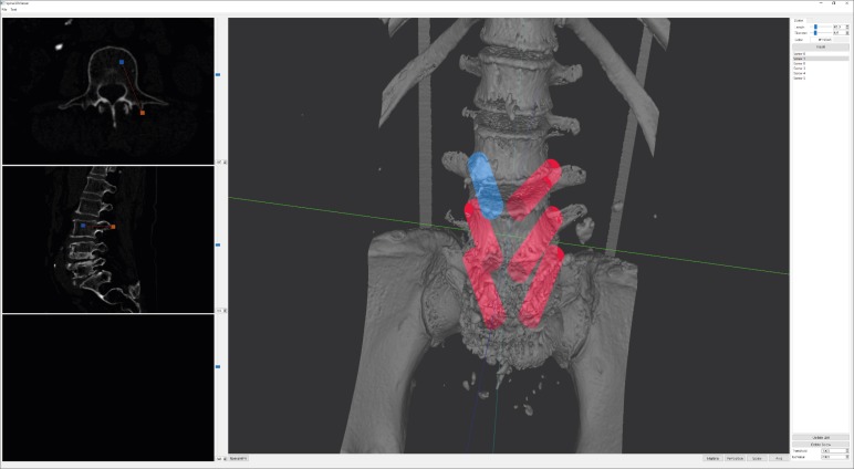
We used the developed simulator in preoperative planning to determine the most appropriate position of pedicle screws in spinal surgery. The appropriate position of pedicle screws is at an angle parallel to the vertebral endplates, with the length and diameter of the pedicle screw passing through the pedicle without damaging the anterior cortex of the vertebral body (Fig. 7). Preoperative planning was carried out for all pedicles that were to have pedicle screws inserted. The screw-fixation planning was mainly carried out on the MPR section, and the trajectory MPR view was used to confirm that each screw was in the proper position (Fig. 8). Finally, we checked the entry point, convergence angle, diameter, and length of the pedicle screws in the 3D image.
Radiographic evaluation
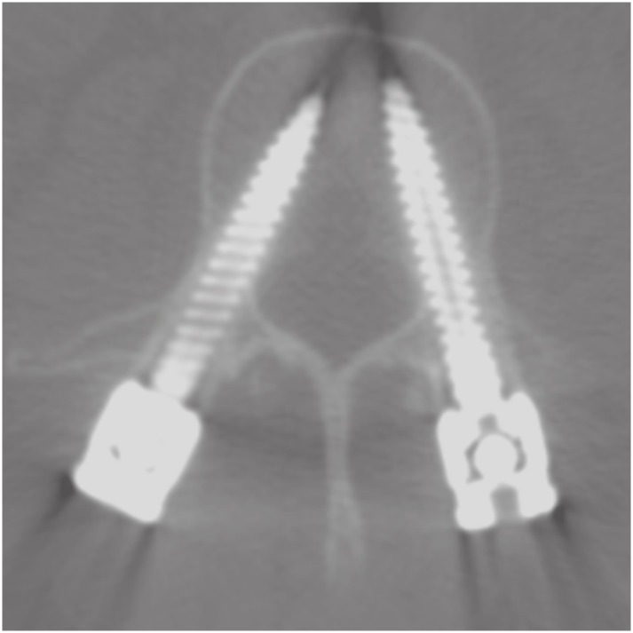
The accuracy of pedicle-screw placement was evaluated using postoperative CT by two independent orthopedic surgeons (OK, a fourth-year orthopedic resident, and HH, a third-year orthopedic resident). The accuracy of pedicle-screw position was measured using Gertzbein and Robbins classification: Grade A, the screw is completely within the pedicle; Grade B, the screw breaches the pedicle's cortex by less than 2 mm; Grade C, pedicle cortical breach is between 2 and 4 mm; Grade D, pedicle cortical breach is between 4 and 6 mm; and Grade E, pedicle cortical breach is 6 mm or more.33
Statistical analysis
Interobserver agreement was analyzed using kappa values. The level of agreement was interpreted as slight when kappa value was 0 to 0.2, fair when kappa value was 0.2 to 0.4, moderate when kappa was 0.4 to 0.6, substantial when kappa value was 0.6 to 0.8, and almost perfect when kappa value was greater than 0.8. Stata/MP 15.0 (Stata Statistical Software, Release 15; StataCorp LLC, College Station, TX, USA) was used for the statistical analysis.
Ethics statement
This retrospective case series study of pedicle screw placement after the use of the preoperative pedicle screw planning system was approved by the Institutional Review Boards of Seoul National University Bundang Hospital, who waived informed consent (B-1911-576-101).
Go to :
RESULTS
The 16 patients included in our study consisted of 6 (38%) men and 10 (62%) women, with a mean age of 67.9 years (range, 54–83 years) at the time of first visit. A total of 82 pedicle screws were reviewed in our study. Detailed demographic data are shown in Table 1.
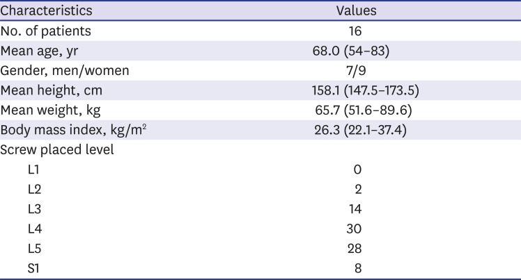
Table 1
Demographic data of the patients included in this study
![]()
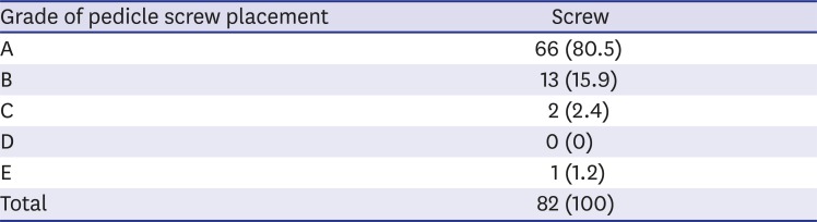
The rate of grade A accuracy of pedicle-screw fixation was 80.5%, and the rate of grade A and grade B accuracy combined was 96.4%. The failure rate of pedicle-screw fixation was 3.6% (Table 2). There were no cases of neurovascular injury or life-threatening major complications. There was almost perfect agreement between observers for evaluating pedicle-screw accuracy by CT (kappa value = 0.896).
An LOD model was generated and compared to each model according to smoothing algorithms applied (Fig. 11). The LOD model reduced vertices of the mesh generated by marching cubes to about 10%. The model has 265,525 vertices. Laplacian smoothing was applied in 8 iterations and Taubin smoothing was applied in 30 iterations. One of the Taubin smoothing parameters, λ, is 0.50, and the other, μ, is −0.53.
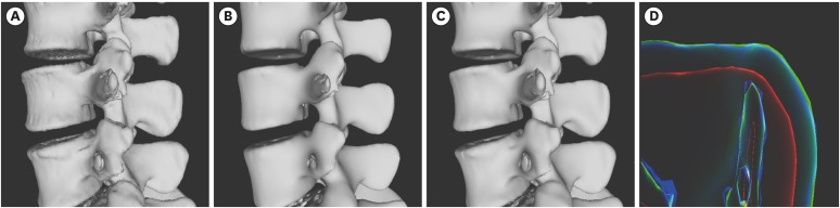 | Fig. 11Visual comparison of LOD model and models of application of Laplacian and Taubin smoothing. (A) The LOD model, (B) the model that applied Laplacian smoothing in 8 iterations, (C) the model that applied Taubin smoothing in 30 iterations, (D) rendering image using x-ray shader for visual comparison of these models. The blue outline is the outline of (A), the red is (B) and the green is (C).LOD = level-of-detail.
|
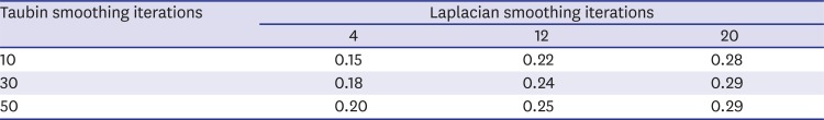
The model was compared visually and measured for errors according to the smoothing algorithm type and iterations before and after the LOD model was generated (Fig. 12 and Table 3). The average Hausdorff distance was applied to assess the error.3435 Five hundred thousand sample points were taken from the LOD model without any smoothing, and this was used to measure the error with the model after smoothing.
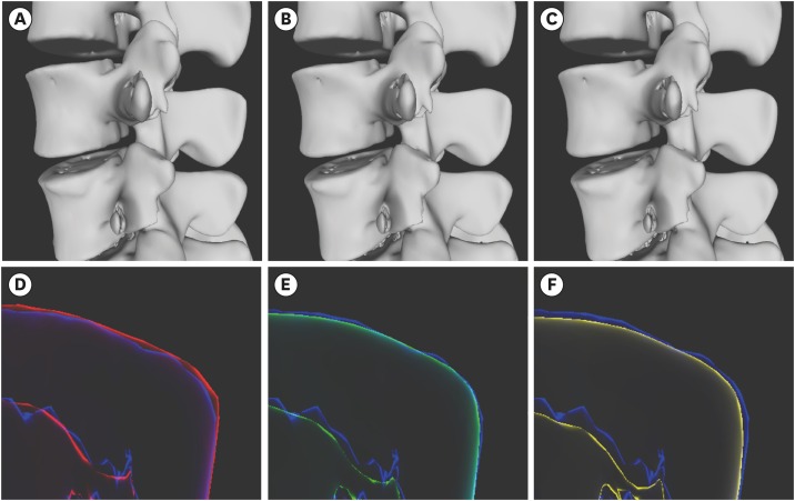 | Fig. 12Visual comparison of results models according to the number of Laplacian and Taubin smoothing applications. (A), (B), and (C) are the models that received 4, 12, and 20 iterations of Laplacian smoothing and 50, 30, and 10 iterations of Taubin smoothing. (D), (E), and (F) are the rendering images using X-ray shader for visually comparing the model size changes according to the iterations of each smoothing algorithm applied. The blue outline is the level-of-detail model, as in Fig. 11A.
|
Go to :
DISCUSSION
Pedicle-screw fixation is a common procedure in spinal surgery. It is technically difficult, requiring a prolonged learning period. Pedicle screw-related complications occur, especially early in the learning period. Our preoperative planning system is useful for accurate pedicle-screw planning of entry point, convergence angle, length and diameter, and 3D visualization of planned pedicle screws.
Eftekhar et al.9 developed a program in Windows to simulate pedicle-screw fixation on the vertebral body, but the program was impractical because it could not analyze patients' specific anatomical variations. Klein et al.11 developed software in the form of a plug-in for AmiraDev software (Visage Imaging, Carlsbad, CA, USA). Similar to our software, it has the advantage of preoperative planning for each patient by CT, but AmiraDev is inconvenient for use in the clinical setting because it is commercial software with a prohibitive cost. In a recent study, the authors introduced a pedicle screw simulator for use before actual operations,6 but it can be used only experimentally, as it has not been used in real-world conditions.
There is commercial spinal planning software from Brainlab (Brainlab, Munich, Bayern, Germany), but it is designed for planning during surgery and part of a system configured for use with other surgical equipment. While it provides MPR and trajectory views, it lacks a 3D view. Surgimap is free software for surgical planning (Nemaris, NY, USA), but it does not provide a 3D view and allows surgical planning for a single image only. The length and diameter of pedicle screws can be determined and corrected on the image using only a mouse, but it cannot correct directly by changing numerical values. The 3D Slicer is open-source image analysis and visualization software freely available. The spinal surgery planning feature is provided in a downloadable extension of the program called the Pedicle Screw Simulator. This extension works well for our purposes, but the pedicle screw in the extension cannot be inserted and corrected using mainly the view, but only in the dialog screen, making it more complicated, and the length and diameter of the insertable screw are limited to certain kinds. In the latest version currently available for download, the available pedicle screws include only 47.5, 55.0, 62.5, and 70.0 mm in length, and 3.0, 3.5, 4.5, and 5.0 mm in diameter.
The software described in the present study allows users to determine the entry point, direction, convergence angle, diameter, and length of pedicle screws before spinal surgery. As in a general PACS, the user first determines the positions of the screws on the MPR view and then affirms these on the 3D model view and trajectory MPR view to ensure that they are planned in the correct positions.
During an actual operation, preplanning makes it easy to see where to insert the screws and at what position and convergence angle (Fig. 8). The preoperative planning images can be compared with postoperative CT images to confirm that the screws are similar to the preoperative plan (Fig. 9). Our surgical planning system aids preoperative planning by surgeons who are unfamiliar with pedicle-screw fixation and provides them a risk-free environment. It can serve as an aid to training by allowing users to indirectly experience and practice screw fixation in a variety of patients. According to a previously published paper, an accuracy of grade B and higher during pedicle-screw fixation was 92.9%.1 The accuracy shown in this study is higher than in the previous study, so it can be concluded that preoperative planning is effective in increasing accuracy.
In our system, postprocessing algorithms, such as generating the LOD model and mesh smoothing, are applied to improve the program's execution time and the quality of the model. In particular, we compared the difference of mesh size and the Hausdorff error of the smoothing protocols of Laplacian and Taubin. The outline of the model smoothed by Laplacian smoothing is inside than the LOD model, while the outline of the model smoothed by Taubin smoothing is similar to the LOD model. It can be seen visually that applying Laplacian smoothing to the LOD model can cause unintentional volume shrinkage and shape deformation (Fig. 11). Thus, applying Taubin smoothing to the LOD model demonstrated less size shrinkage than Laplacian smoothing.
When Laplacian smoothing was applied before LOD generation and turbine smoothing after, the models were compared visually according to the number of smoothing applications, and no significant difference was found (Fig. 12). Numerical error was measured to compare the LOD model and smoothing models. If the number of Laplacian smoothing iterations before generating the LOD model is lower—even if the number of Taubin smoothing iterations is higher—the numerical error is small (Table 3). Therefore, it is important to determine accurately the number of iterations of smoothing algorithms that can minimize errors and preserve the mesh size.
In the future, the preoperative planning system will be combined with virtual reality via a virtual simulator of an actual operation to allow users to experience surgery before an actual operation. It could be developed as a planning simulator that can also simulate a real surgical environment. The potential training value of a preoperative planning system for junior surgeons and medical students will first need to be evaluated.
The preoperative planning system is expected to play an increasingly important role in creating a risk-free virtual surgical environment. In particular, it can allow junior surgeons and medical students to practice preoperative planning and perform a simulation. Although the simulator needs further development, we believe that it can play an important role in spinal surgery by increasing familiarity with anatomic deformities, improving surgical outcomes, and reducing complications.
Go to :
 XML Download