INTRODUCTION
DIAGNOSIS AND ETIOLOGY
TREATMENT OBJECTIVES
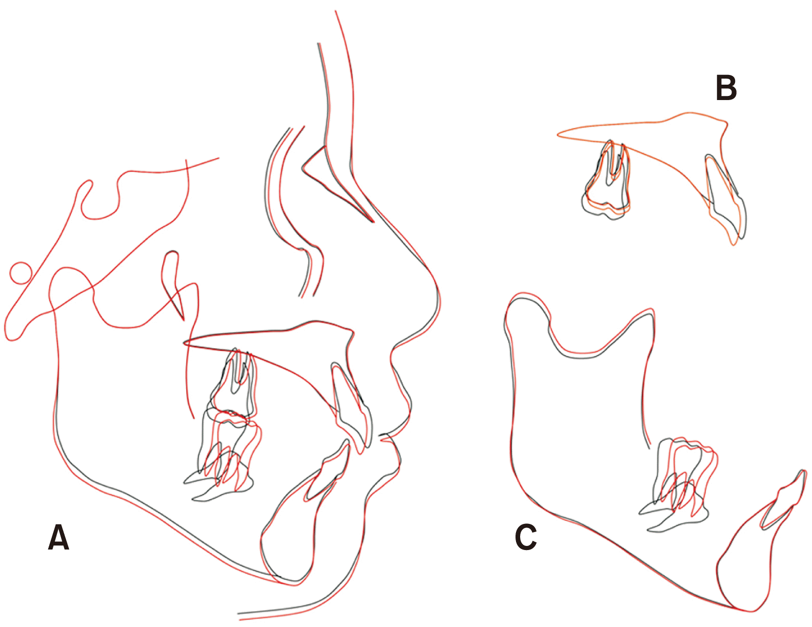
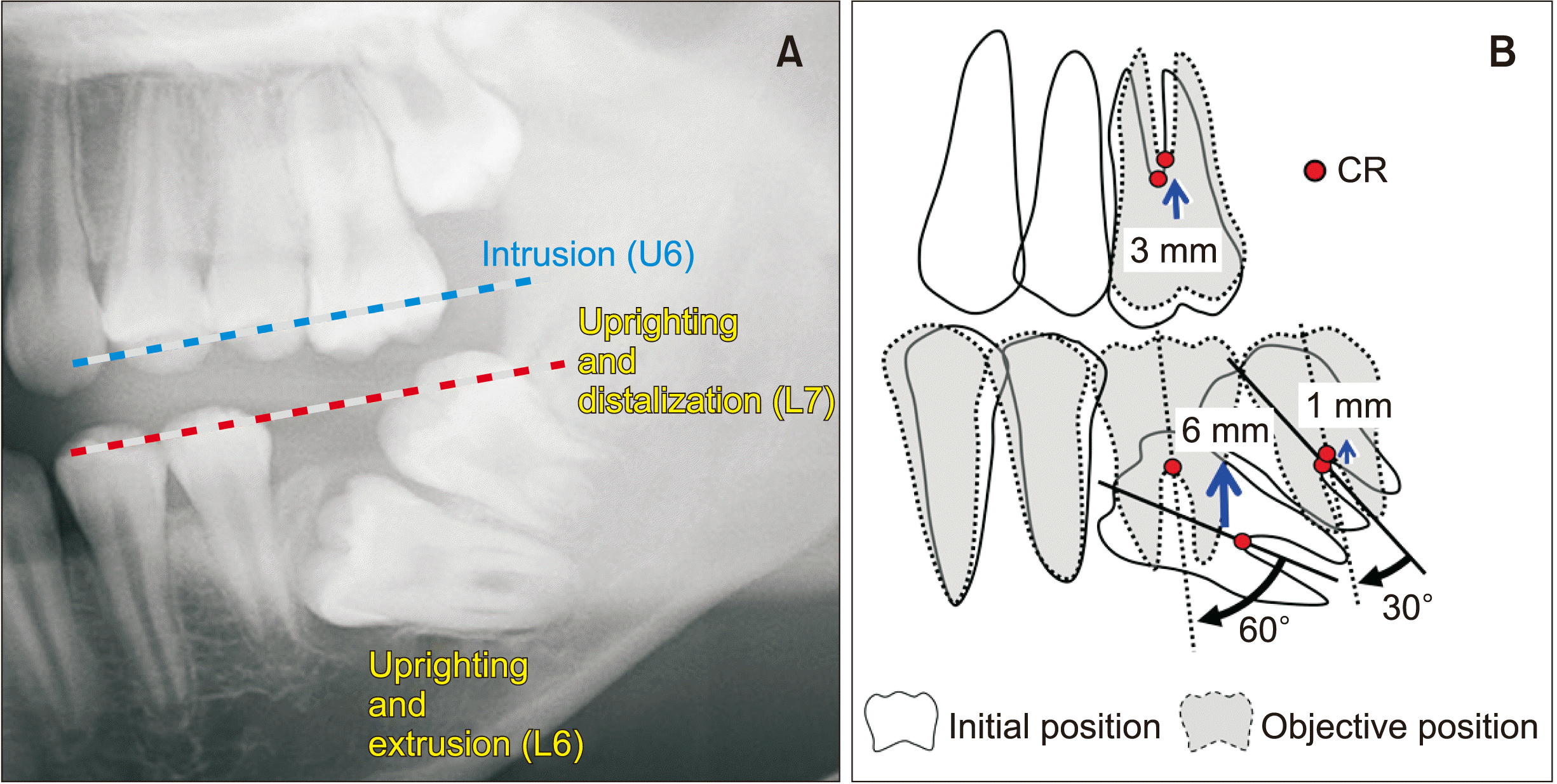 | Figure 4Treatment objectives. A, Treatment plan for repositioning of the molars. B, Schematic diagram of treatment objectives. The maxillary first molar is intruded by 3 mm. The mandibular first and second molars are uprighted by 60° and 30°, and extruded by 6 mm and 1 mm, respectively.
U6, Upper first molar; L6, lower first molar; L7, lower second molar; CR, center of resistance.
|
TREATMENT ALTERNATIVES
TREATMENT PROGRESS
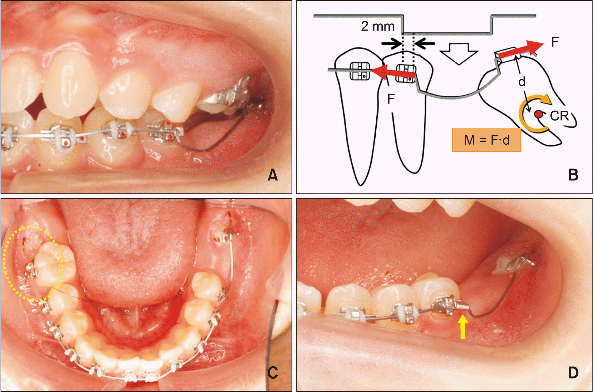 | Figure 5Progress and force system for uprighting the mandibular second molar. A, Left mandibular second molar uprighting using a 0.016 × 0.016-inch (in) square nickel-titanium (NiTi) archwire with two step bends whose distance was 2 mm wider than the inter-bracket distance between the left second premolar and the second molar. B, Force system acting on the second molar when the uprighting mechanics using a compression force is employed. Two step bends, whose distance is 2 mm wider than the inter-bracket distance between the second premolar and second molar, are incorporated into a 0.016 × 0.016-in square NiTi archwire. When the two step bends incorporated into the archwire are squeezed and engaged into the brackets, a mesial force to the second premolar and a distal force to the second molar are generated. Then, an uprighting moment (M), whose magnitude is the product of the magnitude of the distal force (F) and the perpendicular distance (d) from its line of force to the center of resistance (CR), is produced. C, The length of the excess wire distal to the buccal tube on the right first molar was used to shift the archwire to the left to reactivate the two step bends without removing the archwire (circle). D, A crimpable stop placed on the archwire just mesial to the anterior step bend (arrow). |
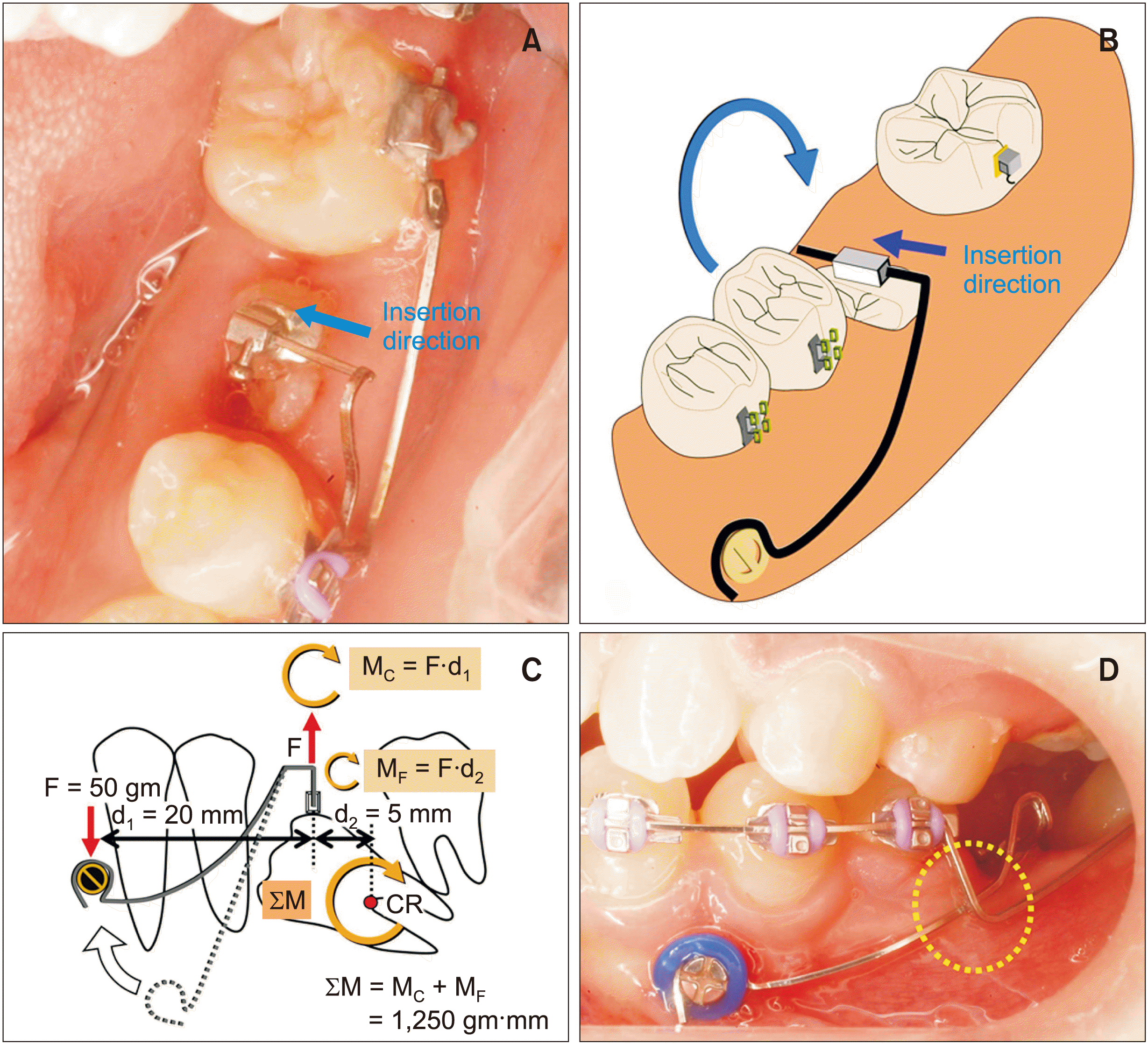 | Figure 6Treatment mechanics for uprighting of the left mandibular first molar. A, B, A small molar tube bonded buccolingually and an arrow indicates the insertion direction of the cantilever. C, Force system acting on the first molar and miniscrew when the cantilever mechanics is employed. A dotted line indicates the cantilever in its passive state, and a solid line in its active state. When the cantilever is activated, a moment of couple (MC) to tip the molar distally, an extrusive force on the molar tube, and an intrusive force on the miniscrew are generated. The uprighting moment acting on the molar is the sum of MC and the moment of force (MF). D, The cantilever passes under the main archwire to avoid slipping buccally and the mesial end of the cantilever hooked over the miniscrew (circle). |
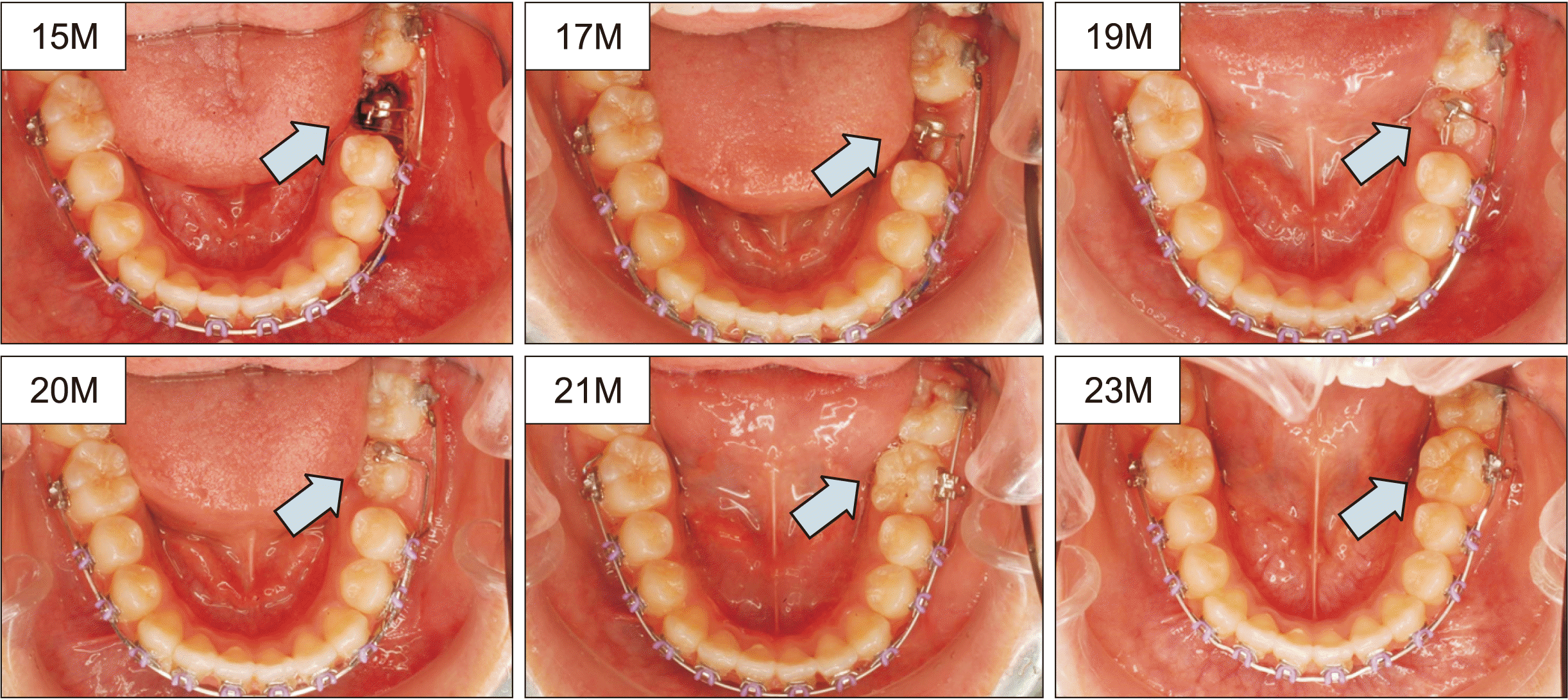 | Figure 7The treatment sequence for uprighting of the left mandibular first molar (the blue arrow indicated) (15M; 15 months after orthodontic treatment started). Progress is shown at treatment times in months. The archwire was 0.017 × 0.022-inch (in) Elgiloy and a 0.016 × 0.022-in stainless steel cantilever was used for uprighting the left mandibular first molar. At 21 months, a molar tube was bonded on the buccal surface of the first molar and the 0.018-in nickel-titanium archwire was engaged for its alignment. |


 PDF
PDF Citation
 Print
Print




 XML Download