This article has been
cited by other articles in ScienceCentral.
Abstract
Root resorption can be caused by several factors, including contact with the cortical bone. Here we report a case involving a 21-year-old female with Angle Class II, division 1 malocclusion who exhibited significant root resorption in the maxillary right central incisor after orthodontic treatment. The patient presented with significant left-sided deviation of the maxillary incisors due to lingual dislocation of the left lateral incisor and a Class II molar relationship. Cephalometric analysis demonstrated a Class I skeletal relationship (A point-nasion-B point, 2.5°) and proclined maxillary anterior teeth (upper incisor to sella-nasion plane angle, 113.4°). The primary treatment objectives were the achievement of stable occlusion with midline agreement between the maxillary and mandibular dentitions and appropriate maxillary anterior tooth axes and molar relationship. A panoramic radiograph obtained after active treatment showed significant root resorption in the maxillary right central incisor; therefore, we performed cone-beam computed tomography, which confirmed root resorption along the cortical bone around the incisive canal. The findings from this case, where different degrees of root resorption were observed despite comparable degrees of orthodontic movement in the bilateral maxillary central incisors, suggest that the incisive canal could be an inducing factor for root resorption. However, further investigation is necessary to confirm this assumption.
Go to :

Keywords: Root resorption, Computed tomography, Digital models, Incisive canal
INTRODUCTION
Cases of Angle Class II, division 1 malocclusion often show root resorption in the maxillary anterior teeth after orthodontic treatment.
1 In recent years, the innovation of implant anchorage systems has enabled a large amount of maxillary anterior tooth retraction,
2 which in turn has increased the risk of root resorption in the maxillary anterior teeth. There are various contributing factors for root resorption, including root proximity to the cortical bone.
3,4 In the maxillary anterior region, cortical bone is present not only on the labial/palatal side but also around the incisive canal, and root resorption due to root contact with the bone around the incisive canal has been suggested.
5,6 However, because root resorption is influenced by various factors such as the magnitude of force
7 and amount of tooth movement,
8 it is difficult to rule out other factors and conclude that root contact with the cortical bone around the incisive canal is the cause for resorption. Here we report an orthodontic case involving a 21-year-old female with Angle Class II, division 1 malocclusion who exhibited significant post-treatment root resorption in the maxillary right central incisor that was caused by contact of the root with the cortical bone around the incisive canal. This report evaluates the relevance of root resorption and root contact with the cortical bone around the incisive canal by performing three-dimensional (3D) cone-beam computed tomography (CBCT) evaluations for the measurement of movement before and after active treatment and preparing 3D models of the maxillary central incisors and the incisive canal with the surrounding bone.
Go to :

DIAGNOSIS AND ETIOLOGY
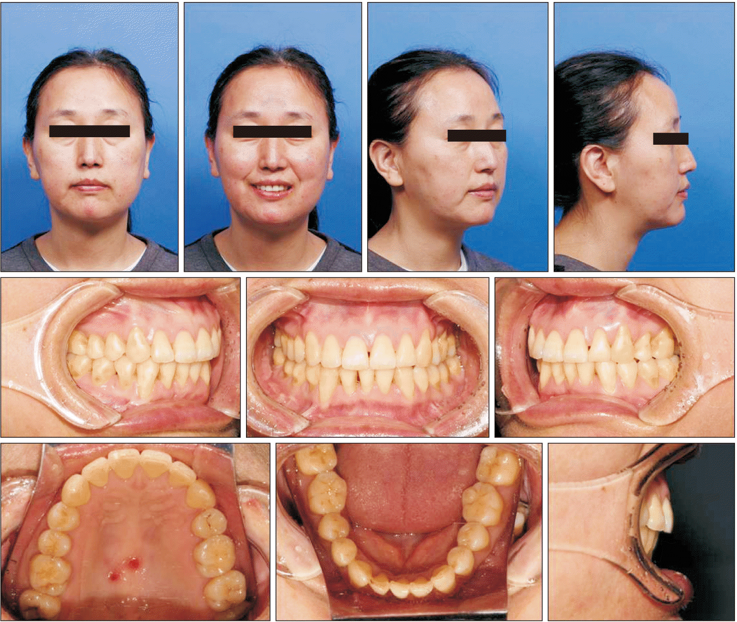
A 21-year-old female presented with a chief complaint of crowding in the maxillary anterior region (
Figure 1). She had no history of systemic diseases or allergies. Her dental history was also unremarkable, with no history of trauma to the anterior teeth. Facial photographs showed deviation of the maxillary and mandibular midlines relative to the facial midline; the maxillary midline was deviated to the left by 5.0 mm and the mandibular midline was deviated to the right by 1.5 mm. The upper and lower lips showed protrusion of 2.4 and 4.0 mm, respectively, from the esthetic line (E-line) (
Figure 1).
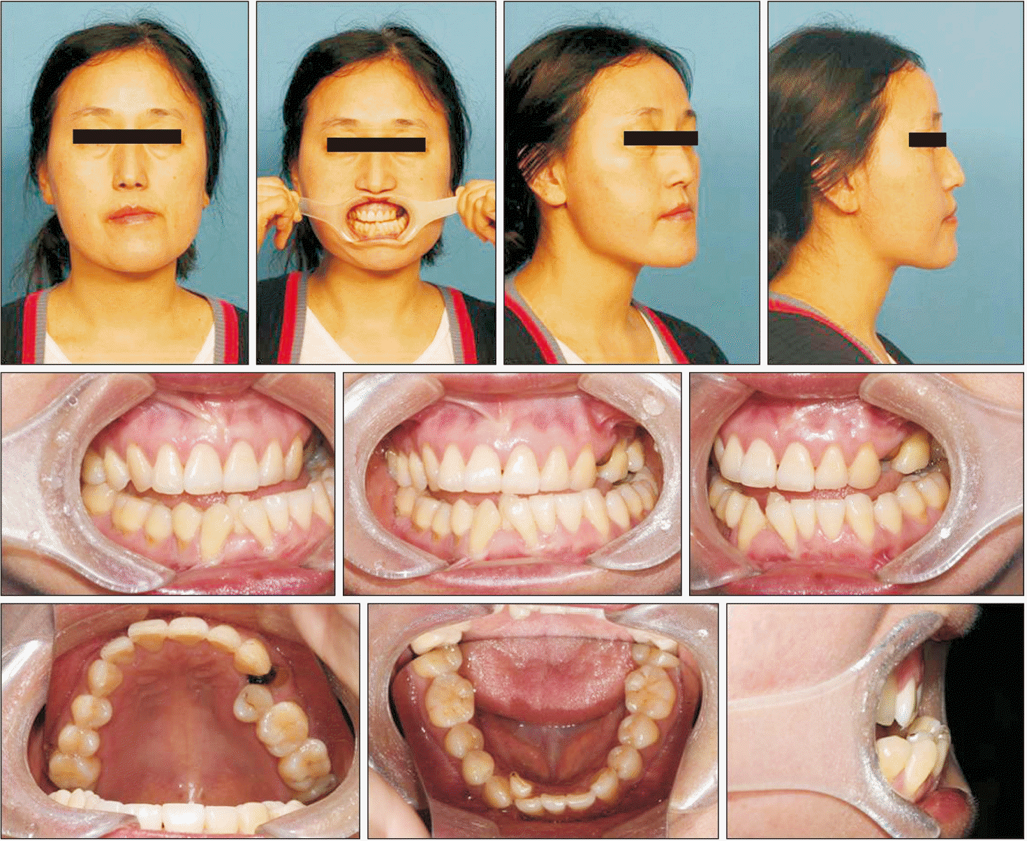 | Figure 1Pretreatment facial and intraoral photographs. 
|
Model analysis showed Angle Class I molar and Class II canine relationships with an overjet of 5.3 mm and overbite of 6.1 mm; lingoversion of the maxillary left lateral incisor, which resulted in crossbite; and arch length discrepancies of −9.4 and −5.5 mm in the maxilla and mandible, respectively (
Figures 1 and
2). A panoramic radiograph showed impaction of the bilateral maxillary third molars (
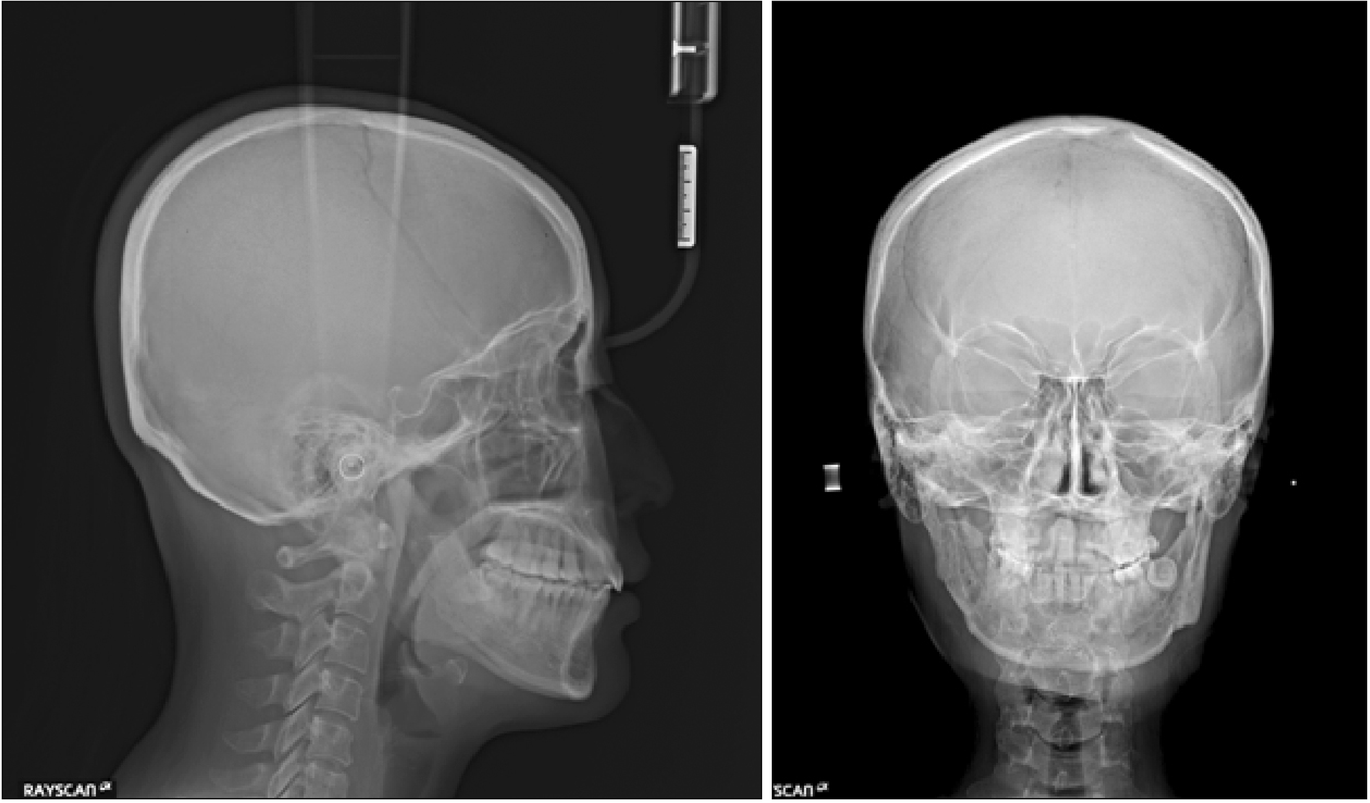
Figure 3). Cephalometric analysis demonstrated a Class I skeletal relationship (A point-nasion-B point [ANB] angle, 2.5°) and labial inclination of the maxillary incisors (upper incisor to sella-nasion plane angle [U1 to SN], 113.4°;
Table 1). The midlines of the maxillary and mandibular incisors observed on a posteroanterior (PA) cephalogram corresponded to those observed during extraoral examination (
Figure 3). In addition, CBCT (Finecube; Yoshida, Tokyo, Japan) of the maxillary anterior alveolar region showed a large incisive canal in close proximity to the roots of the maxillary central incisors (
Figure 4). We also used the CBCT image to assess the feasibility of using mini-screws and their implantation sites.
 | Figure 2Pretreatment dental casts. 
|
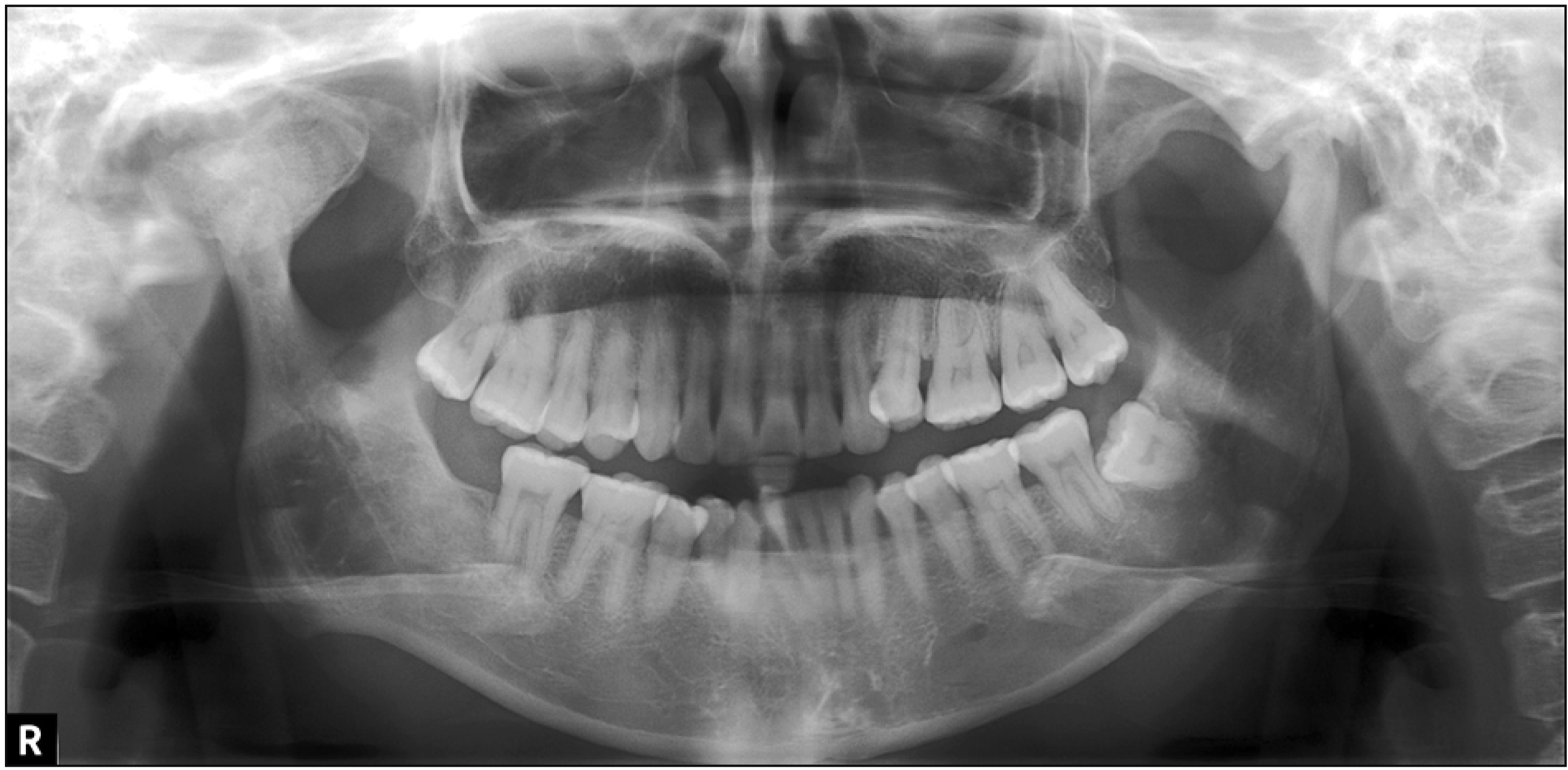 | Figure 3Pretreatment radiographs. A, Lateral cephalogram. B, Posteroanterior cephalogram. C, Panoramic radiograph. 
|
 | Figure 4Pretreatment cone-beam computed tomography images. A, Transverse image at the apex level of the maxillary incisor roots. B, Parasagittal image of the maxillary right central incisor. C, Parasagittal image of the maxillary left central incisor. 
|
Table 1
Pre- and post-treatment cephalometric variables with reference values
|
Measurement (°) |
Pretreatment |
Post-treatment |
Norm9,*
|
|
SNA |
79.5 |
79.0 |
82.3 ± 3.5 |
|
SNB |
77.0 |
77.0 |
78.9 ± 3.5 |
|
ANB |
2.5 |
2.0 |
3.4 ± 1.8 |
|
FMA |
33.3 |
33.3 |
28.8 ± 5.2 |
|
U1 to SN |
113.4 |
101.0 |
104.5 ± 5.6 |
|
IMPA |
85.6 |
83.5 |
96.3 ± 5.8 |
|
FMIA |
61.1 |
63.2 |
54.6 ± 6.5 |

Go to :

TREATMENT OBJECTIVES
The primary treatment objectives were as follows: to coincide the maxillary and mandibular incisor midlines, eliminate the crossbite by reversing the lingoversion of the maxillary left lateral incisor, normalize the labial inclination of the maxillary anterior teeth, and establish a satisfactory facial profile and occlusion by normalizing the overjet and overbite and achieving Class I canine and appropriate molar relationships.
Go to :

TREATMENT ALTERNATIVES
We explored three treatment alternatives to meet the treatment objectives.
The first one involved extraction of the bilateral maxillary first premolars and mandibular second premolars, followed by application of maximum anchorage in the maxilla and moderate anchorage in the mandible for mesialization of the mandibular molars. The second one involved extraction of the bilateral maxillary and mandibular first premolars, followed by application of maximum anchorage in the maxilla. The third one involved extraction of the bilateral maxillary lateral incisors and mandibular first premolars, followed by application of maximum anchorage in the maxilla and moderate anchorage in the mandible for mesialization of the mandibular molars.
All three options involved extraction of the bilateral maxillary third molars, and the first and second options involved the use of mini-screws in the maxilla. Although both options would involve lingual inclination and movement of the maxillary and mandibular incisors, the extent of change would be greater with the second option. The third option had an advantage of a shorter treatment duration achieved by extraction of the maxillary lateral incisor exhibiting lingoversion; however, there were serious concerns regarding the guidance for mandibular lateral movement and esthetics, which could be compromised by differences in the crown morphologies. After extensive discussion with the patient, we selected the first option after considering the arch length discrepancies, incisal axes, and anatomical structure of the incisive canal.
Go to :

TREATMENT PROGRESS
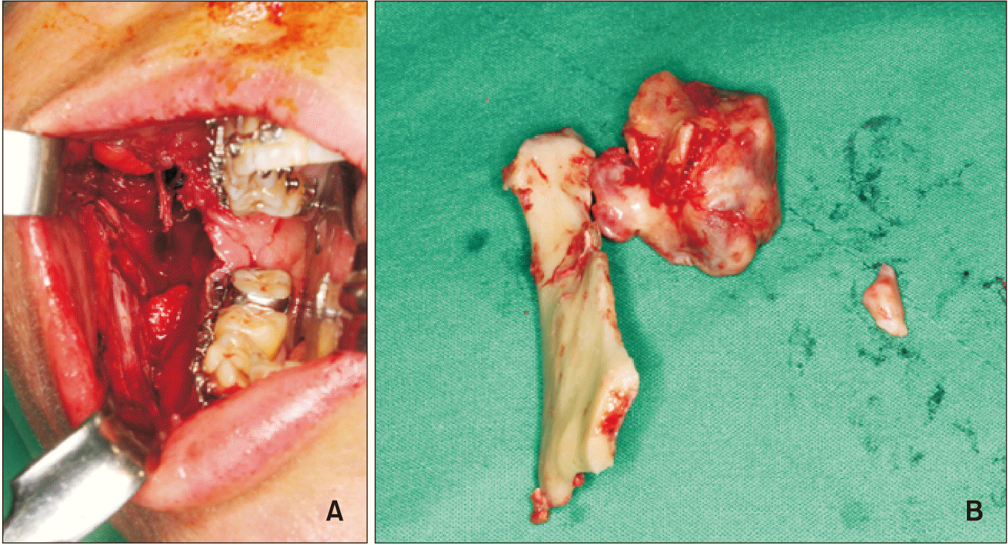
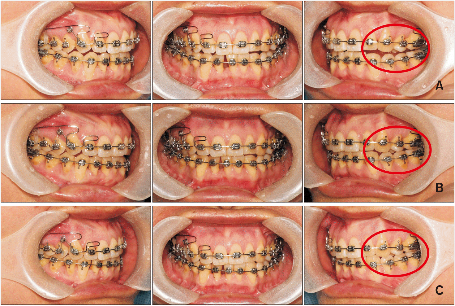
The bilateral maxillary first premolars and third molars and the bilateral mandibular second premolars were extracted before orthodontic treatment initiation. Preadjusted brackets with 0.018-inch slots (Dentsply Sirona Japan, Tokyo, Japan) were bonded to each tooth, and 0.016 × 0.022-inch improved superelastic nickel-titanium (Ni-Ti) archwires improved superelastic nickel-titanium archwires (ISW) (L&H; Tomy International, Tokyo, Japan) were used as the working archwires throughout the active treatment period. The long hooks were attached on the brackets of the mandibular first molars to prevent mesial inclination. After 1 month, a mini-screw (Dual Top; Jeil Medical Co., Seoul, Korea) was inserted in the buccal bone between the maxillary second premolars and first molars on both sides, and retraction of the maxillary canines was initiated with ISW incorporating gable bends between the canines and second premolars (
Figure 5A). A Ni-Ti open-coil spring (50 g) was simultaneously placed between the maxillary left central incisor and canine for movement of the maxillary midline to the right. At 3 months, brackets were bonded to the mandibular incisors for leveling with a 0.016 × 0.022-inch ISW. Subsequently, at 9 months, a bracket was bonded to the maxillary left lateral incisor for correction of the lingoversion and crossbite with a 0.016 × 0.022-inch ISW (
Figure 5B). At 13 months, maxillary anterior retraction was initiated with a 0.016 × 0.022-inch ISW incorporating a compensating curve in the premolar and molar regions (
Figure 5C). Subsequently, detailing with Class II elastics was initiated at 15 months. After 30 months of active treatment, the maxillary and mandibular incisor midlines coincided and the brackets and mini-screws were removed. Immediately after removal, a circumferential retainer for the maxilla and a Hawley retainer for the mandible were delivered.
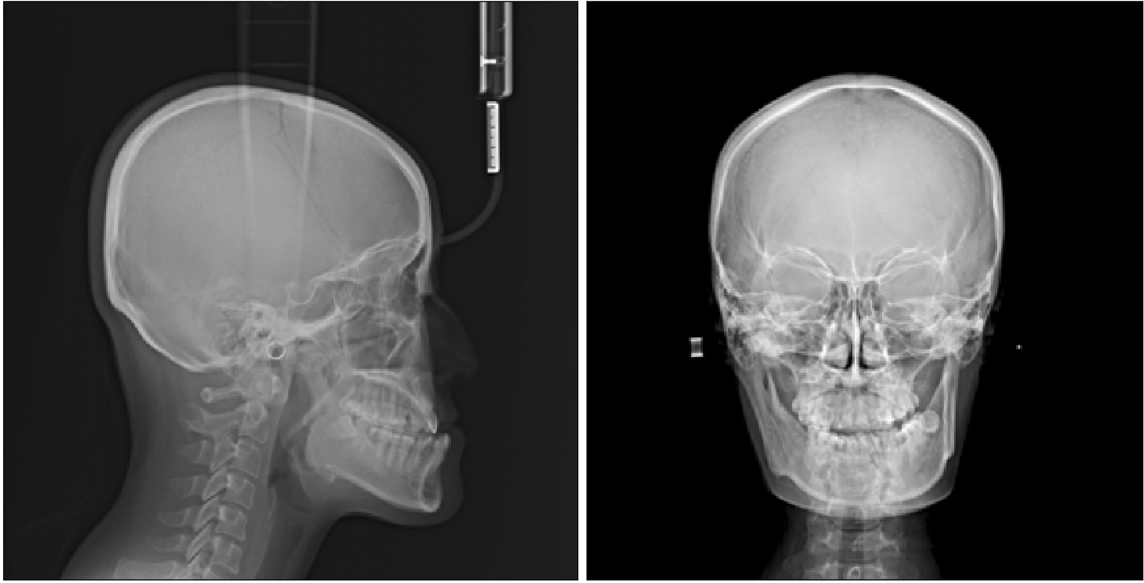 | Figure 5Treatment progress. A, After 1 month of active treatment. B, After 9 months of active treatment. C, After 13 months of active treatment. 
|
Go to :

RESULTS
Although the upper lip protruded by 2.4 mm and the lower lip protruded by 4.0 mm from the E-line before treatment, the amount of protrusion was decreased to 0.2 and 0.9 mm, respectively. The maxillary and mandibular incisor midlines coincided (
Figures 6 and
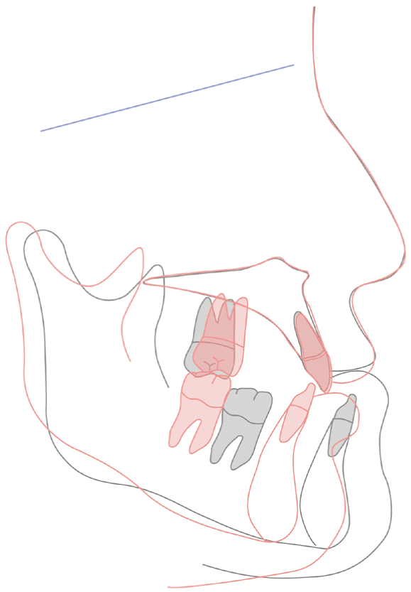
7). The U1 to SN angle changed from 113.4° to 101.0°, the maxillary incisor axis was within the mean normal range, and the Frankfort mandibular incisor angle changed from 61.1° to 63.2°. Among skeletal parameters, the sella-nasion-A point, sella-nasion-B point, and ANB angles were within the normal ranges, with no clockwise rotation of the mandible
9 (
Figures 8,
9, and
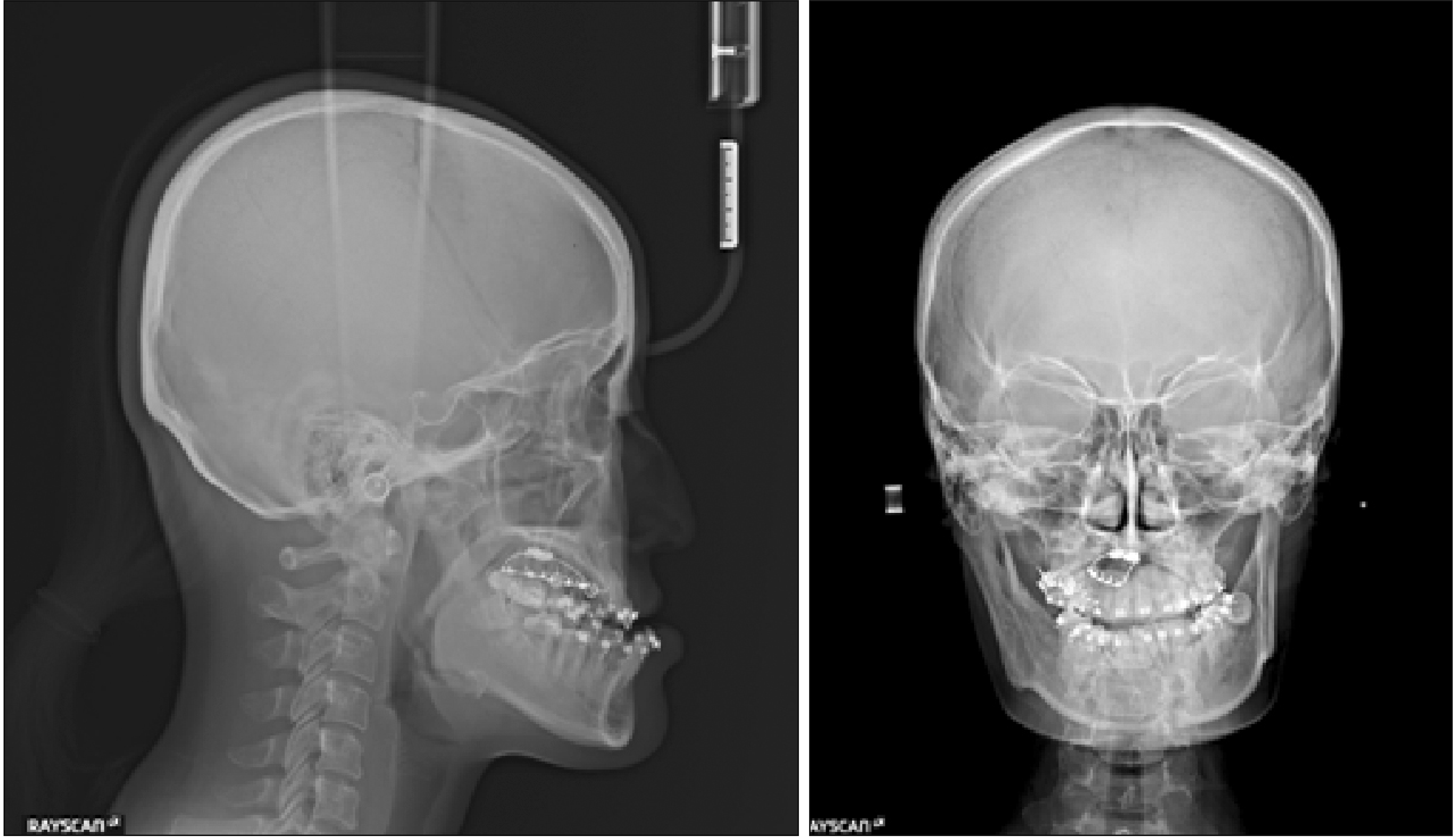
Table 1). However, because of space gain for the maxillary left lateral incisor and movement of the maxillary midline to the right, insufficient incisor root parallelism with tilting of the maxillary incisors to the right was observed on a post-treatment panoramic radiograph and PA cephalogram (
Figure 10): the angle between the facial and maxillary incisor midline was changed from 12.2 degree to −3.5 degree. Furthermore, the maxillary right central incisor, but not the left one, showed signs of significant root resorption. Therefore, we performed CBCT to confirm the condition of the incisor roots in three dimensions (
Figure 11).
 | Figure 6Post-treatment facial and intraoral photographs. 
|
 | Figure 7Post-treatment dental casts. 
|
 | Figure 8Post-treatment radiographs. A, Lateral cephalogram. B, Posteroanterior cephalogram. C, Panoramic radiograph. 
|
 | Figure 9Superimposed tracings of pre- (black line) and post-treatment (red line) lateral cephalograms. A, Superimposition on the sella-nasion plane at the sella. B, Superimposition on the palatal plane at anterior nasal spine. C, Superimposition on the mandibular plane at the menton. 
|
 | Figure 10Angle between the maxillary incisor midline (i.e., the line connecting the midpoints of the crowns and root apices of the left and right maxillary central incisors) and the facial midline. A, Before orthodontic treatment. B, After orthodontic treatment. 
|
 | Figure 11Post-treatment cone-beam computed tomography images. A, Transverse image at the apical level of the maxillary incisor roots. B, Parasagittal image of the maxillary right central incisor. C, Parasagittal image of the maxillary left central incisor. 
|
The CBCT images acquired before and after active treatment were superimposed according to methods reported in a previous study.
10 In addition, using Mimics software (version 18.0; Materialise, Leuven, Belgium) and 3D slicer (version 4.7.0; www.slicer.org), we confirmed the 3D configuration, amount of tooth displacement before and after treatment, and amount of root resorption by extracting and creating models of the maxillary central incisors (1,200–5,000 Hounsfield unit [HU]), incisive canal (−800 to 400 HU), and cortical bone around the incisive canal (660–2,000 HU;
Figures 12 and
13). The periodontal ligament and root apex were relatively clear, and segregation of the root and alveolar bone could be easily performed.
 | Figure 12
Superimposed three-dimensional models of pre- and post-treatment maxillary central incisors. A, Right. B, Left.
Light blue, Post-treatment maxillary left central incisor; light green, post-treatment maxillary right central incisor; gray, pre-treatment incisors (left and right).

|
 | Figure 13Amount of displacement of the maxillary incisors during active treatment. A color scale is provided to indicate the amount of displacement. A, Frontal view. B, Posterior view. C, Right view. D, Left view. 
|
At the time of writing this report, 2 years had passed since the beginning of the retention phase. No remarkable changes were observed in the maxillary anterior region, with maintenance of satisfactory occlusion (
Figure 14).
 | Figure 14Post-retention facial and intraoral photographs. 
|
Go to :

DISCUSSION
In the present case, a comparison of 3D models created from pre- and post-treatment CBCT images revealed obvious root resorption only in the maxillary right central incisor, with minimal resorption in its left counterpart (
Figure 12).
Root resorption can occur in almost all teeth that are orthodontically moved,
11 although the reason remains unclear. Allergies
12 and genetic factors
13 have been considered to be associated with root resorption, in addition to sex,
14 age,
8,15 a history of trauma,
16 the root morphology,
8,17,18 3D tooth movement (amount, direction, and even rotation),
7,19 the magnitude of force,
7,8 and the treatment duration.
3,8,10,17 In the present case, sagittal displacement of the maxillary anterior teeth was judged to be small on superimposed tracings of pre- and post-treatment lateral cephalograms (
Figure 9), whereas the amount of lateral movement observed on PA cephalograms was large (
Figure 10). This suggests that accurate two-dimensional (2D) and 3D measurements of movement at various sites of the tooth are important for the evaluation of root resorption. Compared with that in a previous study evaluating 2D images,
5,6 the relationship between the tooth movement pattern and root resorption in our patient became more evident after 3D reconstruction of the images. We found no significant difference in the amount of apical displacement between the maxillary left and right central incisors (
Figure 13 and
Table 2). Nonetheless, the amount of root resorption in the maxillary right central incisor was greater than previously reported values (
Table 2).
11 Although the amount of crown movement was greater for the maxillary right central incisor than for the left central incisor, a previous study reported that the amount of lingual inclination of the crown does not significantly influence root resorption.
20 It is assumed that the amount and direction of root apex movement have a greater influence on root resorption than does the amount of crown movement. Indeed, the findings of several previous studies focusing on root apex movement support this assumption.
19 Although further studies are necessary, it is unlikely that the root resorption in our patient was primarily caused by the amount and direction of root apex movement.
Table 2
Apical displacement and root resorption values* for the maxillary central incisors in the present case and previous studies
|
Measurement |
Present case |
Segal et al.11
|
Pan and Chen21
|
|
|
|
Right |
Left |
Contact |
No contact |
|
Displacement (mm) |
2.3 |
3.1 |
2.4 ± 0.76 |
1.99 ± 1.74 |
1.34 ± 1.79 |
|
Resorption (mm) |
3.6 |
1.8 |
1.4 ± 0.45 |
2.63 ± 0.93 |
1.14 ± 0.83 |

Another possible cause of root resorption in the present case is the application of intensive force only to the apical segment of the maxillary right central incisor. In this regard, it is desirable to calculate the stress distribution in the root apex. However, we did not choose any force system that applied selective orthodontic forces to the maxillary right central incisor. In fact, right-sided crown movement of the bilateral maxillary incisors during midline correction was accompanied by almost equal left-sided movement of the root apices (
Figure 10). Moreover, when the maxillary incisors were retracted, the root that contacted the cortical bone of the incisive canal showed resorption along the cortical bone (
Figures 11–
13), with no remodeling observed in the incisive canal (
Figure 13). It is assumed that the size and configuration of the incisive canal contributes to root resorption. This notion is further supported by the fact that the difference in the amount of resorption between roots contacting the incisive canal and those without contact in a previous study
21 was similar to the difference between the left and right central incisors in the present case (
Table 2). Previously, Cho et al.
6 reported that the incisive canal width is larger than the inter-root distance in over 60% patients. The incisive canal width was significantly larger than the apical inter-root distance in our case. The shape of the incisive canal varies, with cylindrical or conical canals and spindle-shaped canals
22 accounting for approximately 70% and 10%
22 of all canals, respectively. Our patient exhibited a spindle-shaped canal, with the largest diameter exceeding the average apical inter-root distance. Moreover, the distance between the root apex of the maxillary central incisor and the incisive canal was smaller than the average distance reported in other patients (
Table 3).
6,23,24 Taken together, the root apex is more likely to contact the incisive canal if there is no change in the incisive canal itself. Although we set the treatment objectives after confirming the positional relationship between the incisor root and the incisive canal, the improper force system resulted in contact between the two structures during treatment. Collectively, the findings from this case highlight the importance of precise, careful, and thoroughly preplanned control of maxillary incisor movement within an anatomically acceptable range.
Table 3
Anatomical relationship between the incisive canal and the root apices
|
Measurement |
Present case |
Norm |
|
Diameter (mm) |
7.0 |
3.5 ± 1.123
|
|
3.5 ± 0.96
|
|
Distance between the root apices (mm) |
5.2 |
7.1 ± 0.846
|
|
Distance from the root apex (mm) |
0.6 (right) |
4.0 ± 1.524
|
|
0.4 (left) |

Go to :

CONCLUSION
In conclusion, we described a case involving different degrees of root resorption in the bilateral maxillary central incisors despite comparable degrees of orthodontic movement on both sides. This phenomenon occurred even after treatment was performed in accordance with a treatment plan based on comprehensive analyses, including CBCT studies. The different positional relationship (including contact) between the incisor root and the incisive canal may have played a role in the different root resorption patterns; however, further investigation is necessary to confirm this assumption.
Go to :


 PDF
PDF Citation
 Print
Print


 XML Download