

 PDF
PDF Citation
 Print
Print


Introduction
The Dongnam Institute of Radiological and Medical Sciences (DIRAMS) has constructed a C-band type, 6 MeV, research linear accelerator (LINAC) in conjunction with the Pohang Accelerator Laboratory, and collaboration with companies in 2015 [1,2]. The LINAC can be used as a platform to develop radiation therapy machines through the localization of core parts, such as the accelerating waveguide and modulator system. Recently, the system has been operating under more stable conditions of beam production using an automatic frequency control unit and other sub-control systems [3]. Currently, DIRAMS plans to utilize the LINAC for various research in the fields of physics, biology, and engineering through the construction of systems supporting radiation dosimetry and beam irradiation [4,5].
Conventional clinical LINACs can be employed in pre-clinical research. However, due to the daily patient treatment schedules, it is difficult to allocate time for research projects. In addition, ultra-high dose rate (over 40 Gy/s) beams are required in pre-clinical studies of FLASH radio¡©therapy (FLASH-RT), which has recently emerged in the field of radiotherapy. However, the dose rate of the conventional clinical LINACs is significantly low (around 0.16 Gy/s) with respect to experimental studies [6]. The dose rate needs to cover a wide range to exploit the LINAC in pre-clinical studies fully. Moreover, as is known in the industry, electron beams are used to improve the properties of semiconductors, or materials, and remove contamination [7]. An irradiation system, in which the dose rate is sufficiently evaluated, is necessary for conducting fundamental research on new materials. Therefore, DIRAMS intends to provide beam irradiation support not only for clinical research but also for studies relating to industrial fields.
Thus, in this study, an electron beam irradiation device has been fabricated, and a wide dose-rate range electron beam irradiation system has been developed. Typically, an irradiation field of electron beams is produced by scattering or scanning methods. In this study, the irradiation field was fabricated using a scattering foil. Here, the energy and beam profile of the electron beams depend on the thickness of the scattering foil. Thus, it is crucial to determine the appropriate thickness of the scattering foil [5]. As the dose-rate varies with the distance from the radiation source and pulse frequency, a dose-rate conversion system was established according to the source to surface distance (SSD) and pulse frequency.
The reference dose rate, defined at an SSD of 100 cm, was measured using the ionization chamber. However, dose rates at shorter SSDs were obtained using radiochromic films due to ion recombination loss in the ionization chamber under high dose-rate conditions [8]. Finally, the dosimetric characteristics of the electron beam irradiation system are presented through a review of the measurement data.
Go to : 
Materials and Methods
1. Linear accelerator system
A C-band type electron LINAC that operates at a radio frequency (RF) of 5.712 GHz, installed in the DIRAMS research center, was used throughout this study. The LINAC was constructed for the research of radiotherapy machines, with the designed electron energy of 6 MeV at an RF power of 2.5 MW [1,2].
The electron energy depends on the RF power supplied from the magnetron and heater current of the electron gun. In our previous study, the energies of electron beams varied from 2.5–6.1 MeV, depending on the heater currents [9]. Additionally, the magnetron, which was operated with a 50 kV and 120 A pulse power, supplied the pulse modulator and generated a 2.5 MW RF power for a 2.5 µs pulse width. The designed maximum pulse frequency was 250 Hz. However, frequencies below 200 Hz were used for the stable operation of the LINAC.
Although the pulse width of the current system was fixed due to the pulse forming network type pulse modulator, DIRAMS developed a semiconductor-based pulse modulator to adjust the pulse width [10]. Continuous and pulsed modes were available during the LINAC operations to effectively control beam generation and interruption. In this study, the pulse mode was used to precisely measure the dose rate for a short period in a high dose-rate environment.
2. Irradiation device
Fig. 1 shows the irradiation device designed for this study, where a
1 is the diameter of the scattering foil. The collimated field size (a
2) and device length (l) were considered to allow the placement of samples, with a diameter of approximately 15 cm, at various distances for multi-purpose experiments, including irradiations for pre-clinical studies. The collimator body and foil attachment ring were made of 15 and 10 mm aluminum plates, respectively. The foil attachment ring was used to maintain a 10 mm distance between the primary and secondary foils. The a
1, a
2, and l values, as shown in Fig. 1, were 7, 18, and 37 cm, respectively.
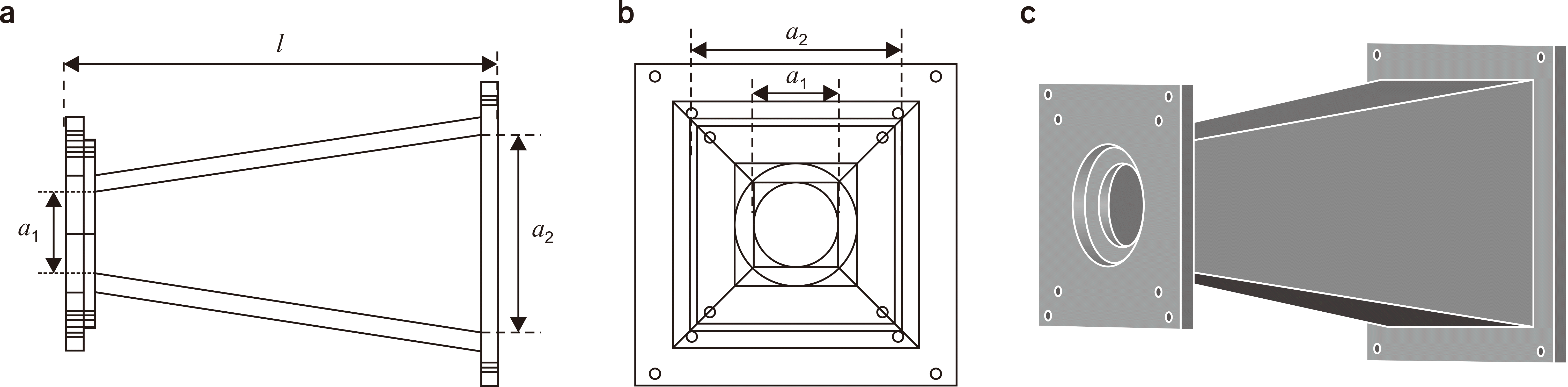
An interface slot, at the end of the collimator, was provided to connect an additional applicator at a later stage. A rail system was mounted in front of the irradiation device to move the sample, with 1 mm precision, in a straight line from SSD=40 cm to 100 cm. Here, the SSD is the distance from the source (scattering foil surface) to the sample’s surface.
The intensity of the electron beam, emitted from the exit window of the accelerating waveguide, depends on the operating parameters of the LINAC, such as the pulse frequency, pulse width, and heating current of the electron gun. Additionally, the dose rate is directly proportional to the average intensity of the electron beam but varies with the distance from the source. Moreover, the dose rate should be established as a function of LINAC parameters coupled with the SSD to develop multi-purpose irradiation systems. When the LINAC operates at a constant RF power and heater current of the electron gun, the dose rate (D) at an SSD can be expressed as,where D
ref is the dose rate (Gy/s) at a reference depth in water for the reference conditions of r=100 cm, f=100 Hz, and τ=2.5 µs. The reference depth is a point in the sample to which the dose is delivered and generally the depth of the maximum dose along the beam axis. s(r) is a distance-dependent function, where r is the SSD. Furthermore, p(f) and w(τ) are functions of the pulse frequency, f, and pulse width, τ, respectively. In case of an ideal LINAC, the beam intensity or dose rate is linearly proportional to the value of f and τ. However, our LINAC is not linear due to the combined characteristics of its components, such as the RF generator, high voltage devices, vacuum, and cooling system. Therefore, these functions should be determined experimentally. Various factors affect the dose rate in a LINAC based irradiator, making it difficult to evaluate the dose rate systematically. Fortunately, τ is fixed in the current system, as mentioned above; thus, here, w(τ)=1.
D
ref, s(r), and p(f) were determined to evaluate the irradiation system experimentally. If the modulator system changes, the w(τ) function can be recalculated to update the irradiation system.
3. Monte Carlo calculations
In this study, a thin stainless steel sheet was used as the material for the scattering foil, because the steel is not easily oxidized and is easy to process. While the thick foil increases the uniformity of the dose distribution on the irradiation field, it causes a significant energy loss. Therefore, the optimum thickness produces a uniform dose distribution in the field with low energy loss. However, it is known that dual foil produces more uniform dose distributions while maintaining the same energy loss as compared to single foil.
Owing to experimental difficulties, Monte Carlo calculations were used to determine the optimal foil thickness. The Monte Carlo N-particle extended (MCNPX) code supporting flexible geometric configurations was used in this study [11]. In the calculations, the initial electron beam energy incident on the scattering foil should be determined. Here, we determined the initial electron energy delivering, R
50, which coincided with the measured R
50 on the percentage depth dose curve through the measurement of the LINAC beam, and the calculations for 4.0, 5.0, and 6.0 MeV initial electrons. Both the measurement and calculations were performed with a scattering foil of thickness 0.15 mm in the polymethyl methacrylate (PMMA) phantom, at SSD=100 cm. As shown in Fig. 2, the initial energy for Monte Carlo calculations was 4.7 MeV. The electron energy used in the calculation was mono-energy of value 4.7 MeV, which was significantly different from the actual beam energy distribution. However, the measured R
50 was in a good agreement with the calculated R
50, as the difference between them was less than 0.1 mm.
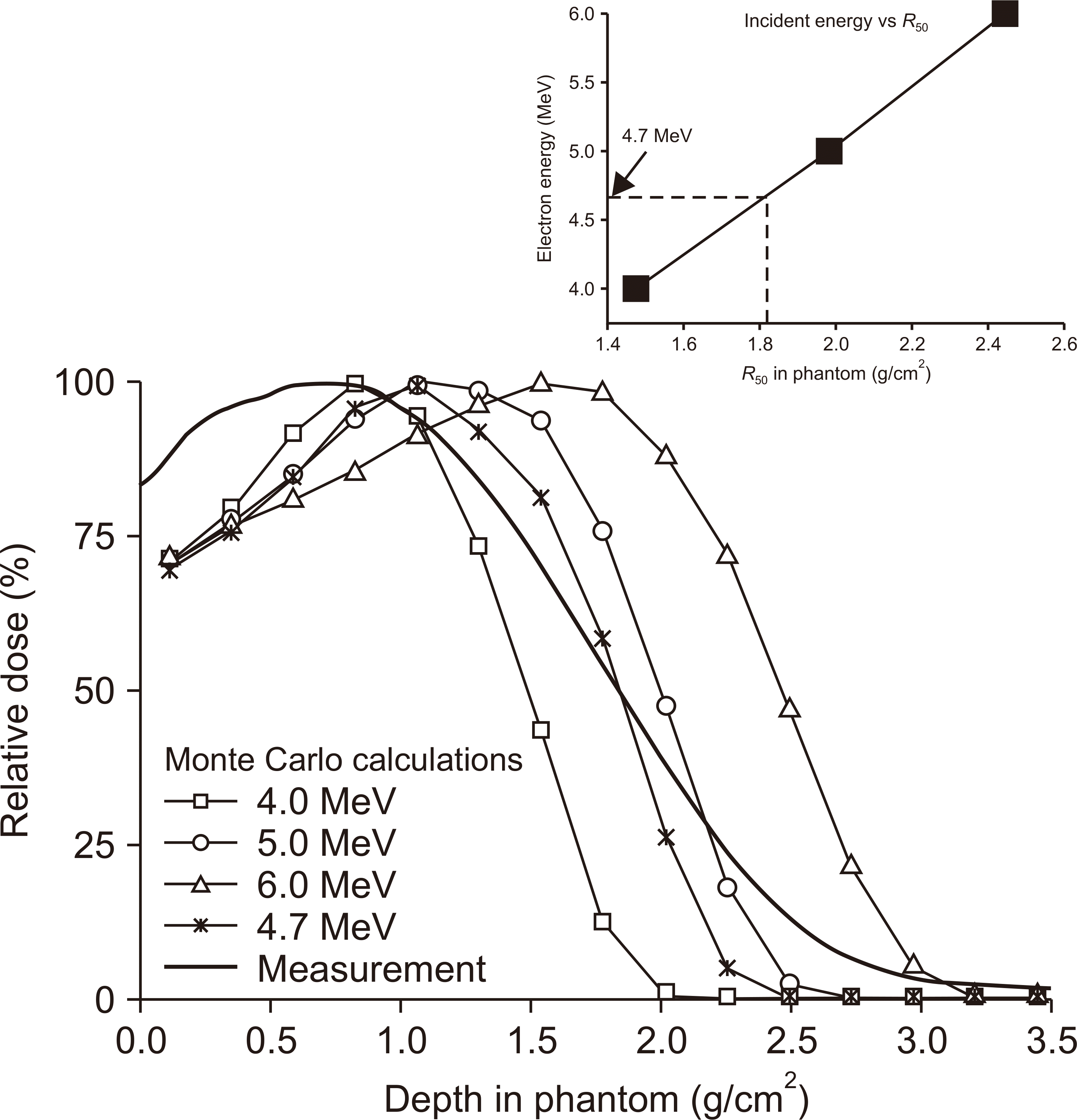
According to the IAEA dosimetry protocols, R
50 is the quality index of electron beams, and the mean energy at the phantom surface is determined by E
0=2.33R
50 [12]. This method is suitable for initial energy determination, and has been applied to Monte Carlo studies by Ding et al. [13].
Fig. 3 shows the geometry used for Monte Carlo calculations. The energy loss variation and beam profile uniformity were investigated. Moreover, we determined that the optimal thickness of the scattering foil was 0.3 mm for a single foil using this geometry. The determined single foil was replaced with a dual foil by dividing it into two foils with half the thickness to improve the uniformity of the beam profile. The dual foil was then applied to the experiments of the irradiation system [14]. Furthermore, Monte Carlo calculations were performed to verify the improvement of the beam profile uniformity at SSD=40 and 100 cm. The calculated results for these processes are described in the Results section of this paper.
The +F6 tally was used in our calculations to output the absorbed dose to the detector in MeV/g, along with the statistical uncertainty in the MCNPX calculation [11]. The statistical uncertainties were within 0.01 (1%) for 10 to 100 million histories at SSDs=40 to 100 cm. The cutoff energies of 50 and 10 keV for electrons and photons, respectively, were also applied during transport calculations.
4. Measurements
As mentioned above, D
ref, in equation (1), refers to the dose rate (Gy/s) under the reference conditions of SSD=100 cm, f=100 Hz, and τ=2.5 µs. Furthermore, the absorbed dose rate was measured using a calibrated ionization chamber (Advanced Markus, PTW Freiburg, Freiburg, Germany), positioned at a depth of 1 g/cm2 in the water phantom (T41023; PTW Freiburg, Freiburg, Germany).
The absorbed dose to water was determined by employing the IAEA TRS-398 dosimetry protocol [12]. Additionally, the ionization chamber was irradiated with electron beams characterized by 100 pulses using the pulse mode of the LINAC control system. The absorbed dose was determined using the average value of 5 measurements, where the operating pulse frequency was set to 100 Hz. Consequently, the single measurement time for the reference dose rate determination was 1 s.
s(r) is the relative dose with SSD along the beams axis. For the electron beams, the inverse square rule can be approximately applied for two doses located at a close distance. However, it is difficult to apply the rule to doses at SSDs ranging from 40 to 100 cm, used in this study. Therefore, the dose rates were directly measured and evaluated using the film dosimetry technique. The radiochromic film (Gafchromic EBT3; Ashland, Wayne, NJ, USA) was positioned at SSDs of 40, 50, 60, 80, and 100 cm. The measured values on films were normalized to that of SSD=100 cm and fitted using a logarithmic scale. For this measurement, the film was calibrated to 6 MeV electron beams at a depth of maximum dose at SSD=100 cm in the water phantom using the medical LINAC (Infinity; Elekta, Crawley, UK). Furthermore, electron beams were irradiated the calibration films with doses ranging from 100 to 1,000 monitor units (MU) at the dose rate mode of 400 MU/min. The irradiated films were analyzed using a scanner (1000XL; Epson, Long Beach, CA, USA) and software (FilmQApro; Ashland, Bridgewater, NJ, USA).
The function, p(f), represents the relative dose rates as a function of the pulse frequency of the LINAC. The dose rates were measured for pulse frequencies of up to 200 Hz at a depth of 1 g/cm2 in a water phantom using the ionization chamber, similar to that used for the dose rate measurement. p(f) was determined via two fitting functions using a normalized value for the pulse frequency of 100 Hz.
Go to :
Results
1. Monte Carlo calculations
The Monte Carlo calculated percentage depth doses (PDDs) and beam profiles at SSD=40 cm, as functions of the scattering foil thickness, are shown in Fig. 4. In these calculations, the energy of the incident electron was assumed to be mono-energetic 4.7 MeV, as previously discussed. In the given figure, as the foil thickness increases, the PDDs move toward the surface and beam profiles become more uniform. These properties are attributed to the energy loss and increased scattering of the electrons passing through the foil.
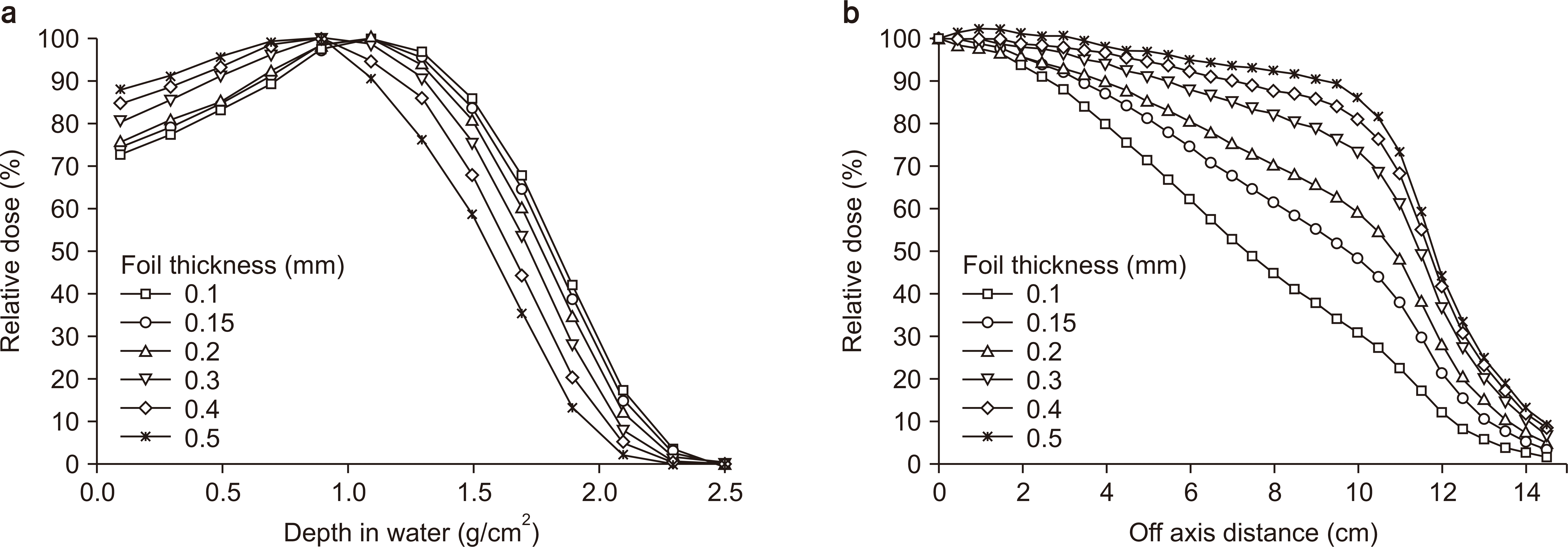
For the quantitative evaluation of energy loss, the mean energies at the phantom surface were calculated using R
50 depths, given in Fig. 4a, as E
0=R
50, the results of which can be found in Fig. 5a. The energy losses were approximately 0.1 MeV per 0.1 mm thickness within 0.3 mm foil thickness but increased to approximately 0.2 MeV for thicknesses greater than 0.3 mm.
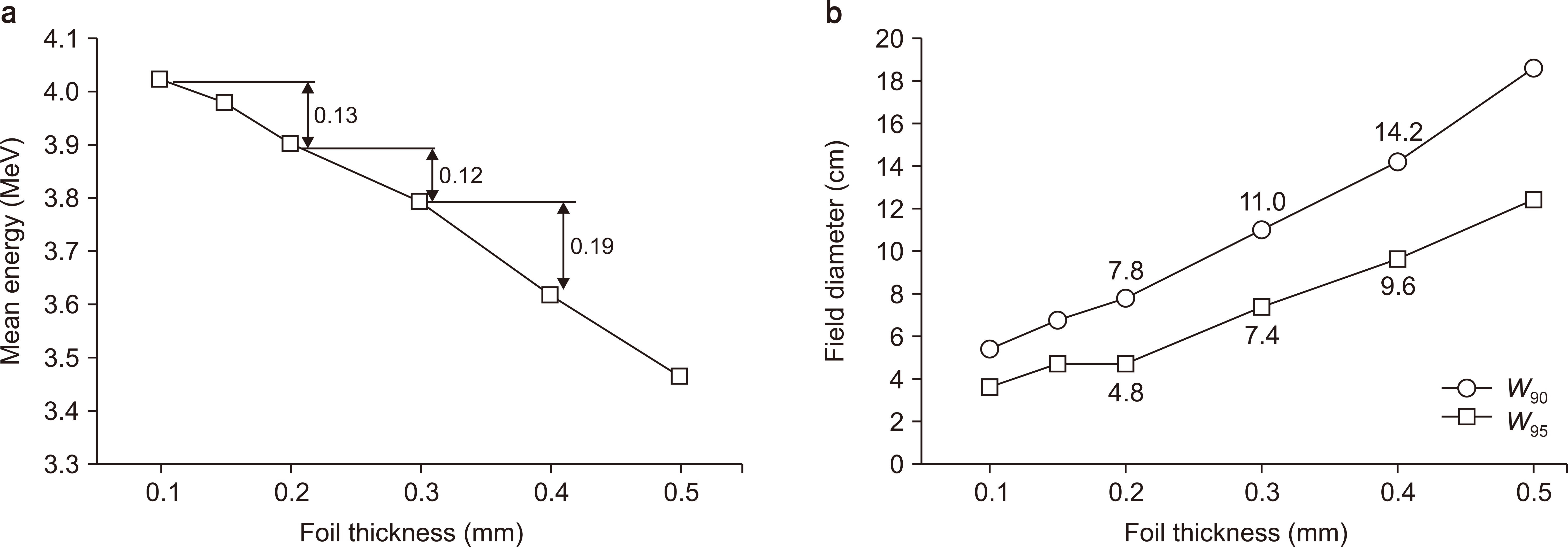
In the beam profiles, the W
90 and W
95 values were used to analyze the dose uniformity, as shown in Fig 5b, where W
90 and W
95 are the field diameters of 90% and 95% doses, respectively, compared to the central dose of the field. Here, W
90 and W
95 are the values for the irradiation system used in this study. In case of experiments on small animals, W
95 should be greater than 5 cm to deliver a uniform dose of 95% to 100%, relative to the central dose. This condition is satisfied for thicknesses greater than 0.3 mm, as shown in Fig. 5b, where W
95 for a 0.3 mm foil is 7.4 cm. Additionally, the size of adult mice is typically about 7.5 to 10 cm, and W
95 for a 0.3 mm thick foil is approximately close to that of the size of a small mouse for pre-clinical studies. W
90 can be used for large samples requiring dose uniformity within 10%. The calculated results are obtained at SSD=40 cm, which is the minimum SSD for this irradiation system. Moreover, the field diameter increases with increasing SSDs. Through these empirical analyses using the Monte Carlo calculated results, the 0.3 mm thickness was determined as the optimal thickness of the scattering foil in this study.
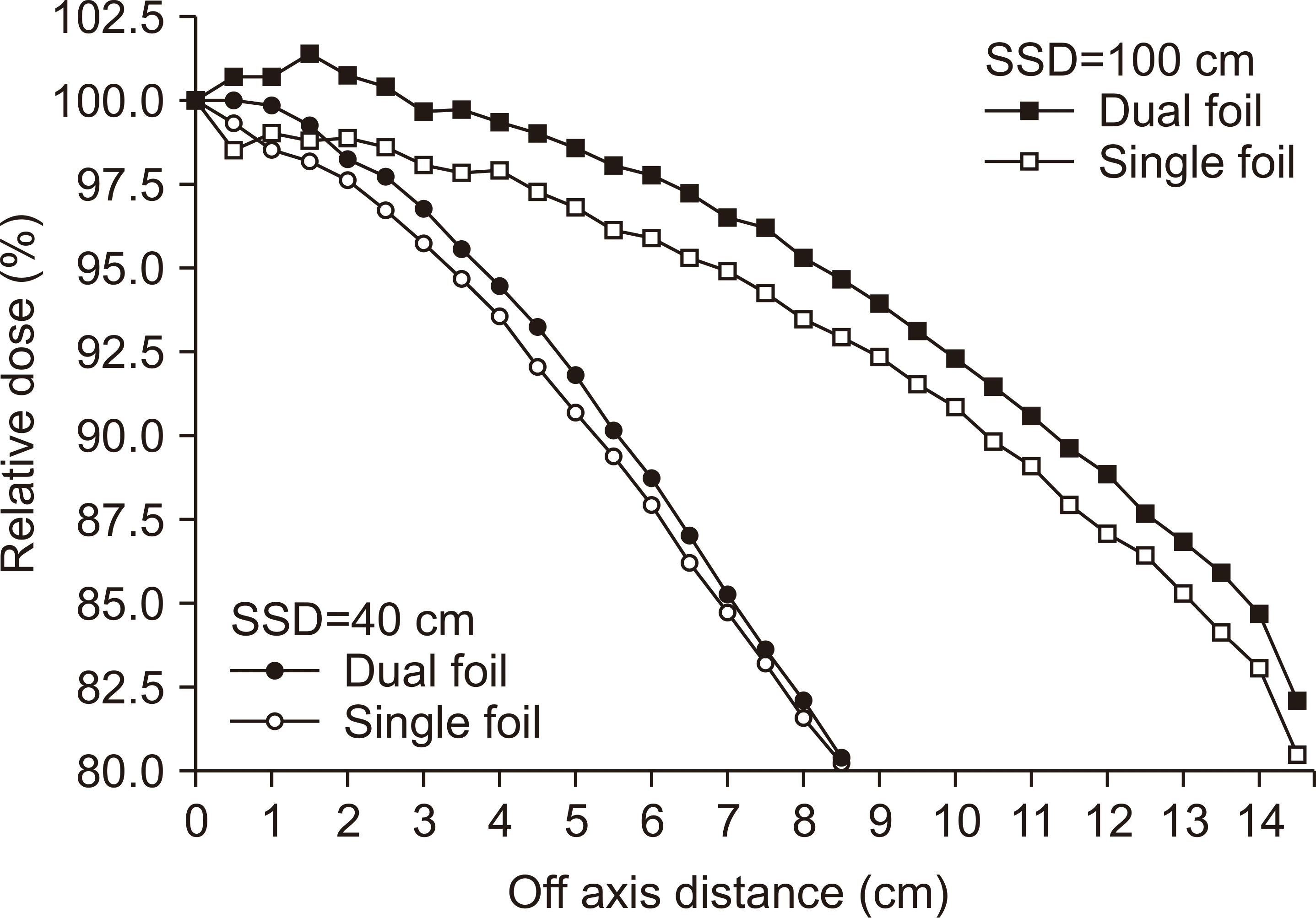
In practice, the dual foil was used in the irradiation system, wherein the foil was created by dividing the optimal-thickness single foil. The beam profiles for single and dual foils at SSD=40 and 100 cm were calculated, as shown in Fig. 6. The results of the dual foils for two SSDs were approximately 14% greater than those of the single foils, as shown in Fig. 6., which demonstrates that dual foils are more effective in producing uniform irradiation fields [14]. In the future, studies regarding the optimization of the thickness, shape, and separation of the foils should be considered.
2. Measurements
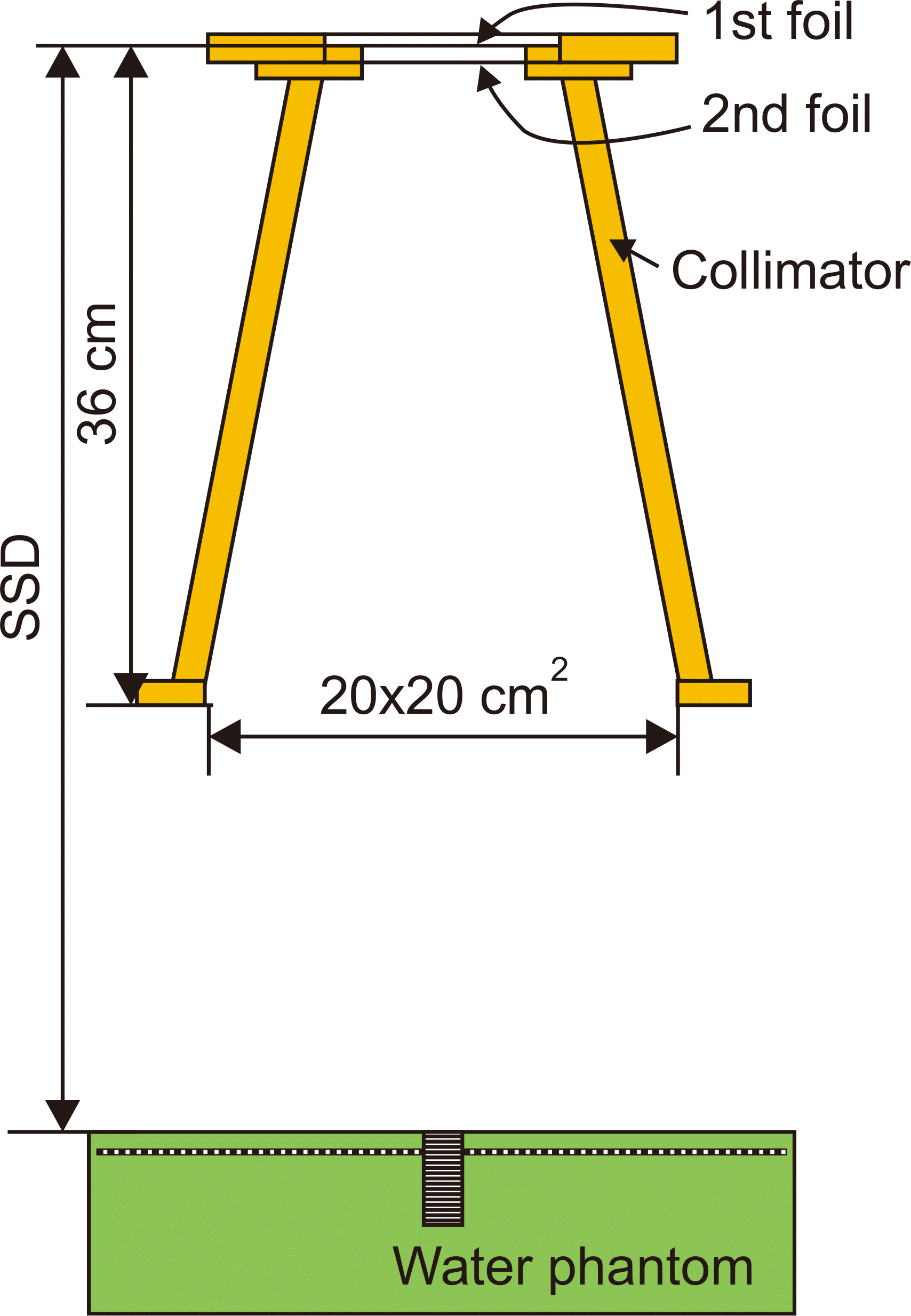
The measured results of D
ref, s(r), and p(f), used in equation (1), are described in this section. Fig. 7a shows the experimental setup for the reference dose-rate (D
ref) measurement using the ionization chamber. To apply the TRS-398 protocol, R
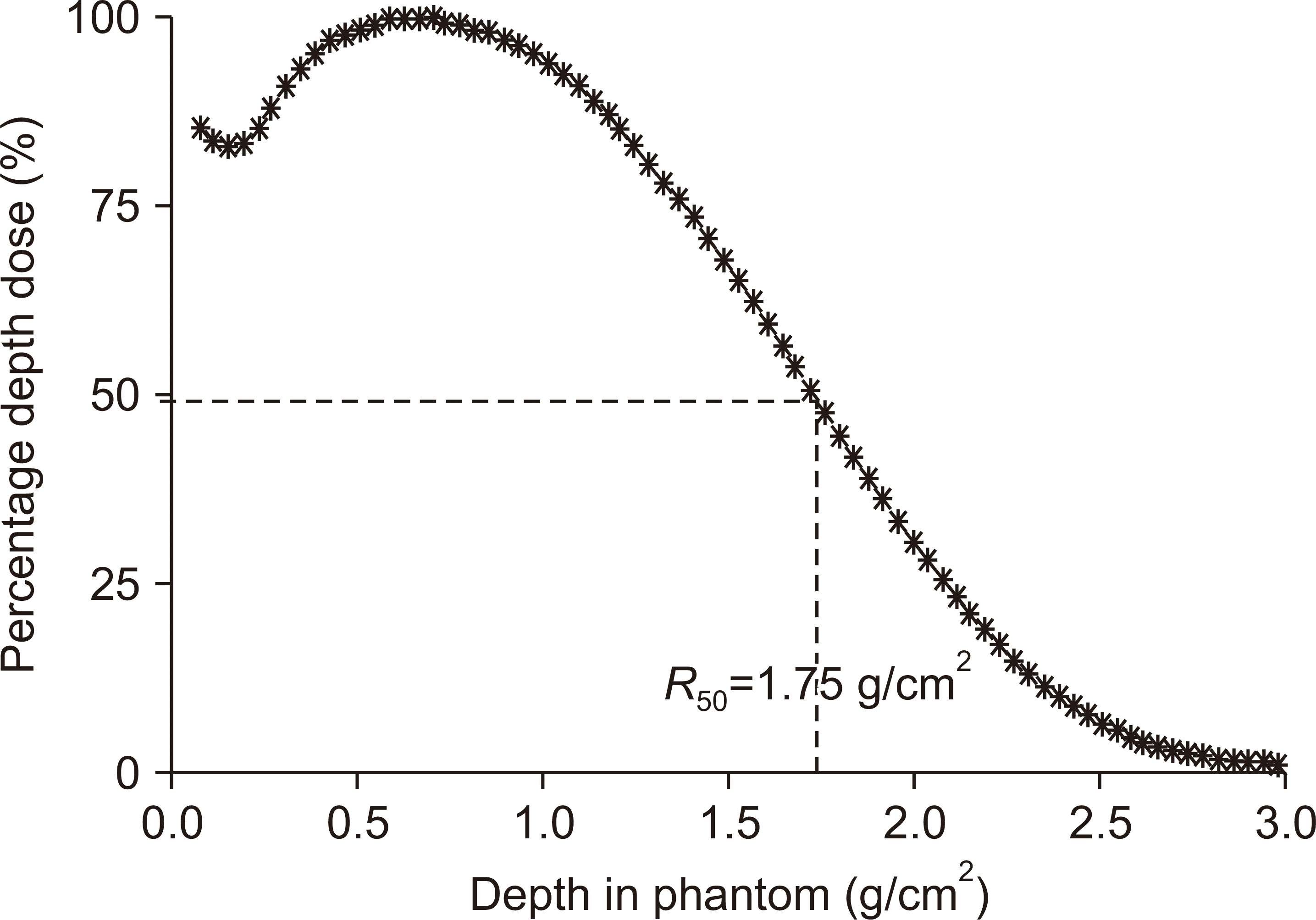
50 was determined via the normalized depth dose curve using film dosimetry in a PMMA phantom, as shown in Fig. 8 [12]. In this figure, the depth axis is the water equivalent thickness in g/cm2 using the scaling methods described in TRS-398 [12].

The measured results, using the ionization chamber, are summarized in Table 1. Additionally, the dose rate was 7.156 Gy/s at a depth of 1 g/cm2 in water. In the irradiation system, in general, the reference depth in the sample is set to the depth of maximum dose in water. The value can be converted by using the measured percentage depth dose data, and the estimated dose rate at the maximum depth was 7.573 Gy/s, as described in Table 1. Furthermore, we set the value as D
ref in equation (1). The relative standard uncertainty (1σ) in this measurement was estimated to be approximately 1.4% from the statistical summation of the ionization chamber calibration factor (0.7%), charge measurement (0.6%), correction of charge (0.2%), quality factor (1.0%) and other variables (0.5%).
Table 1
Measured reference dose rate in water using TRS-398 dosimetry protocol
![]()
In Table 1, the pulse per dose refers to the dose for an electron beam pulse. If the dose per pulse is higher than approximately 0.1 Gy/s, ion-recombination corrections are required for the result of the ionization chamber [8]. Therefore, we employed film dosimetry for the measurement of various SSDs, and the dose rates between SSD=40 and 100 cm were derived from the results of the ionization chamber dosimetry at SSD=100 cm. In addition, an objective of this study was to evaluate the possibility of FLASH research using the proposed LINAC system. Therefore, the optimization of the scattering device was performed at SSD=40 cm.
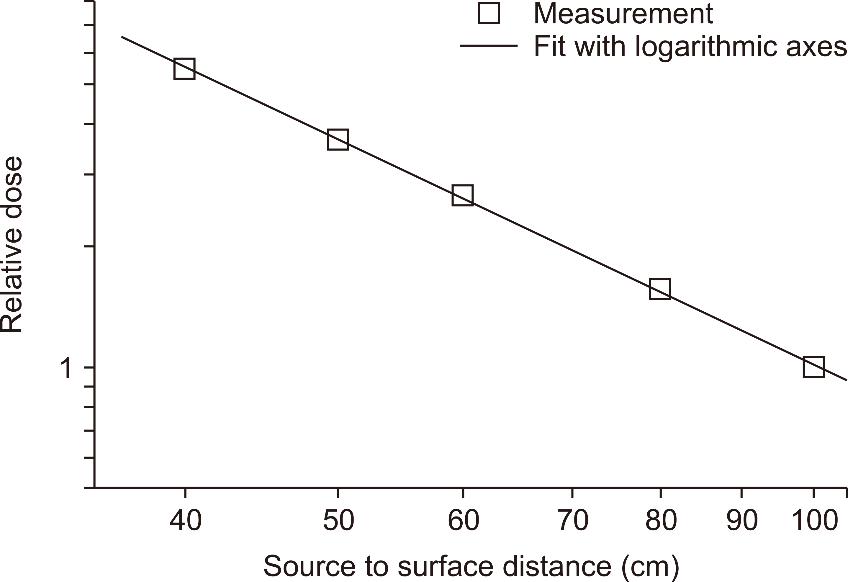
Fig. 7b shows the experimental setup using radiochromic films. The films with an area of 14¡¿14 cm2 were positioned at a depth of 1 cm in the PMMA phantom. The doses at the central and peripheral regions of the film were used to determine the relative dose rates and beam profiles at the SSDs. The measured relative doses and fitted values are shown in Fig. 9. The derived function of the SSD, s(r) is,where, u
1=3.699 and u
2=–1.849.
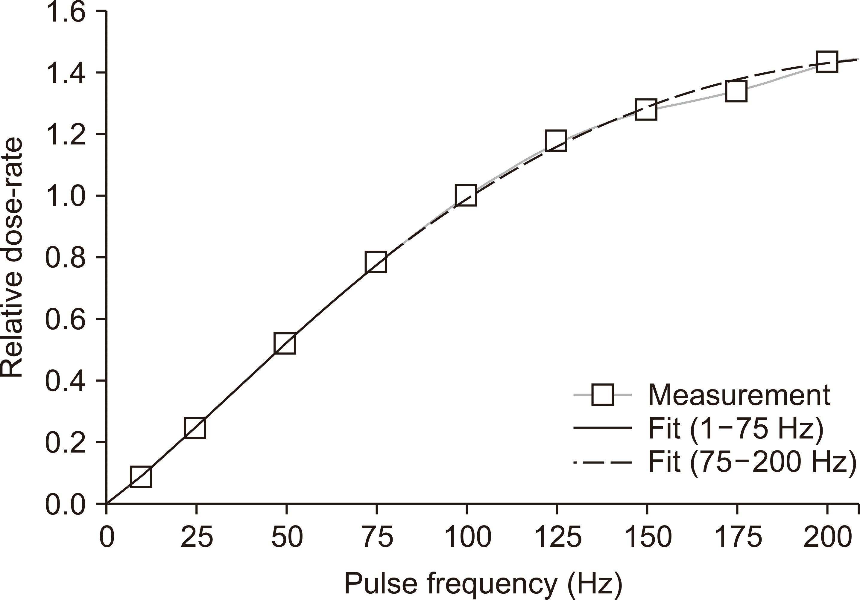
The relationship between the pulse frequency and dose rate is shown in Fig. 10. The measured values were obtained using the Markus ion-chamber positioned at 1 g/cm2 in the water phantom at SSD=100 cm. The normalized doses for the dose at f=100 Hz were fitted using linear and polynomial functions over the frequency ranges as follows, where, g1=–0.00964, g2=0.0106 Hz–1, g3=–0.05982, g4= 0.01358 Hz–1 , and g5=–3.060¡¿10–5 Hz–2. The dose rate was approxi¡©mately linear up to 100 Hz and slowly increased up to 200 Hz. As previously mentioned, the properties depend on the performance of the LINAC components, such as the pulse modulator and RF generator. When replacing the components, equation (3) should be updated via measurements in terms of quality assurance of the irradiation system.
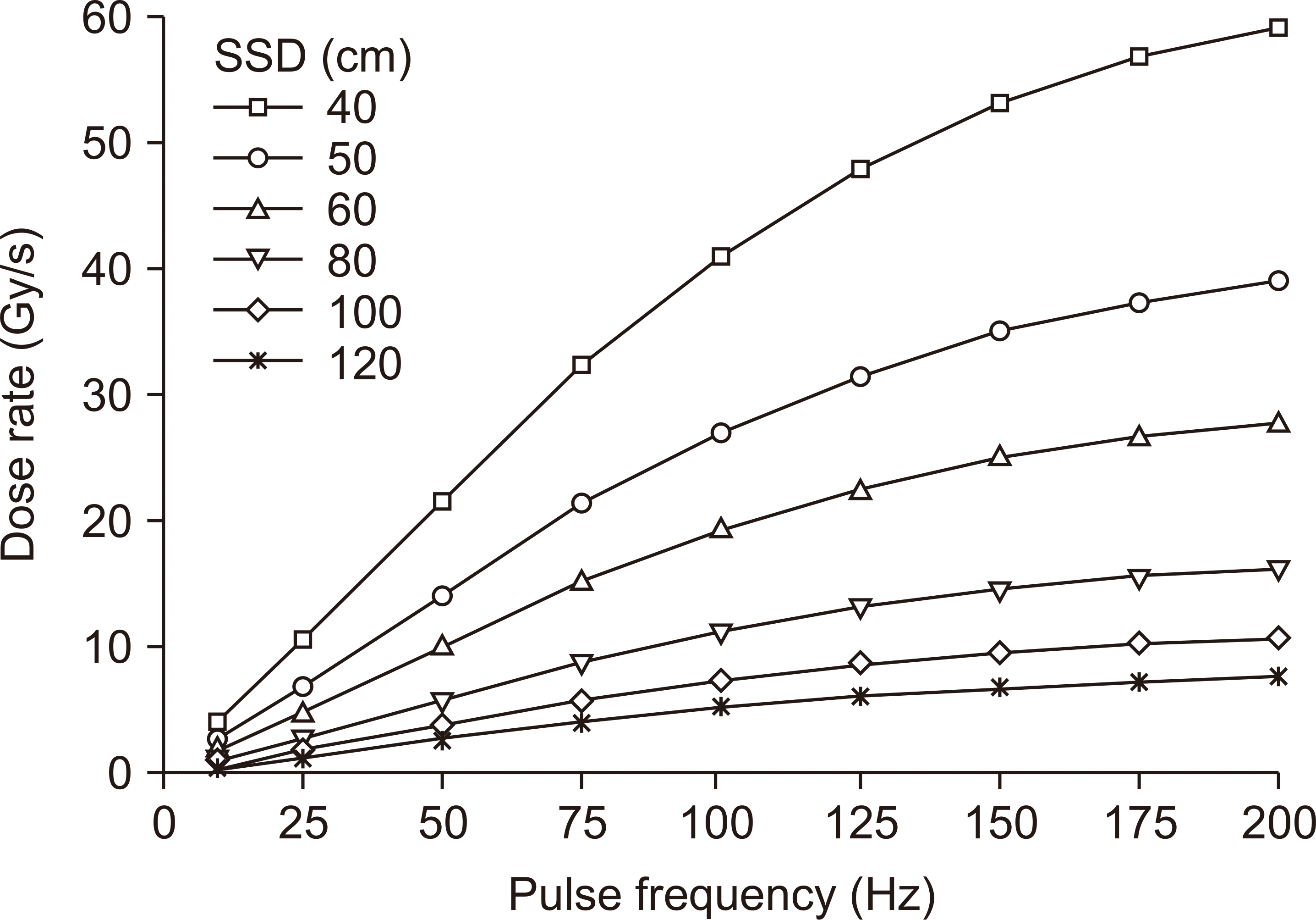
From the determined values of D
ref, s(r), and p(f), the dose rates in Gy/s as a function of SSD and pulse frequency can be determined, as shown in Fig. 11. The values in this figure were recorded at a depth of maximum dose in water. Since the sample can be positioned at the extended SSD over 100 cm in the irradiation room, the dose rate evaluation was performed for up to 120 cm, as shown in Fig. 11. The result shows that the maximum dose rate for this irradiation system is 59.16 Gy/s at 200 Hz. If a low dose rate is required, the dose rate can be reduced to 0.0522 Gy/s (5.122 cGy/s) at an SSD=120 cm under 1 Hz operation.
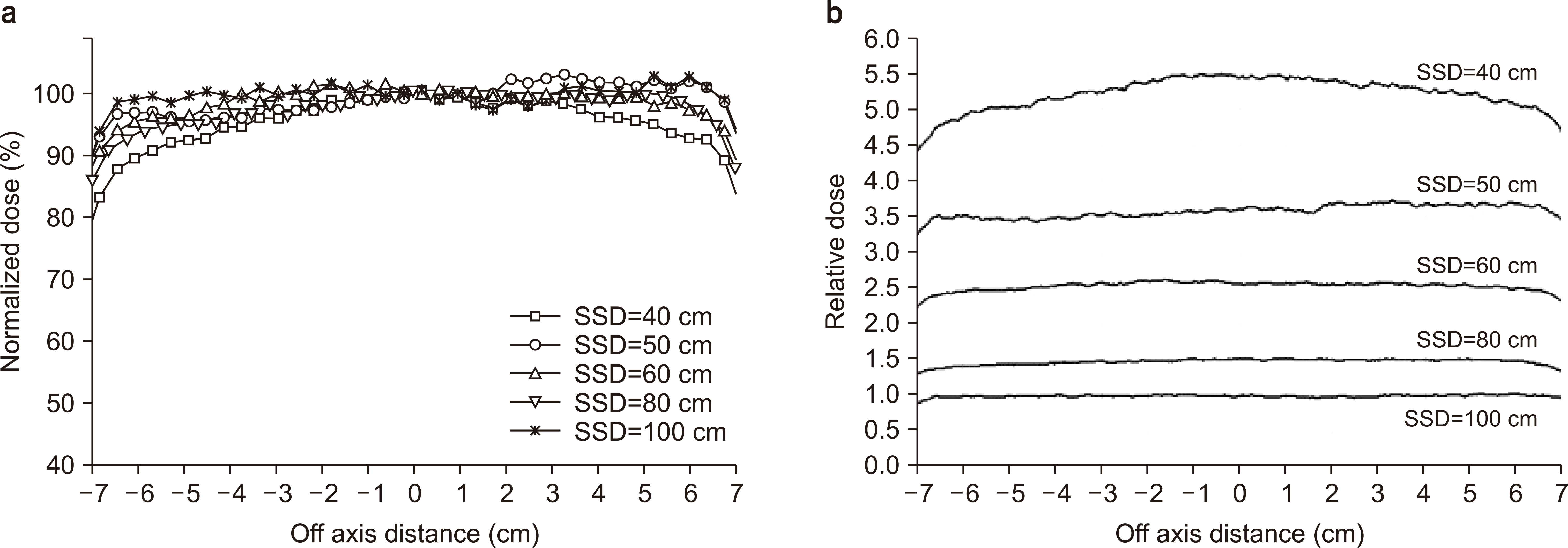
The measured beam profiles, normalized at the central dose, are shown in Fig. 12a and those normalized at the central dose of SSD=100 cm can be found in Fig. 12b. When evaluating the beam profiles, the W
95 value at SSD=40 cm was 8.8 cm, and the W
95 values at other SSDs were greater than 12 cm. However, current devices pose a challenge in producing a uniform irradiation field for diameters above 15 cm. Thus, an additional applicator may be required. In the future, a study on suitable applicators to improve the irradiation system will be conducted.
Go to :
Discussion
In this study, the dose rate, as a function of SSD and pulse frequency for a developed irradiation device, was evaluated to establish a multi-purpose electron beam irradiation system using a research electron LINAC. Since many electron-beam characteristics, including energy, dose rate, and beam profile, depend on the thickness of the scattering foil, the process of determining the thickness of the scattering foil using the Monte Carlo calculation was further complicated. Here, the characteristics of the electron beams, emitted from the scattering device, vary according to several factors, such as the incident beam energies, materials, and thicknesses of the foils, and collimator geometry. Therefore, we simplified the problem by empirically observing only energy loss and beam uniformity as functions of thickness for a given geometry using Monte Carlo calculations. Throughout this research, only steel sheets were used as the scattering foil. However, other foil materials possessing three-dimensional geometry should be studied for the improvement of beam profile uniformity while minimizing the energy loss of the electron beams.
By using the pulse frequency control function of the LINAC, the sample can be irradiated by electron beams having a dose rate of up to approximately 60 Gy/s at an SSD of 40 cm. Additionally, it is possible to irradiate the electron beams with a dose rate at the cGy/s level by reducing the pulse frequency and increasing the SSD. At nearly SSD=100 cm, the dose typically varies according to the SSD for the electron beams generated using the clinical LINAC, which follows the inverse square function and can be determined by an effective SSD method [15]. However, since this irradiation system supports wide SSDs ranging from 40 to 120 cm, the fitting function was determined using the log-log plot. This method is generally used for irradiation systems in calibration laboratories [16]. Moreover, the dose distribution in the irradiation field was evaluated. Since the electron beams can uniformly irradiate a sample with a 12 cm diameter with a range of 5%, except for SSD=40 cm, we can perform pre-clinical studies using small to medium animals or cultured cells as well as material studies on semiconductor devices and sensors. In case of SSD=40 cm, samples less than 8 cm in diameter can be irradiated with a high dose rate greater than 50 Gy/s.
From the measured depth dose data, the mean energy of the actual beam at the phantom surface is estimated to be 4.08 MeV. This value is higher than the Monte Carlo calculation result for 0.3 mm foil using the mono energy of 4.7 MeV, as shown in Fig. 5. It is believed that the actual beam contains high energy components in the energy spectrum. Moreover, as measured, the maximum dose depth is 0.7 cm. Therefore, the depth at which the dose is delivered in the sample should be considered. If a thin foil is used, the average energy and dose rate of the electron beams increase. However, the uniformity of the dose distribution decreases. Thus, optimizations of foils and applicators to produce large uniform fields should be pursued for further studies.
This study focused on the development of an irradiation device using a developed electron LINAC. In addition, the LINAC operates according to a similar principle as that underpinning the clinical LINAC. However, the current system differs from a clinical LINAC in terms of beam energy, auxiliary control system, and performance. Nevertheless, as high-energy-accelerating waveguides, precise RF, high-voltage control systems, and beam monitoring devices are being developed, this LINAC will provide similar performance to clinical LINACs in the future.
Go to :
Conclusions
Through this study, we developed a multi-purpose electron beam irradiation device. The LINAC was constructed for research and development of radiation therapy machines, but can also be used in clinical and industrial fields. Notably, the LINAC has a similar specification to that of the clinical LINAC; therefore, pre-clinical experiments for cancer research are available. In addition, this study revealed that dose rates close to the collimator exit are greater than 40 Gy/s; thus, pre-clinical studies of FLASH-RT are also possible with this system. Further studies will be performed to improve the energy, dose rate, and field uniformity of the irradiation system.
Go to :
 XML Download