

 PDF
PDF ePub
ePub Citation
 Print
Print


INTRODUCTION
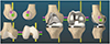
Hip–knee–ankle angle was defined as the medial angle formed by the axes that pass through the center of femoral head, the midpoint between the tips of tibial spines, and the center of superior facet of the talus. Mechanically aligned total knee arthroplasty (TKA) strives to achieve a neutral mechanical alignment of the limb (0° hip–knee–ankle angle), as well as a varus–valgus alignment of the tibial component perpendicular to the tibial mechanical axis in all subjects. Malalignment leads to decreased functional outcomes, and it also has been related to early failure due to wear and loosening.1234 Although mechanically aligned TKA improves function, about 20–25% of TKA patients tend to remain dissatisfied.567 Interestingly, this issue has not been solved either by computer-assisted surgery and robotic technology to improve implant positioning or by continuously improving implant designs. On the contrary, there is a weak relationship between the alignment (in-range, varus and valgus outlier groups) of the limb and the survival of implant and clinical outcomes of primary TKA.89101112131415 For these reasons, a different technique is needed to align a TKA performed with the goal of improving patient's function and restoring more natural kinematics, “natural alignment, not neutral alignment.”
The kinematically aligned TKA aims to achieve the optimal function of the patient's knee by resurfacing the femur and tibial articular surfaces with those of pre-arthritis while causing minimal damage to the surrounding tissues and ligaments. Kinematic alignment has grown in interest in recent years due to a number of randomized trials, and a national multicenter study reported that patients treated with kinematic alignment showed significantly better pain relief, function, and a more natural-feeling knee than for those who were treated with mechanical alignment.16171819202122 Furthermore, Howell, et al.23 recently reported a high survival rate for kinematically aligned implants at 10 years.
The precise implementation of the three key axes (primary and secondary femoral flexion axes and longitudinal tibial axis) for kinematically aligned TKA with conventional instruments is very complex and limited in the arthritic knee. To overcome these complexity and limitations, patient-specific instrument (PSI) has been used to implement kinematic alignment. PSI has been developed as a new technology to pursue the same goal of navigation in improving the accuracy of surgical technique and avoiding the practical issues related to the high cost and complexity of the navigation and robotic system, such as higher number of personnel required, longer surgical time, and the learning curve related to the procedure. With the development of a three-dimensional (3D) printing technique, PSI can be easily and simply manufactured in local manufacturing facilities at a much lower cost, and the time procured to these customized instruments has been reduced to less than a week. Later in this article, the manufacturing and surgical process of our home-made PSI will be introduced, which is registered under the Korean Ministry of Food and Drug Safety.
HISTORY OF PSI WITH KINEMATICALLY ALIGNED TKA
Kinematically aligned TKA with PSI was first performed in January 2006, and over 17000 cases were performed in the United States between 2006 and 2009. Howell, et al.24 showed the initial experience of one surgeon using PSI (OtisMed) in 48 knees; among them, 45 of the femoral and tibial cutting guides fit securely. The poor fit of the three femoral and tibial guides was discovered retrospectively as the result of a technical error in aligning the magnetic resonance imaging (MRI). Using PSI, the sizes of implanted components matched up to the expected size of femoral and tibial components in every knee. In 2008, the risk for malalignment with PSI (OtisMed) was reported by Klatt, et al.,25 based on navigated measurements of alignment in just four subjects without clinical follow-up. In September 2009, the Food and Drug Administration (FDA) did not approve the use of patient-specific guides to implement TKA. Recently, Howell, et al.23 reported that the implant survivorship (yearly revision rate) of kinematically aligned TKA with PSI was 97.5% (0.3%) for revision due to any reason and 98.4% (0.2%) for aseptic failure. Postoperative alignments of the tibial component and limb did not affect implant survival or the mean Oxford Knee Score and WOMAC scores.23 In November 2018, PSI for kinematically aligned TKA was approved again by the FDA.
PRINCIPLE OF KINEMATICALLY ALIGNED TKA
The basic principle of kinematically aligned TKA is to restore the patient's pre-arthritic state and kinematic axes of the knee. Kinematic studies of the natural knee have confirmed a single radius and single axis (primary femoral axis, cylindrical axis) for the posterior femoral condyles.262728 In other words, the primary femoral axis remains equidistant from the surface of both posterior femoral condyles.2629 In order to perform kinematic alignment, three kinematic axes must be applied depending on the predicted articular surface prior to arthritis. The most important kinematic axis passes through the center point of the best-fit circle of medial and lateral femoral condyles, and is termed the primary femoral axis (primary cylindrical axis). This axis determines the position of femoral component about which the tibia flexes and extends. The basis for restoring normal kinematics in TKA is alignment of the axis of femoral component with the primary femoral axis of the knee. There is a substantial difference between the primary femoral axis and transepicondylar axis equidistant from the surface of posterior femoral condylar surface. The primary femoral axis is more valgus and more internally rotated compared to the transepicondylar axis.28 A secondary femoral axis is the transverse axis in the femur and is oriented parallel, proximal, and anterior to the primary femoral axis, and the patella flexes and extends around this axis. A third tibial axis is the longitudinal axis in the tibia, perpendicular to both the primary and secondary femoral axes, about which the tibia rotates on the femur internally and externally (Fig. 1).282930
PREOPERATIVE PLANNING FOR MANUFACTURING A PSI
Reconstruction of 3D model
Using an 80-channel computed tomography (CT), 1-mm-thick CT images of the hip, knee, and ankle are obtained preoperatively in the patient. A 3D medical image processing software is used to generate a 3D bone model of the lower extremity, including the femoral head, knee, and ankle. There are benefits and drawbacks of both CT and MRI scans for manufacturing PSI. CT scan is quick, easy to access, and provides better anatomical bone details, but is associated with increased exposure to radiation. MRI has the advantage of being able to measure articular cartilage.3132 Since the extent of cartilage damage in arthritic knee varies by region, cartilage thickness information is very important for secure PSI positioning. However, MRI also has some disadvantages, as it is associated with increased scanning time, claustrophobia, and higher cost, and cannot be used if there are metallic objects in the same or opposite limb.
There have been various results of the accuracy between CT- and MRI-based PSI. Pfitzner, et al.33 reported that MRI-based PSI was more accurate than CT-based PSI regarding the coronal mechanical limb axis, although differences were subtle and of questionable clinical relevance. Ensini, et al.34 compared MRIbased PSI TKAs with 25 CT-based PSI TKAs, and found no difference in the coronal alignment.
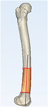
Preoperative determining of distal femoral flexion axis
The femur is divided into three parts from the head to distal femoral joint line. From the upper margin of the distal one-third of the femur to metaphyseal flare, dots are marked (registered) with a pen forming a truncated cone. The distal flexion axis obtained from the best-fit line passes through the center of truncated cone (Fig. 2). Nedopil, et al.35 reported that patella instability occurred in 4% of patients undergoing kinematically aligned TKA with conventional instruments, which was associated with greater flexion of the femoral component (11° vs. 5°; p=0.0012). Therefore, minimizing the flexion of femoral component could reduce the risk of patellofemoral instability by promoting early engagement of patella in the trochlear during knee flexion. To avoid patella instability, we set the boundary below 11° for the difference of angle between distal femoral flexion axis and diaphyseal axis on sagittal plane. The measurement method for determining axes was described in the author's previous article.36
Preoperative determination of primary femoral axis
The surfaces of distal femoral condyles were marked from the condylar sulcus to the posterior end of posterior condyles. The best-fit sphere was made from registered points, and putative positioning sphere's center was equidistant from pre-arthritic articular surface. Primary femoral axis was made by connecting the centers of two spheres (Fig. 3). Howell, et al.37 reported there is no clinically relevant asymmetry between the radii of the best-fit circles of medial and lateral femoral condyles in varus and valgus osteoarthritic knees in the Western population (≤0.2 mm).
Distal and posterior femoral bone cuts are equal in thickness to the respective regions of femoral component in the kinematically aligned TKA. Distal and posterior femoral bone cuts can be performed using reference to the articular surface or primary femoral axis. Although the articular surface-based bone cut is commonly used in kinematically aligned TKA using conventional instruments, it is also used in PSI-guided kinematic TKA. In the articular surface-based bone cut, posterior reference plane was made as a plane that included a tangential line connecting the most posterior points of medial and lateral femoral condyles. Distal reference plane was made parallel to the posterior plane, including a tangential line connecting the most distal points of medial and lateral femoral condyles. In the primary femoral axis-based bone cut, distal and femoral bone cutting was performed at the same distance from primary femoral axis. Distal bone cutting was perpendicular to distal femoral flexion axis and parallel to primary femoral axis. Niki, et al.7 compared the accuracy of the primary femoral axis based on bone cut and articular surface-based bone cut, and concluded that the primary femoral axis-based bone cut is preferable to the articular surface-based bone cut for reproducing the primary femoral flexion-extension axis.
Preoperative determination of tibial alignment (varusvalgus and posterior slope)
A kinematic tibial cut is determined to be parallel to the articular surface of proximal tibia, defined by the plane of best fit to both plateaus (overall arthritic plateau).38 The registration process involves a surface centroid, excluding the surface of meniscus and tibial spines (Fig. 4). Nedopil, et al.39 reported that the tibial component failure after kinematically aligned TKA was 0.3%, and was caused by posterior subsidence or posterior edge wear and not varus subsidence. They also reported that tibial component failure group had a 5° greater posterior slope (mean 11.2°±3.1°, p=0.002) than the corresponding control group (mean 6.0°±2.7°).
Preoperative determination of guide pin location
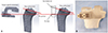
Some PSI provides options for locating pins and bone cutting in one piece, and offers a complete single-use instrument set for TKA. This system is designed to improve logistics and instrument management, offering substantial logistical and financial benefits in the surgery room and throughout the supply chain of hospitals. After locating the pins for bone resection, some PSIs use the pin positions for sitting separate conventional cutting blocks (Fig. 5). PSI is designed to fit into the arthritic knee of each patient in only one specific position for accurate and secure fixation. Pin locations are determined according to pre-planned kinematic alignment and bony resection thickness, using a computer software (Fig. 5).
SURGICAL TECHNIQUE
The anterior-posterior (A-P) offset, which is the distance between distal medial condyle of the femur and anterior cortex of the tibia at 90° of the flexion of the knee, is measured before distal femoral resection (Fig. 6). PSI is seated and secured to its unique position on anterior surface of the femur. Since CT-based PSI does not take into account the thickness of the remaining cartilage of the worn area, it is necessary to remove the remaining cartilage completely from the footprint of articular surface contacted by PSI. After PSI is removed, distal cut is made through a distal cutting guide, which is attached at two pin locations made of a PSI when using separate types. Next, the remaining femoral cuts are made by a chamfer guide, which is attached to two other pin locations made from a PSI on distal surface of the femur. For tibial cutting, PSI is seated and secured to its unique position on the articular surface of tibia. After PSI is removed, the tibia is cut with a cutting jig, which is attached at two pin locations made of a PSI when using separate types. The posterior cruciate ligament is preserved for more natural knee kinematics. A manual instrument technique is used to set the internal-external rotation of anterior-posterior axis of tibial component parallel to the major axis of an ellipse drawn on lateral tibial condyle.4041 Balance of the knee and patella tracking is assessed qualitatively by manual and visual examinations. When an asymmetric laxity in coronal plane is observed, the 2° varus or valgus re-cut guide is used to finely tune the tibial resection until the laxity is 1° or less like the native knee. When the difference of an A-P offset is observed after inserting trial implants, posterior slope and thickness of the tibial component is adjusted until the A-P offset matches that of the knee at the time of exposure (Fig. 6). A step-wise algorithm is used for balancing the kinematically aligned TKA (Table 1).
SELECTION OF THE IMPLANT TO PERFORM KINEMATICALLY ALIGNED TKA
Kinematically aligned TKA with an implant for mechanical alignment
Kinematic and mechanical alignment techniques have different philosophies, but most kinematically aligned TKAs use implants for mechanical alignment. The intended settings of the femoral component for mechanical alignment are 3° to 5° external rotation relative to posterior condylar axis or transepicondylar axis. Femoral components for mechanical alignment are designed to maximize the proximal and lateral reach of the trochlea in order to promote early patella involvement, more normal patellar tracking, and even the distribution of contact stress on the patella.42434445 When performing kinematically aligned TKA with an implant for mechanical alignment, femoral trochleae is substantially under-stuffed with reduction in lateral reach, and it becomes more valgus than native trochlea.1846 It is correlated with abnormal patellar tracking and an uneven distribution of contact stress on the patellar component.47 There is another concern regarding mid-flexion instability in kinematically aligned TKA with implant for mechanical alignment. Incavo, et al.48 reported that kinematically aligned TKA demonstrated mid-flexion lateral joint space opening and late-flexion medial opening. Therefore, it is important to design an implant with the optimal shape for restoring natural knee kinematics that might improve patient-reported satisfaction and function.
Medial stabilized design implanted with kinematic alignment restores higher function, and offers better anterior stability than anterior cruciate ligament (ACL) and partial meniscal deficient designs
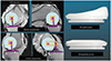
A promising strategy for kinematic alignment, which aims to restore high function and anterior stability and also reduce the risk of late tibial component failure from posterior rim wear of the insert, is to use a medial stabilized (MS) implant design with an insert consisting of a medial ball-and-socket and a lateral flat surface without a posterior rim (Fig. 7).49505152 In medial compartment, the insert should have a near 1:1 ball-and-socket conformity to promote A-P stability like the native knee. In lateral compartment, the insert should be flat without a posterior rim to enable internal-external (I-E) rotation of the tibia on the femur like the native knee.51 An insert without a posterior rim replicates the loss of constraint resulting from the lateral meniscus rolling off the posterior tibia when the knee is in deep flexion, and reduces the risk of instability from posterolateral rim wear.50
The benefits of the MS design were reported in a single surgeon randomized trial which showed that the functional outcomes of patients who were treated with MS design (SAIPH) (n=53) were better than those treated with ACL and partial meniscal deficient designs (Vanguard CR) (n=50) implanted with kinematic alignment principles.50 Patients who were treated with MS design had a 16-point higher self-reported Forgotten Joint Score than those treated with ACL and partial meniscal deficient designs. The mean 80-point score of MS design is comparable to that of total hip arthroplasty.51 The greater anterior stability and more normal I-E rotation provided by MS design explains its higher function compared to ACL and partial meniscal deficient designs.51
CONCLUSION
Kinematically aligned TKA is a new alignment technique for restoring natural tibial-femoral articular surface, alignment, and natural laxity of the knee. This alignment technique has shown promising implant survival at 10 years, as well as improved pain relief, function, and a more natural-feeling knee than treatment by mechanical alignment. In order to successfully perform the kinematically aligned TKA, three kinematic axes must be correctly implemented. However, the implementation of these axes using conventional instruments is complex and limited. PSI, designed to make surgery more simple and accurate, is a useful tool for implementing the kinematically aligned TKA.


 XML Download