

 PDF
PDF ePub
ePub Citation
 Print
Print


INTRODUCTION
Implant-supported fixed dental prosthesis (FDP) is a welldocumented treatment option for partially or completely edentulous patients. FDP enhances the masticatory function, as well as esthetics, and has high success and survival rates.12 Implants are conventionally retained using screws or cement, and FDP has advantages and disadvantages associated with cement remnants, screw hole creation, and retrievability.3456789
Screw retention avoids the problem of cement remnants and allows good retrievability; however, it requires the creation of a screw hole on the occlusal surface. Although the hole can be filled with composite resin, microleakage can occur if the occlusal contact point is on the filled resin.10 The hole occupies a portion of the occlusal table and the occupied proportion is higher when the occlusal table area is small.11 Additionally, positioning of the screw on the labial surface of incisors leads to esthetic problems.1213
Cement retention is associated with occlusal integrity; however, it is not easy to ensure that the cement remnants have been completely removed from the subgingival area.311 The problems with cement remnants and retrievability are the main drawbacks of cement-retained (CR) implant prostheses. Cement remnants could accumulate in the subgingival area even after a thorough removal process1415 and lead to peri-implantitis.3 CR implant prostheses were also reported to demonstrate relatively poor retrievability.16
A novel retentive type of implant prosthesis that does not require the use of cement or screw holes has been introduced. Cementless fixation (CLF) provides a precise fit between the implant crown and the abutment because the inner surface of the implant crown is relined using flowable composite resin during the fabrication process. CLF requires a sunken structure on the occlusal surface of the abutment called the air hole, which is created to evenly distribute stresses over the occlusal surface. However, there are few reports examining the biomechanical aspects of the CLF implant crown. The optimal design for decreasing the stress distribution on the CLF implant crown has not yet been studied. This study aimed to evaluate the biomechanical features of the different designs of CLF implant crowns through finite element (FE) analysis, including stress analysis, gap formation on the faced interfaces, and strain analysis of the surrounding peri-implant bone.
MATERIALS AND METHODS
Three-dimensional (3D) models were prepared for analysis and the stability of four implant systems were compared and analyzed through FE analysis including preloading generated by the screw-tightening process and mastication simulation.
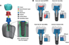
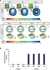
Fig. 1 shows FE models and the structure of the implant complex of three cases that used CLF implant prostheses and one case that used a cement-retained (CR) implant. For each implant system, the model consisted of the crown, resin/cement layer, abutment, screw, and the implant inserted in the bone (Fig. 1A). Three CLF implant prosthesis test groups were classified according to the shape of the abutment: the resin-air hole-full (RAF) group had abutments with air hole filled with composite resin, the resin-air hole (RA) group had abutments with air holes without resin fillings, and the resin-no-air hole (RNA) group had abutments with no air holes. For CLF implant systems, the air groups (RA, RAF) and no air group (RNA) depended on the abutment geometries. The sunken structure on the occlusal surface of the abutment was designed to reveal the effect of stress distribution on the implant and abutment. CR implant prosthesis was used as the control group. Each implant system used an internal hex implant with a diameter of 4.0 mm, implant length of 10 mm, and a total length of 20 mm. The design of the implant models was provided by the manufacturer (Osstem Implant Co. Ltd., Seoul, South Korea).
The modeled bone section consisted of a cancellous bone fragment surrounded by a 2-mm layer of cortical bone and a cylindrical part surrounding the implant. The FE models with dental components were modeled using Hounsfield units.17 Using 3D modeling software (3-matic Research 9.0, Materialise Corp., Leuven, Belgium), the bone structure of the posterior section of the mandible and implant components were modeled by proper scaling, aligning, and surface simplification. The cylindrical parts near the bone-implant interface were additionally set to investigate the surrounding area of the implant. The thickness of the resin layer was set to 30 µm for the CLF implant system, 200 µm at the top, and 30 µm everywhere else for the CR system (Fig. 1B).
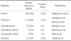
All geometries were converted into the FE model after generating the surface and volume mesh and exported to the FE analysis software (ABAQUS 6.14, Dassault Systems SIMULIA Corp., Providence, RI, USA) using the four-node tetrahedral elements and six-node triangular prism elements. The total number of elements used for each model ranged from 3,038,810 to 3,508,862. The components of the implant system and the surrounding bone were assumed to be homogeneous, isotropic, and linearly elastic materials. The mechanical properties are presented in Table 1.1819202122
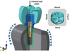
To reproduce the preload from screw tightening and the masticatory forces, the FE analysis was performed as a general static analysis in two steps: a preloading step and a mastication step. The preload was applied on the screw to approximate the relationship between an abutment and an implant fixed by screws. The preload was calculated to apply a torque of 32 Ncm using a formula provided by a previous study (Fig. 2).23 After the preloading step, a total force of 200 N was applied to each of the 60 nodes on 3 cusps and 3 fossae in the vertical direction (Fig. 2). During the two steps, both ends of the bone block were fixed in all directions at the mesial and distal surfaces of the bone.
For the interaction conditions, the abutment and implant were tightly connected by screw tightening (Fig. 3). The interaction conditions used in the analysis included two sets of contacts: Contact 1 of the CLF implant was the contact surface between the resin layer and the abutment with a friction coefficient of 0.25 and Contact 1 of the CR implant was a fully bonded cement layer-abutment interface. Contact 2 was the contact surface between the abutment and implant with a friction coefficient of 0.16.242526 Contact analysis ensured the transfer of load and deformation between the titanium-titanium interfaces and the resin-titanium interfaces.27 To simulate perfect osseointegration, all interactions incorporating the implants and bone were simulated as tie conditions. The tie condition was also used for crown-resin/cement interfaces.
To analyze the stability of the CLF implant system compared with the CR implant system, we evaluated the implant components and bones by applying valid evaluation criteria. The von Mises stress and principal stress were used to evaluate the stress values and distributions of the implant components. To predict the risk of microleakage and infection, the contact open (COPEN) values were calculated to analyze the gap formation at the contact surfaces.
For bone tissue analysis, the micro-strain levels in the bone surrounding the implants were evaluated by the bone remodeling thresholds, as suggested by the Frost mechanostat hypothesis.28
The statistical analysis was performed to evaluate the effect of the different abutment geometries and the type of abutment-crown connection after testing the normality of each data using the Shapiro-Wilk test and equal variance.293031 The implant component and the bone cylindrical part were assessed using Kruskal-Wallis H test of variance on ranks.32 All the tests were performed using 50 maximum values of each component.32 Values of P < .05 were considered to be statistically significant for each implant system in the non-parametric analysis. For multiple comparisons, the Mann-Whitney test and Bonferroni correction were adopted as post hoc testing to indicate the differences among the groups, using a 5% significance level for multiple comparisons.32 The values of P < .008 were considered to be statistically significant using Bonferroni correction because the 6 tests were performed for each comparison. All statistical analyses were performed using statistical software (SPSS version 20.0, IBM Corp., Armonk, NY, USA).
RESULTS
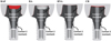
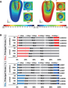
Figure 4 illustrates the stress distribution on Contact 1 and Contact 2, and the results for evaluating the influence of the implant systems are summarized in Table 2 and Table 3. The stress mainly occurred in the buccal direction and the CLF implant system induced much higher or similar stresses in the abutment at Contact 1. The values reflecting the maximum stress of the abutment were as follows: RAF, 25.6 MPa; RA, 23.4 MPa; RNA, 20.0 MPa; CR, 15.8 MPa.
In contrast to the result for Contact 1, the maximum stresses for the CLF implant system at Contact 2 were lower or similar to those of the CR implant system, except for RNA (Fig. 4). Comparing CR with CLF in terms of the abutment surfaces, the use of abutments with no air shape induced 9% – 13% higher stress than CR (P < .001), while the use of abutments with an air shape induced 10.4% – 15% lower stress than CR (P < .001). Evaluation of the von-Mises stress among the abutment and implant according to the abutment geometry showed that the no air group of RNA induced 9.3% – 14% higher stress than the air group (P < .001).
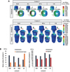
We considered the contact open (COPEN) values to analyze the microleakage and infection as shown in Fig. 5, and Table 2 and Table 3 show the detailed results of the statistical analysis. The COPEN values in Contact 1 (abutment-resin interface) were measured from 0.88 to 1.19 µm, and the values in Contact 2 (abutment-implant interface) were 24.4 to 24.7 µm.
For the bone stability analysis, the micro-strains were evaluated as shown in Fig. 6. It shows the maximum and minimum principal strain distributions representing the tensile and compressive strains in the peri-implant bone induced by the CLF implant system and CR implant system. The strain distribution was similar in all cases, as shown in Fig. 6A. The percentage of bone volume is shown according to the strain levels in Fig. 6B. The volume over the fatigue failure range was up to 0.0007% of the cancellous bone surrounding the implant. The results for the CLF and CR implant systems showed a similar percentage of bone volumes over the range of fatigue failure strain levels.
DISCUSSION
The biomechanical properties of the CLF crowns were evaluated in this study. Comprehensive FE analysis was conducted on the impact of stress on the implants and abutments and its effect on the surrounding bone.
For maximum principal stress distribution of the resin layer in Fig. 4B, the cement layer used for CR was associated with a higher risk of fracture than the resin layer, since the stress induced in association with CR (29.4 MPa) was higher than that associated with the CLF implant system (4.7 to 10.0 MPa). The stress value of the cement layer of the CR type was high because of the tied interaction condition among the abutment-cement-crown. As a result, the external force applied to the crown was more uniformly transmitted through the cement layer to the abutment. The 3D position between the crown and the abutment was relatively deformed by external force; for example, there was gap formation of up to 1.2 µm in the marginal area for the RA group as shown in Fig. 5. This indicates that the high stress in the cement layer was influenced by the fully bonded cement between the crown and the abutment.
The contact analysis of gap formation at the implantabutment interface was previously performed by FEA.33 There was 13 µm of gap under 100 N of vertical loading, which is comparable to 25 µm of gap under 200 N of vertical loading in this study. Regarding the gap formation in the marginal area of Contact 1, a small gap of less than 0.1 µm represents the stability between the crown and abutment even if there is no cementation in the CLF crown. All groups showed around 25 µm of gap formation in Contact 2, which indicates that the stability of the CLF implant crowns was comparable to that of the CR implant crowns, regardless of the presence or absence of an air hole.
Strain occurred primarily in the implant thread in the buccal direction, and strains of over 1000 µε were observed in the bone tissues around the implant apices. As shown in Fig. 6B, the bone volume showed overstrain (hypertrophy and fatigue failure) and ranged around 0.0012 % to 0.0013% in the cortical bone and 0.006 % to 0.007 % in the cancellous bone. Over 99% of the bone volume was ranged under 2500 µε within the physiologic range. Comparison of the volume fractions according to the strain levels of bone remodeling showed that different abutment geometries or interaction conditions for the resin layer did not significantly affect the bone strain. Consequently, the strain values of the surrounding bone associated with the CLF crown were similar to those of the conventional CR implant crown. For minimum principal strain in the cancellous bone (Table 2), there was no statistically significant difference according to the abutment geometry or connection type of the crown and resin layer (P > .008).
According to the Frost mechanostat hypothesis, a high strain level (2500 to 4000 µε) stimulates remodeling activity, increases the bone density, and generates a strain level greater than 4000 µε, which induces the generation of internal cracks that result in bone failure.28 In a recent study, the bone strain around the implant was found to be 4500 µε under 100 N of vertical loading, which is similar with 10,000 µε of strain under 200 N of vertical loading in this study.34 Verification of the mechanostat theory in mandible remodeling after tooth extraction was performed through FEA and animal studies. It showed that the mechanostat theory could predict mandible remodeling after tooth extraction.35 However, there are few studies examining the proportion of strain volume. Over 4000 µε on the bone surrounding the implant was below 0.001%, and overstrain could occur within a short period at the moment of mastication. Thus, it was assumed that the surrounding bone can be physiologically adaptive under high-strain conditions because of its small volume and the short period of mastication.
Each component, including the cement layer, consisted of numerous small elements, which assure the quality and results of the FE analysis in this study. However, this study had several limitations. Varying the direction of loading conditions would have resulted in a more realistic simulation. Additional fatigue testing under cyclic loading and non-linear conditions would also have been helpful. Finally, future studies with mechanical testing using the specimens are required.
CONCLUSION
The air group of the CLF implants was similar or better in terms of stability than the conventional cementation implant system. The filling of the air hole with resin in the CLF implant air group did not cause a significant difference in the stability. Also, the air hole status and the type of relining resin did not significantly affect the stability of the cancellous bone. Thus, there were no disadvantages in terms of biomechanical features when using the CLF system compared to the conventional CR system.


 XML Download