

 PDF
PDF ePub
ePub Citation
 Print
Print


INTRODUCTION
The internal connection type implants have been reported to have more reliable connection stability than the external connection type implants. In external connection type, only the screw secures the abutment to the implant when mechanical load is applied. On the other hand, friction and locking of the tapered interface between the abutment and the implant mainly provide stable retention in internal tapered connection type.1 In two-piece dental implant systems, a microgap is avoidable at the implant-abutment interface and the dimension of this microgap could be influenced by external load applied on the abutment.2 A microgap was significantly decreased in a Morse taper implant connection after mechanical cyclic loading, which was caused by settling of the abutment and deformation of the interface.34 Seol et al.5 showed that the total length of the implant-abutment assembly was significantly decreased in internal tapered implant and no significant axial displacement occurred in external connection type implant. The amount of axial displacement in internal connection type implant can be affected by a variety of factors including interface design, the abutment materials, and surface condition associated to the coefficient of friction.67 As axial displacement occurs, the preload between the screw and the abutment is reduced and the risk of screw loosening increases. If the interface between the abutment and the implant becomes too small, it is anticipated that the connection stability increases by the increased frictional force.89
The computer-aided design/computer aided manufacturing (CAD/CAM) system, which has been used in various restorative treatments ranging from a simple prosthesis to extensive implant prostheses, offers the advantage of ensuring constant results and productivity.10 In particular, the use of CAD/CAM customized abutments can reproduce the anatomically ideal abutment shape and produce prostheses with a more aesthetic and natural emergence profile at the gingival region.11 In recent years, many companies have produced CAD/CAM customized abutments, but the accuracy and the stability of CAD/CAM abutments are not well-documented. Also, there is still lack of long-term clinical research and experimental study.
The purpose of this study was to evaluate the mechanical stability of the CAD/CAM customized abutments compared to prefabricated abutment in Morse taper internal connection type implant system. In this study, the same form of CAD/CAM customized abutments and prefabricated abutment were connected to the same kinds of implants. The amount of axial displacement and the removal torque values (RTVs) were measured before and after cyclic loading, and the tensile removal force to dislodge the abutments was measured after cyclic loading.
The null hypothesis was that no significant difference would be found in the axial displacement, the removal torque reduction, and the tensile removal force between the prefabricated abutments and the CAD/CAM abutments.
MATERIALS AND METHODS
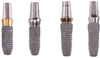
The study was conducted using implant-abutment assemblies manufactured by two different manufacturers (Group Os: Osstem TS II R4.0 × 10 mm, Osstem Implant, Seoul, Korea; Group De: Implantium 4.0 × 10 mm, Dentium Implant, Seoul, Korea). Fourteen implant-abutment assemblies were prepared for each manufacturer group. They were divided into two groups (n = 7) of prefabricated abutments (Os-P, De-P) and CAD/CAM customized abutments (Os-C, De-C), which were connected to the same kinds of implants. All the assemblies included conical-hex internal connection with 11° Morse taper. CAD/CAM abutments were designed to the same form of the prefabricated abutment (Os-C: D 4.5 mm, G/H 2.0 mm, H 7.0 mm, Taper angle 6°; De-C: D 4.5 mm, G/H 2.5 mm, H 5.5 mm, Taper angle 6°) and fabricated by CNC milling of premilled cylinder grade 5 titanium alloy (Ti-6Al-4V) with ARUM 5X-200 (Arum Europe GmbH, Frankfurt, Germany) : number of axis 5; accuracy 5 µm; spindle power DC 3.0 KW; spindle speed 2,000 – 60,000 rpm; ATC (automatic tool changer) number of tools 15. The prefabricated abutments used in group Os-P were also made of grade 5 titanium alloy, and they were pure grade 4 titanium (CP-Ti grade 4) in group De-P. The same kinds of screws were used in prefabricated abutments and CAD/CAM abutments (Table 1, Fig. 1).
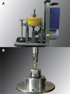
The custom-made cyclic loading device simulating vertical loads of human mastication was manufactured for this experiment (Hatis, Hwasung, Korea) (Fig. 2(A)).512 Implants were clamped into the holder (Nikken, Tokyo, Japan) with a torque wrench (230DB3, Tohnichi Co., Tokyo, Japan) at a torque of 300 Ncm. A hemispherical metal cap, which has been designed to mimic the presence of crown and prevent deformation of the abutment from the external load, was applied onto the abutment (Fig. 2(B)). Tightening torques of 30 Ncm were applied to the abutment screw according to the manufacturers' recommendation, twice at 10 minutes intervals with a digital torque gauge (MGT50, Mark-10 Corp., Copiague, NY, USA). Loads of 150 N, which was considered as the physiological occlusal force on the single posterior tooth,131415 were applied at a frequency of 3 Hz for 106 cycles, simulating 1 year of function.516 Calibration was performed before each measurement using a load cell (MNC-500L, CAS Korea, Seongnam, Korea) and a strain analysis program (STT-200P, CAS Korea, Seongnam, Korea).
The total length of implant-abutment assembly was measured with an electronic digital micrometer (No. 293-240, Mitutoyo) with accuracy up to 1 µm. As a reference point, the length of the implant-abutment assembly after tightening the abutment screw with 5 Ncm was measured.12 The length of each assembly was measured after initial with 30 Ncm. Applying the vertical cyclic load, the length of the assembly was measured after 10, 102, 103, 104, 105, 5 × 10⁵ and 106 cycles and the change between the cycles were calculated (Fig. 3).5
After initial tightening with 30 Ncm twice at 10 minutes intervals, a digital torque gauge was used to measure the removal torque values.51217 Then, after 106 cyclic loading, the removal torque was measured again in the same way. The reduction rate% was also calculated to compare among the groups: RTV reduction rate% = ((30 − RTV) / 30) × 100.12
After 106 cyclic loading, the abutment screw was removed to measure the removal torque value, and the tensile force required to dislodge the abutments from the implants was measured in a universal testing machine (Instron). Each abutment had a 1.2 mm diameter hole 3.5 mm below the top, through which a metal wire was passed to pull it. The implant was fixed at the bottom part of the machine, and then tensile force was applied at a speed of 0.5 mm/min until the abutment was dislodged.18
A repeated measures analysis of variance (ANOVA) and a pattern analysis based on the regression model with logarithmic transformation were performed to evaluate the effect of cyclic loading on the axial displacement of the abutment. The Wilcoxon signed-rank test was conducted to compare before and after RTVs within each group. The Mann-Whitney U test was used to compare the RTV reduction rates before and after cyclic loading and the tensile removal force after cyclic loading between the groups. Pearson correlation analysis was performed to analyze the relationship between the axial displacement value, the RTV reduction rate and the tensile removal torque. Statistical analyses were performed with SPSS statistical software (IBM SPSS ver. 22.0, IBM Corp, Armonk, NY, USA). The P value of less than 0.05 was considered statistically significant.
RESULTS
The length assembly at 5 Ncm tightening was determined as the baseline,16 and the axial displacement of the abutment after initial tightening with 30 Ncm was measured. The axial displacement value after initial tightening was significantly greater in CAD/CAM abutments (Os-C) in group Os, but it was greater in prefabricated abutments (De-P) in group De (P < .05). After 106 cyclic loading, there was no significant difference between prefabricated abutments and CAD/CAM abutments in both group Os and group De (Table 2).
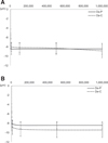
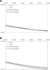
The axial displacements after various cyclic loadings are shown in Table 2 and Fig. 4. After cyclic loading, the axial displacement values were significantly increased up to 104 cycles (P < .05), but after that, no significant increase was observed. No significant difference was found between the prefabricated abutments and the CAD/CAM abutments at any number of cycles (P > .05). After 106 cyclic loading, no significant difference was found between the prefabricated abutments and the CAD/CAM abutments (P > .05).
To analyze the estimated effect, the regression model was constructed with logarithmic transformation of both the axial displacement values and the number of cycles (Table 3, Fig. 5). In all groups, the linearity on logarithmic transformation was observed (P < .05).
The RTVs and the RTV reduction rate% before and after cyclic loading are presented in Table 4. The RTVs after 106 cyclic loading were significantly lower than those before cyclic loading in all groups (P < .05). There was no significant difference in RTV reduction rate% between the prefabricated abutments and the CAD/CAM abutments before cyclic loading. However, after 106 cyclic loading, it was greater in the CAD/CAM abutments than the prefabricated abutments in both manufacturer groups (P < .05).
After 106 cyclic loading, the abutment screws were removed measuring RTVs. Even after that, all the abutments were sustained in implants and only after tensile force was applied, they were removed from the implants. Mann-Whitney U test revealed no significant difference between the prefabricated abutments and the CAD/CAM abutments in both manufacturer groups (Table 4).
Pearson correlation analysis was performed for demonstrating the relationship between the axial displacement, the removal torque reduction, and the tensile removal force after cyclic loading (Table 5). In Os group, the significant relationship between these three values was observed, whereas no significant relationship was found between any values in De group.
DISCUSSION
The null hypothesis was rejected because a significant difference was found in the RTV reduction rate% between prefabricated abutments and CAD/CAM abutments (P < .05), even though no significant differences were found in the axial displacement and the tensile removal force (P > .05).
The axial displacement occurred in all groups with initial tightening of the abutment screws. This could be explained by the phenomenon known as ‘settling effect’.19 This phenomenon is based on the inherent geometric character of the conical connection structure. When the cone-shaped abutment is placed into the implant lightly, at the first moment, not all areas of the interface between the abutment and the implant are in contact. This uneven contact is inevitable due to the manufacturing tolerance. After the axial force is transmitted by the abutment screw tightening with manufacturers' recommended torque, the axial displacement of the abutment into the implant occurs.202122 The axial displacement after initial tightening was greater in Os-C than Oc-P; however, it was greater in De-P than De-C (P < .05) (Table 2). From the results of the group Os, which used prefabricated abutments and CAD/CAM abutments, both grade 5 Ti alloy, it could be speculated that more uneven contact occurred at the interface between the abutment and the implant in CAD/CAM abutments than in prefabricated abutments, thus more axial displacement occurred in CAD/CAM abutments after initial tightening. Since the prefabricated abutments used in group De-P were made of CP-Ti grade 4 and the CAD/CAM abutments used in group De-C were grade 5 Ti alloy, the difference in axial displacement between group De-P and De-C could be due to different abutment materials that could affect the deformation of the surface. Jo et al.23 showed that the settlement of the CP-Ti grade 4 abutments after mechanical loading was greater than that of grade 5 Ti alloy abutments. Additional studies with CAD/CAM abutments made of different materials are needed.
After cyclic loading, the axial displacement occurred in all groups and no significant difference was found between prefabricated abutments and CAD/CAM abutments. The axial displacement values were significantly increased up to 104 cycles (P < .05). After that, no significant increase was observed. The axial displacement values after 106 cycles of CAD/CAM abutments were not significantly different from prefabricated abutments (Os-P = 8.4 ± 2.4 µm, Os-C = 8.9 ± 2.9 µm, De-P = 8.4 ± 1.5 µm, De-C = 9.4 ± 3.2 µm). The linearity on logarithmic transformation was observed in all groups, and this result suggests that the axial displacement occurs continuously even after 106 cyclic loading. Further studies with an increased number of cycles greater than 106 to reflect the longer clinical use are required.
The RTVs were decreased in all groups after initial tightening when no mechanical load was applied.182024 It could be explained by ‘settling effect’ mentioned above, which can cause the decrease of preload. This is why it is recommended to retighten the retention screw 10 minutes after the initial tightening.82425 According to the previous study by Breeding et al.,24 the deformation of the interface of components may cause a loss of preload by 2% to 10%. The torque reduction obtained in the present study was beyond this range (Os-P = 24.57 ± 0.61%, Os-C = 23.71 ± 1.29%, De-P = 23.50 ± 0.58%, De-C = 23.57 ± 1.79%), similar to the results of Assunção et al.22 There was no significant difference between prefabricated abutments and CAD/CAM abutments. After 106 cyclic loading, however, the RTV reductions were greater in CAD/CAM abutments than in prefabricated abutments (Os-P = 44.29 ± 2.70%, Os-C = 52.14 ± 5.50%, De-P = 40.71 ± 2.12%, De-C = 55.71 ± 8.60%). Preload loss may be influenced by physical properties of the screws, such as materials, design, composition, dimensions, and friction between surfaces.26272829 Since the same type of screws were used in prefabricated abutments and CAD/CAM abutments, the differences of RTV reduction rate due to the abutment properties can be suggested. Preload loss after cyclic loading might be caused by the axial displacement of the abutment, which allows the tension at the screw thread interface to be reduced.20 After settling effect by initial tightening, microroughness of the interface and friction may still be present. When external load is applied, the tension of the screw head to the abutment base and the thread interface was reduced and removal torque loss occurred.262730 Therefore, it is recommended to retighten the abutment screw several days after applying external load to the prosthesis. The results of this study indicate that CAD/CAM abutments are more prone to preload loss than prefabricated abutments. It may be caused by the greater tendency of micromotion of the abutments and microgap between the screw head and the abutment base due to the manufacturing method. Further studies with misfit and microgap of interfaces of CAD/CAM abutments relating to the fabrication methods are needed.
In all groups, even after the abutment screws were removed after cyclic loading, all the abutments remained in implants, and only after the tensile force was applied, the abutments dislodged from the implants. This suggested that the friction increased due to increased surface contact between the interfaces by the axial load.31 In the Morse taper system, lateral loading is resisted mainly by the taper interface, known as positive or geometric locking, which is responsible for protecting the abutment threads from excessive functional load.1 The results of this study suggest that the micromovement of the abutment generated in abutment-implant interface contribute to the connection stability. That is, the friction at the abutment-implant interface is a major determinant of the connection stability, and the abutment screw acts as a supportive role to the abutment retention in Morse taper system. Clinically, this frictional force caused by the micromotion of the abutments after cyclic loading makes it difficult to remove the abutment from the implant when it is necessary.18 Tensile forces measured in this study were not significantly different among the groups (Os-P = 47.03 ± 3.47 N, Os-C = 47.39 ± 7.66 N, De-P = 49.71 ± 5.47 N, De-C = 50.53 ± 6.81 N). This result suggests that the connection stability due to the friction at the interface of CAD/CAM abutments may not be different from prefabricated abutments and the abutments may be dislodged from the implants when approximately 50 N is applied.
Theoretically, as the amount of axial displacement increases, the contact of interface becomes more intimate resulting in increasing tensile removal force and decreasing removal torque due to the loss of tension of the screw-abutment and the thread interfaces. However, the significant correlation among the axial displacement, the removal torque reduction, and the tensile removal force was observed only in Os group, and there was no significant correlation in De group. Therefore, additional studies are needed to investigate the effect of fabricating methods.
Considering the limitations of in vitro studies, the experimental conditions were limited to hex-indexed abutments of single implant-supported prosthesis placed in a posterior region. It must be considered that the present study has limitations to simulate complex biomechanical properties in clinical condition. Thus, further in vitro and in vivo studies are necessary to evaluate the behavior of CAD/CAM abutments including the effect of the internal hexagonal index and the effect of the applying force of cyclic loading.
CONCLUSION
Within the limitations of this in vitro study, the following conclusions can be drawn. All groups presented significant decreases of removal torque before and after cyclic loading compared to the initial torque. CAD/CAM abutments presented a significantly greater removal torque reduction% than prefabricated abutments after 106 cyclic loading. However, the use of CAD/CAM abutment did not significantly affect the amount of axial displacement and tensile removal force after cyclic loading. The friction at the abutment-implant interface is a major determinant of the connection stability in Morse taper system, and this connection stability due to the friction at the interface of CAD/CAM abutments may not be different from prefabricated abutments.


 XML Download