

 PDF
PDF ePub
ePub Citation
 Print
Print


INTRODUCTION
Recently, 3D printers have been applied in various medical fields. Creating individualized implants for patients has become the most popular application in the surgical field, and the production of phantom models is also becoming more common.12 Making surgical instruments could be a good field of application for 3D printers, although attempts to do so have proven limited. When surgeons have new ideas on surgical instruments, they usually make prototypes using metal, and test their feasibility in cadavers. These processes can be tedious, costly, and time-consuming.3
In the past, endoscopic spine surgery has primarily been applied for lumbar discectomy. However, with further development of endoscopic equipment and techniques, the indications thereof have been expanded to spinal stenosis.4 Since the view and instrument are fixed, conventional endoscopic spine surgery has limitations in decompressing foraminal stenosis sufficiently, without excessive facet joint resection.5 To overcome the limitations of endoscopic spine surgery, bi-portal endoscopic spine surgery was recently developed. Due to an independently working portal and the widespread availability of conventional instruments, bi-portal endoscopic spine surgery has become a breakthrough technique in endoscopic spine surgery.6 Although bi-portal endoscopic spine surgery has numerous advantages, conventional endoscopic surgery is still useful. Surgeons, however, cannot apply both endoscopic surgery techniques at the same time, due to the completely different designs of the surgical instruments used in each technique. In this study, we aimed to design a new endoscope-assisted spine surgery system that could permit the performance of both conventional and bi-portal endoscopic spine surgery using a single surgical instrument. We also sought to demonstrate the usefulness of 3D printing for the development of complex surgical instruments.
MATERIALS AND METHODS
Workflow of surgical instrument development
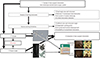
For the development of the new surgical instrument, four steps were needed (Fig. 1). The first step was the conceptualization of the new surgical instrument, and the second step involved making a prototype based on new concept and ideas. The third step was to make a patient-specific spine model, and the fourth step was the evaluation of the new surgical instruments. 3D printing technique was primarily applied in two parts: making the prototype instrument and the patient-specific model to test the new instrument.
Endoscope-assisted spine surgery instrument concept and design
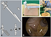
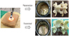
Two cannulas were joined together: one for an endoscope, and another for surgical instruments. The combined cannula had snowman-shaped opening, with major and minor axis diameters of 10.34 mm and 9.16 mm, respectively. The instrument cannula could be blocked with a rubber cap for conversion to bi-portal endoscopic surgery (Fig. 2A), and two cannulas were jointed to reduce diameter and to adjust the endoscopic view (Fig. 2B and C). The new system separated the instrument cannula from the endoscope, which allowed the use of thicker instruments (Fig. 2C and D). The instrument cannula was designed to have a 10-mm diameter; therefore, it was possible to use both an endoscope and classical instruments (Fig. 2A). After a 10-mm skin incision, the new endoscope-assisted spine surgery system was inserted (Fig. 2B).
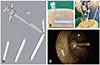
If an extra portal was needed, we made a 5-mm incision independently and inserted a new working portal using the desired angle (Fig. 3A and B). To position the extra working portal in the optimal place, a magnetic connector was designed. The angle between the primary cannula and extra portal was designed to be 18 degrees. The extra portal could move together with the endoscope, and the shape of the extra portal could be selected as circular or semicircular (Fig. 3A). After a 5-mm skin incision, the extra working portal was inserted and linked to the magnetic connector of the new endoscope-assisted spine surgery system (Fig. 3B, C, and D). We used standard 4-mm diameter and 0-degree endoscopes for the bi-portal endoscope system.
Customized patient-specific 3D spine model
We made a customized patient-specific spine model. The process for making the spine model consisted of five steps: 1) 3D modeling of spine components using MR and CT scans, 2) making 3D-printed spine components via 3D printer, 3) making silicone molds using 3D-printed spine components, 4) making spine components in consideration of physical properties, and 5) assembly of the patient-specific model.
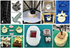
MR images and CT scans of patients were obtained using a picture archiving and communication system (PACS; INFINITT, Seoul, Korea). Imaging data were imported to 3D Slicer software v 10.0 (https://www.slicer.org), free, open source software for medical imaging computing and 3D reconstruction, according to the Digital Imaging and Communications in Medicine format (Fig. 4A). After the 3D digital images were calculated and reconstructed, every component was separated and exported to a 3D printer (Creatable D3, A-Team Ventures, Seoul, Korea) (Fig. 4B). After the 3D-printed spine components were obtained, silicon molds were made (Fig. 4C). Then, we decomposed the spine structures and assigned these components into two groups. The first group comprised structures that needed to have their shape and rigidity preserved, such as bone, and the other group comprised structures that had similar elasticity to human tissue, such as discs, nerves, and ligaments. We used various silicones and polymers, based on manufacturer specifications and reported papers (Fig. 4D).7 Using each silicone mold, vertebral bodies were cast with urethane foam (FOAM-iT5 and FOAM-iT10, Smooth-On, Macungie, PA, USA), intervertebral discs, paraspinal muscles with polyurethane rubber (VytaFlex 10, Smooth-On), neural structures, and ligament flavum with silicone (Dragon skin 10, Smooth-On) (Fig. 4D). Supportive structures were cast with polyurethane rubber (PMC-770, Smooth-On), body frames were cast with urethane foam (FOAM-iT5), and skin with muscle components was cast with polyurethane rubber (VytaFlex 10) (Fig. 4E). After making all spine components, every part was assembled (Fig. 4E). We made two pairs of patient-specific spine models for lumbar 4–5 paramedian disc herniation and lumbar 4–5 foraminal disc herniation on the left.
Comparison according to surgical instrumentation and approach
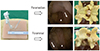
The surgical results were compared according to surgical instrumentation and methods. Surgical methods were paramedian discectomy and foraminal discectomy (Wiltse posterolateral spinal approach).8 Surgical results of the new endoscope-assisted spine surgery system were compared with a tubular retractor (16-mm diameter, Medtronic Sofamor Danek, Memphis, TN, USA) using a standard surgical technique (Figs. 5 and 6). Until sufficient nerve decompression was obtained, a tubular retractor and the new system were used to perform discectomy using two different approaches (paramedian, foraminal discectomy), and the degrees of bone resection were compared after surgery.
RESULTS
Using a conventional tubular retractor and the new system, discectomies were performed through paramedian and foraminal approaches using two pairs of customized patient-specific 3D spinal models (Supplementary Videos 1, 2, 3, 4, only online). The paramedian approach using the tubular retractor was performed using a conventional method (Fig. 5, Supplementary Video 1, only online).9 The paramedian approach using the new endoscope-assisted spine surgery system at the lumbar 4–5 and the left paramedian disc herniation was also performed (Fig. 6, Supplementary Video 3, only online). After making a 10-mm incision in the skin layer near the midline, we inserted the new system (Figs. 2C and 6), and a 4-mm endoscope was positioned into the endoscope cannula. After saline inflow was implemented, discectomy was performed using conventional full endoscope instruments (Fig. 2C and D). This should have provided us with enough vision for sufficient decompression, and the view and resolution were very similar to conventional endoscopic spine surgery (Fig. 2D). An additional 5-mm incision was made (Fig. 3B), and the extra portal with magnetic connector was positioned properly (Fig. 3B and C). Circular and semi-circular shapes of extra portals were available, and discectomy was possible using various conventional surgical instruments (Fig. 3D, Supplementary Video 3, only online). Since the surgical instruments had gone down the working portal wall, the instrument could be placed safely.
The foraminal approach using the tubular retractor was performed according to a conventional method (Fig. 5, Supplementary Video 2, only online). Foraminal discectomy was performed with the new endoscope-assisted spine surgery system using the lumbar 4–5, left foraminal disc herniation model. After partial resection of the superior articular process, exiting nerve roots and foraminal discs were identified, and disc materials were removed with pituitary forceps via the extra portal (Fig. 6, Supplementary Video 4, only online). The authors compared the bone destruction of these spine models after discectomy (Figs. 5 and 6). Comparison of the conventional tubular retractor and the new endoscope-assisted spine system showed that sufficient neural decompression and discectomy were achieved by both surgical approaches. However, damage to the superior articular process was significantly reduced with the foraminal approach using the new surgical system (Figs. 5 and 6, foraminal approach).
DISCUSSION
Herein, we described our process of developing a complex surgical system using a 3D printer, and confirmed the usefulness of the 3D printer for the development of surgical instruments. Endoscopic spine has rapidly evolved since it was initially described by Ruetten, et al.10 With various reports of decompressive surgery for spinal stenosis, endoscopic spine surgeries have been frequently used for spine treatment.4 The goal of minimally invasive surgery is to achieve the same results as those of conventional surgery, while minimizing damage to the normal structure.11 Bi-portal endoscopic surgery offers a greater range of motion of instruments and availability of conventional surgical instruments, and it can be applied to various pathologies, including stenosis.12 In this study, we designed a new endoscope-assisted spine surgery system that could allow for both conventional and bi-portal endoscopic spine surgery methods to be applied at the same time, and our trial surgery showed that the new system works properly. The expected advantages in the new endoscopic spine surgery over tubular retractor, conventional one-portal, and bi-portal endoscopic surgeries are summarized in Table 1. In this study, we only performed comparative surgery using a tubular retractor. Sufficient neural decompression and discectomy were achieved with both the tubular retractor and the new endoscopic spine surgery systems, although damage to the superior articular process was significantly reduced with a foraminal approach using the new endoscopic spine surgery system.
Rankin, et al.13 reported that the estimated cost per unit of a 3D-printed instrument is roughly 1/10 of the cost of stainless steel instruments. Testing a prototype with a cadaver is also very different from the actual operative situation, and the process is also very expensive. Recently, it has become possible to make patient-specific models with high accuracy, and personalized 3D printing prostheses can be extensively applied in clinical practice. High accuracy is essential for 3D printers, and previous studies have validated the accuracy of 3D-printed spine models. Wu, et al.14 compared CT images of cervical, thoracic, and lumbar vertebrae against 3D-printed models, and found that the 3D-printed models had strong anatomical correlations. Previous studies have assessed the accuracy of 3D-printed models representing cadaveric pelvises, and observed no significant differences between them.15 Kidney models using silicone materials have been found to show similar elasticity with real kidneys, as well as biocompatible properties on MR and ultrasound imaging.16 Such disease models can be made repeatedly, and comparative testing can be possible using the same models.
3D printers have been used in spine surgeries earlier than in other surgeries. A 3D titanium alloy vertebrae was implanted for cervical spine reconstruction following a Ewing sarcoma resection, and a 3D-printed implant for pelvic reconstruction following hemi-sacral resection was successfully applied.1718 Multiple studies have reported the successful use of patient-specific 3D-printed implants in complex spinal pathologies.19 Although accurate fabrication of patient-specific implants has been described in many studies, literature on 3D printer utilization for surgical instrument development is scarce. Until now, making only simple surgical instruments, such as retractors, forceps, and hemostats, has been attempted with the use of 3D printing.1320 In this study, we wanted to show the usefulness of 3D printers for the development of complex surgical instruments, and overall, we deemed that 3D printers can be effectively applied in the development of complex surgery instruments. We are confident that many surgeons would be able to test their ideas easily with 3D printing.
Our new endoscope-assisted spine surgery system and trial with a 3D-printed patient-specific model involved many limitations. Postoperative outcome analysis using a 3D-printed model could be different from using actual patients. Also, the surgical trial was conducted only once, and it was not compared to conventional endoscopic spine surgery. Since we could not confirm whether the magnetic connector would be adequately bonded when it is inside a real human, a cadaver trial is needed to confirm this matter. However, the purpose of this study was to show the usefulness of 3D printers for the development of complex surgical instruments. The authors are well-aware that the new endoscope-assisted spine surgery system needs further improvements, and future studies with more complicated degenerative spinal diseases and deformed patient-specific models are required. Nevertheless, we were able to make and test a new idea on surgical instruments quickly, in addition to introducing the possibility of a new endoscope-assisted spine surgery system using 3D printing technology.


 XML Download