

 PDF
PDF ePub
ePub Citation
 Print
Print


INTRODUCTION
Among the two typical methods for extraction space closure, (i.e., sliding mechanics and loop mechanics), sliding mechanics is often used owing to the simplicity of wire bending, easy reactivation, and patient comfort.12345 Nevertheless, various mechanical properties, such as archwire stiffness, friction, and bracket-wire play, have been suggested as determinants of the resultant tooth movement.678 In conventional sliding mechanics, manipulation of the main archwire, e.g., by using a gable bend or reverse Curve of Spee, has been proposed to reduce undesirable movement of the posterior segment.8910 Therefore, the use of interradicular orthodontic miniscrews has gained popularity, because it is effective for stabilization of anchorage segments.12345 However, previous studies have reported undesirable posterior segment displacement, despite the use of miniscrews, depicting rotation of the whole arch relative to the center of resistance (CR) and the force vector.25711 Therefore, it is crucial to clarify the displacement patterns in the posterior segment in sliding mechanics using miniscrews.
In sliding mechanics, the anterior segment is connected to the posterior segment via a continuous archwire. The whole arch may be considered a single unit; however, the respective anterior and posterior segments exhibit differential movement patterns depending on the mechanical properties of an archwire (i.e., rigidity and friction etc.).56101112 An identical single force may lead to different displacement patterns depending on the stiffness of the archwire and/or the presence of friction. However, few studies have examined the response of each segment to the varying archwire stiffness and friction conditions of a continuous archwire.
Finite element methods (FEMs) have been widely used to quantify and visualize the displacement pattern of three-dimensional objects. In terms of friction, nonlinear FEM analysis is a reasonable approach for simulation and prediction of tooth displacement under friction, given that these analyses cannot be performed using a linear analysis approach.13
The purpose of the present study was to investigate the effect of archwire stiffness and friction changes on displacement patterns in the maxillary posterior segment during anterior segment retraction in sliding mechanics using orthodontic miniscrews.
MATERIALS AND METHODS
Construction of the finite element model
Three-dimensional finite element models of the maxillary dentition with extracted first premolars, periodontal ligaments (PDLs), and alveolar bone were constructed via three-dimensional laser scanning of a dental model(Model-i21D-400G; Nissin Dental Products, Kyoto, Japan).14 The inclination and angulation of each tooth were set according to Andrew's prescription,15 and an arch shape was constructed based on the broad arch form of Ormco (Orange, CA, USA). The Curve of Spee and Wilson's curve were not represented.
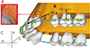
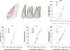
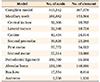
Ten-node tetrahedron elements were used to construct teeth, brackets, PDLs, alveolar bone, and archwires (Table 1). The teeth were brought into contact with adjacent teeth at a contact point and each tooth was allowed to move independently. The PDLs, which have an hourglass shape naturally, had a uniform thickness of 0.2 mm, as was used in previous FEM studies.16 The ligament layer was further divided into two uniform layers of 0.1-mm thickness in this study (Figure 1A). The alveolar bone crest was formed 1.0 mm below the cemento-enamel junction with a curvature that provided sound alveolar bone support (Figure 1B).
Brackets were attached to each tooth using the dimensions of Micro-arch® brackets (Tomy Co., Tokyo, Japan), with slots located on the facial axis of each crown.17 Direct contact between the bracket base and the tooth surface was set with no gap between them.18 Archwires were modeled and produced separately as stainless steel (SS) beam elements. No clearance between the archwire and bracket interface was allowed to eliminate the effect of unrestricted rotation of the archwire within the slot.
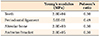
All teeth, brackets, PDLs, alveolar bones, and archwires were assumed to have isotropic and homogenous linear elasticity. Teeth and alveolar bones were assumed to have a single, homogenous structure without a distinction between enamel and dentin or between cortical and cancellous bone.19 Young's modulus and Poisson's ratio of elements were set based on previous studies (Table 2).2919
Simulation of archwire stiffness and friction
For the interface between the archwire and brackets or molar tubes, a surface contact was used instead of a gap contact, as had been employed in previous FEM studies.9 Because the surface contact is highly nonlinear in FEM, analytical procedures for a given load condition were repeated to obtain convergent results. The coefficient of friction was applied to second premolar brackets and the first and second molar tubes in four 0.1-µm steps, from 0 to 0.3 µm, named F0, F1, F2, and F3, respectively.562021 Four types of archwires were used in the present experiment: 0.016 × 0.022-inch (in) SS (W1), 0.017 × 0.025-in SS (W2), 0.019 × 0.025-in SS (W3), and a rigid body (W4) as the control, which showed no deformation.
Orthodontic miniscrews were used to apply a retraction force to the anterior segment and placed in the interradicular space between the second premolar and the first molar at a height of 8 mm from the archwire in the apical direction, accounting for the average tooth height and level of the mucogingival junction in a healthy person (Figure 1B).22 The retraction point was located between the lateral incisor and the canine, as has been described previously,23 and the vertical position was set to the level of the archwire. To perform anterior segment retraction, retraction forces of 150 g per side were applied to retraction points on the archwire with orthodontic miniscrews.
Interpretation of finite element analysis
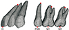
A standard coordinate system was constructed with the x-axis corresponding to the anteroposterior direction; the y-axis, to the superior-inferior direction (vertical displacement); and the z-axis, to the bucco-palatal direction. The anterior direction of the x-axis, apical direction of the y-axis, and lateral direction of the z-axis were designated as positive (Figure 1C). Tooth displacement was compared by assessing the x, y, and z coordinates. Tooth axis change and the rotation of the posterior occlusal plane (the connecting line of crown reference points between the second premolar and the second molar) were also examined in accordance with archwire stiffness and friction. Central incisors were compared based on the midpoint of the incisal edge and root apex; second premolars were compared based on the central point of two cusp tips and root apex; and the first and second molars were compared based on the central point of four cusp tips and of the root apices (Figure 2). For convenience of analysis, each coordinate (corresponding to a displaced tooth reference point) was compared to its initial coordinate; displacement patterns were visualized under 50× magnification for the anterior teeth, 1,000× magnification for the posterior teeth, and 1,500× magnification for the posterior occlusal plane.
Changes in the position of the center of resistance of the central maxillary incisor and first molar
The CR of the maxillary central incisor and first molar were set based on the coordinates used in previous studies.2425 CR displacement was measured as the difference between the initial and post-displacement coordinates.
A general-purpose finite element program, ANSYS 11 (Swanson Analysis System, Canonsburg, PA, USA), was used to calculate and visualize the results of computational and comparative FEM analyses.
RESULTS
In all conditions tested in the present study, initial displacement patterns of the maxillary posterior and anterior segments exhibited backward rotation, regardless of archwire stiffness or friction; this indicated the moment of force possibly caused by the discrepancy between the force vector and the location of the CR of the whole arch. All conditions except for the simulating rigid body (W4) produced differential levels of displacement between the anterior and posterior segments, implying deformation of the working wire.
Effect of archwire stiffness
With low-stiffness archwires (W1 and W2), differences in rotation between the anterior and posterior segments were greater than those with high-stiffness archwires (W3 and W4).
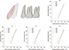
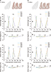
With respect to the incisor displacement (Figure 3; 50× magnification), extrusion of the incisor tip and backward rotation of the incisor axis were greatest with the lowest-stiffness archwire (W1) at any friction level. As the archwire stiffness increased, the displacement amount decreased. In contrast, the posterior segment exhibited the least backward rotation with the lowest-stiffness archwire (Figure 4; 1,000× and 1,500× magnification for the posterior teeth and posterior occlusal plane, respectively). Increased stiffness resulted in greater backward rotation of the posterior segment with extrusion of the second premolar crown and intrusion of the second molar crown. As archwire stiffness increased, the displacement amount also increased.
Effect of friction
With each given level of archwire stiffness, differences in rotation between the anterior and posterior segments decreased relative to the increase in friction (from level F0 to F3). There were minimal differences between W1 and W2 at any friction level.
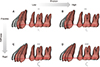
Regarding incisor displacement (Figure 5; 50× magnification), extrusion of the incisor tip and backward rotation of the incisor axis were greatest with the lowest friction level (F0) across all archwire stiffness levels. As the friction level increased, the displacement amount decreased. The posterior segment also exhibited various displacement patterns (Figure 6; 1,000× and 1,500× magnification for the posterior teeth and posterior occlusal plane, respectively). In particular, the effect of friction was not remarkable in W1 and W2. However, in W3, all friction conditions resulted in an increased posterior displacement of the posterior segment, in comparison with the friction conditions in W1 and W2. Moreover, increased friction resulted in even greater backward rotation of the posterior segment with extrusion of the second premolar crown and intrusion of the second molar crown (Figure 6B). In W4, all friction conditions led to a remarkable backward rotation of the posterior segment, and the amount of rotation and extrusion of the posterior occlusal plane decreased as friction increased. Taken together, these results indicate that low friction caused the least backward rotation at each archwire stiffness.
Displacement of the center of resistance
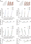
To understand the actual spatial displacement of the representative tooth in each anterior and posterior segment, CR displacement patterns for the maxillary central incisors and first molars were evaluated. Table 3 shows the anteroposterior (x) and vertical (y) displacement of each CR. In summary, compared to resting conditions, the relatively low stiffness archwires (W1 and W2) resulted in less displacement than did the high stiffness archwires (W3 and W4). The greatest amount of displacement occurred with the rigid body and the highest level of friction (W4 and F3).
DISCUSSION
Securing the stabilization of anchorage segments has long been a major issue in clinical orthodontics. Although the miniscrew has played a crucial role as a temporary anchorage device, displacement of the moving (anterior) and anchor (posterior) segments has not been clarified. Therefore, using nonlinear FEM analysis, we investigated the response of the posterior segment under varying archwire stiffness and friction levels in sliding mechanics using miniscrews.
Nonlinear FEM analysis has become more common than conventional linear analysis on the basis of many studies about biomechanical properties of intraoral structures and advancements in computing systems.13 In order to use a nonlinear analysis in the present study, the FE model was further refined to verify the effects of archwire stiffness and friction level. Specifically, a second-order FEM model using a ten-node tetrahedron element was used, instead of a conventional four-node tetrahedron element. In addition, for more accurate tooth displacement analysis, the PDL used in this study was modeled using two layers instead of the conventional one layer (Figure 1A).
For simulation of friction, we established a contact relationship between the archwire and brackets using a surface-to-surface contact rather than a conventional gap contact. The gap contact cannot reproduce interface surface or resistance in the tangential direction, in which friction could not be fully expressed.9 By using surface-to-surface contact, we were able to simulate friction by allowing a loading force to be transmitted in the tangential direction as well as in the normal direction within the bracket slot; moreover, we could simulate tooth displacement under various friction levels.
The unexpected movement of the posterior segment is presumably caused by the connection between the anterior and posterior segments by a semi-rigid wire.1011 Therefore, as described in the results above, it is not surprising to observe rotation of the whole maxillary arch in response to a linear force, primarily on the basis of the distance between the CR and force vector.5 In addition, the extent of posterior segment displacement was dependent on archwire stiffness and friction level (Figures 4 and 6).
Displacement of the anterior segment caused by the retraction force can be transmitted to the posterior segment via a continuous archwire, as described in previous studes.1126 The present study also exhibited similar results, which depended on the archwire stiffness (Figure 4). Low-stiffness archwires showed the least posterior segment displacement, in comparison with high-stiffness archwires. Vertical bowing of the archwire caused by the retraction force was large with the least stiff archwire; this implies that the influence of the anterior segment displacement on the posterior segment might not be significant. In contrast, if the elastic deformation of the archwire was decreased, the anterior segment displacement might have more influence on the posterior segment via a continuous wire. Given this, the posterior segment rotated backward along the rotation of the anterior segment.
Friction can hinder the archwire from sliding through the bracket slots, by which a part of the retraction force can be transmitted to the posterior segment. Consequently, friction may cause distal and vertical displacement of the posterior segment according to the relationship between the force vector and the CR.272829 In this study, there was small amount of posterior tooth displacement in W1 and W2. In contrast, in W3 and W4, the same level of friction caused comparatively large change (Table 3, Figure 6). This phenomenon could not be simply explained by classical surface friction only. In terms of restriction to sliding, binding in the archwire-bracket couple should be considered as another contributing factor. This binding is associated with archwire stiffness; a more stiff archwire may exhibit higher binding.30 Thus, low-stiffness archwires (W1 and W2) seemed to show a reduced binding effect on the posterior segment because of the comparatively large elastic deformation.
In W4 (rigid body without deformation), the amount of backward rotation and extrusion of the posterior segment decreased with friction changes, which showed a different displacement pattern compared with other flexible wires (Figure 6). It seemed that the anterior segment position, reduced rotation and extrusion due to friction, had directly affected the posterior segment position. Moreover, the retraction force, which had a posterior and upward direction, may also affect the posterior segment position via the rigid body. Taken together, the results indicated that overall displacement of the posterior segment was more pronounced with high stiffness and high friction (Figure 7).
CR displacements of the central incisor and first molar, which were respectively representative of the anterior and posterior segments, were assessed to compare actual spatial displacement of the teeth. In most stiffness and friction conditions, the amount of backward rotation was associated with the amount of CR displacement, as if greater rotation may be synonymous with greater posterior displacement of the first molar. In the rigid body (W4), however, increased friction caused reduced posterior “tipping” of the posterior teeth (Table 3, Figure 6). Thus, in W4, the reduced tipping with increased fiction was an expression of the increased true distal displacement of the posterior segment, possibly due to its resistance to sliding through the bracket slot. Taken together, these findings indicate that increased friction may be related to increased displacement of the posterior segment.
In all conditions without exception, the maxillary central incisor showed lingual tipping with various magnitudes, according to the archwire stiffness and/or friction; this is similar to previous studies.25 Notably, increased archwire stiffness and friction causes reduced tipping. However, within the limits of this study, lingual tipping may have been inevitable due to the inherent distance between the CR of the incisor segment and the line of force vector. With respect to incisor axis control, additional measures, such as lever arms, an additional moment on the wire or bracket slot, and miniscrew position may be suggested as alternatives.257 Upadhyay et al.,4 in their randomized controlled trial for en-masse retraction with miniscrew, stated that the displacement of the posterior segment due to friction would be beneficial in both anterior tooth control and vertical profile problems. Nevertheless, it is difficult to predict and control the amount of displacement, and the clinician must be prepared for that change. Especially for cases without vertical problems, a stable posterior segment anchorage may play an important role in preventing the rotation of not only the anterior tooth but also the entire dentition.5 Thus, it is essential to understand the various biomechanical factors that can affect the stability of the posterior segment.
A stiff archwire is recommended to prevent bowing of the archwire and to control the anterior segment in sliding mechanics.2 A deformed archwire can be returned to its initial shape by elastic restoration according to the degradation of the retraction force.1012 Therefore, if force consistency and reactivation interval are ensured, low-stiffness archwires can be more adequate for en-masse retraction, as they are less susceptible to friction change than are high-stiffness archwire. Meanwhile, for the total arch distalization or intrusion with miniscrew, a high-stiffness archwire may be more advantageous than a low-stiffness wire (Figure 7).
The findings of this study suggest an alternative mechanical condition with respect to the stabilization of the dental arch in sliding mechanics with miniscrews. The initial displacement pattern of the posterior segment was associated with the archwire stiffness or friction levels under the same force vector condition. Although, this study has a limitation that the findings may not accurately reflect clinical orthodontic movements, it will provide helpful information for the influence of archwire stiffness and friction on posterior segment stability. To build on this further, long-term tooth movement with additional biomechanical conditions will be necessary in future studies.
CONCLUSION
In the present study, we were able to derive the following conclusions on the basis of tooth displacement patterns with the use of varying archwire stiffness and friction application during en-masse retraction using orthodontic miniscrews.
1. Anterior segment retraction via sliding mechanics using orthodontic miniscrews caused backward rotation of the posterior segment, regardless of archwire stiffness or friction.
2. The posterior segment exhibited the least backward rotation with the lowest archwire stiffness (W1) at all friction levels. With increasing archwire stiffness, the rotation increased (Figure 4).
3. The posterior segment exhibited the least backward rotation with the lowest friction (F0) at all archwire stiffness levels. With increasing friction level, the rotation increased (Figure 6).
Within the limitations of our study, these findings collectively suggest that posterior segment displacement may be unavoidable; however, reducing the stiffness and friction of the main archwire may minimize unwanted rotation.

 XML Download