

 PDF
PDF ePub
ePub Citation
 Print
Print


INTRODUCTION
Various treatment methods have been introduced to correct Class II malocclusion, depending on the severity of the discrepancy. These treatments include orthopedic treatment, premolar or molar extraction, multiloop edgewise arch wire (MEAW) technique,12 intermaxillary elastics, maxillary molar distalization combined with headgear or intraoral appliances, such as superelastic NiTi wires,3 distal jets,4 and molar sliders,5 orthodontic mini-implants (OMI),67 and surgical procedures.
Arch wires with continuous tip-back bends, such as MEAW128 or compensating curved arch wires,91011 together with intermaxillary elastics, have been used for camouflage treatment in patients with mild or moderate skeletal discrepancies. In Class II malocclusion, these tip-back bends and intermaxillary elastics have been traditionally used to obtain distal movement and distal crown tipping of maxillary teeth.
Several studies281012 have examined the tooth displacement achieved by these treatments by means of three-dimensional (3D) finite element analysis812 or two-dimensional (2D) analysis using lateral cephalometric radiographs.210 However, these methods of analysis have limitations. 3D finite element analysis is not an actual treatment result; further, lateral cephalometric radiography has the disadvantage that it is difficult to use to obtain a reproducible landmark because of the positional change of the teeth with respect to the head rotation1314 and the overlap of anatomical structures.15 In addition, it is only possible to use it to analyze the anteroposterior and vertical displacements; it is impossible to use it to analyze the lateral displacement.
3D virtual models have become increasingly widely used in orthodontics as 3D model scanners and software programs have been developed. Thus, analysis of 3D tooth movement has become possible by mathematical superimposition of pre-treatment (T0) and post-treatment (T1) models.1617 However, there has been no research on the use of superimposition of 3D virtual models to evaluate dentitional changes caused by arch wires with continuous tip-back bends or compensating curve together with intermaxillary elastics.
The purpose of this study was to investigate the 3D changes of maxillary dentition in Class II malocclusion treatment using arch wires with continuous tip-back bends or compensating curve, together with intermaxillary elastics, by superimposing pre- and post-treatment 3D virtual models.
MATERIALS AND METHODS
Subjects
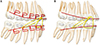
The study was conducted with 20 patients (2 men and 18 women; mean age 20 years 7 months ± 3 years 9 months; A point-Nasion-B point angle, 4.83 ± 2.52°; Frankfort-Mandibular plane angle, 29.03 ± 6.47°; overjet, 4.60 ± 1.50 mm; overbite, 2.32 ± 1.55 mm, crowding in the maxillary arch, 1.60 ± 1.32 mm; average treatment period, 24.15 ± 5.61 months) who had undergone orthodontic treatment at Wonkwang University Dental Hospital (Iksan, Korea) between January 2009 and January 2019. The inclusion criteria for the subjects were as follow: 1) patients who were expected to have no residual growth; 2) patients with complete permanent dentition, Class II division 1 malocclusion, and slight to moderate crowding before treatment; 3) patients who received nonextraction Class II treatment using a 0.016 × 0.022-inch (in) MEAW with continuous tip-back bends or a 0.016 × 0.022-in titanium molybdenum alloy (TMA) ideal arch wire with a compensating curve, together with intermaxillary elastics (anterior vertical elastics; 3/16 in, 6.5 ounce [oz] and occasionally Class II elastics; 5/16 in, 6.5 oz), after alignment and leveling (Figure 1); and 4) patients who had a Class I canine and molar relationship, normal overbite, and overjet at the end of treatment. None of the subjects had degenerative temporomandibular joint disease or any dental prosthetic treatment during orthodontic treatment. This study was approved by the Institutional Review Board of Wonkwang University Dental Hospital (WKDIRB201903-04).
Superimposition of three-dimensional virtual maxillary models
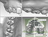
Maxillary models at T0 and T1 were scanned using a 3D model scanner with an accuracy of 10 µm and a 2.0-megapixel camera (Freedom HD; DOF Inc., Seoul, Korea) and a 3D reverse modeling software program (Rapidform 2006; INUS Technology, Seoul, Korea). To evaluate tooth movement patterns, the T0 and T1 3D virtual models were superimposed on the palatal rugae, especially the third medial rugae, and the midline raphe using the 3D surface-to-surface matching function (best-fit method) of Rapidform 2006 software (Figure 2).1617
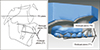
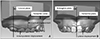
To prevent errors of superimposition, the angles between the Frankfort horizontal plane and the maxillary occlusal plane established by the maxillary central incisor edge and the mesiobuccal cusp tip of the maxillary first molar at T0 and T1 were measured on the lateral cephalometric radiograph, and the differences between the occlusal plane angles at T0 and T1 were calculated. The occlusal planes were then constructed on 3D virtual models at T0 and T1 to pass through the midpoint of the right and left maxillary central incisor edges and the mesiobuccal cusp tip of the right and left maxillary first molars. The angular difference between the occlusal planes at T0 and T1 of the 3D virtual model was compared with that of the lateral cephalometric radiograph (Figure 3). If the angular difference between the 3D virtual model and the lateral cephalometric radiograph was greater than 5°, superimposition of the 3D virtual models was reattempted to correct the error.18
Measurements
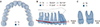
The reference points, lines, and planes used for measurements in the present study are shown in Figure 4. The facial axis (FA) points19 of maxillary teeth have been used as reference points for measurement in previous studies718 because incisal edges or cusp tips could be changed during orthodontic treatment. Therefore, the FA points were used as the reference points for all measurements in our study. The horizontal plane was set at the uppermost part of the midpalatal area, parallel to the occlusal plane at T0. The coronal plane was constructed to pass through the FA points of the right and left maxillary second molars, perpendicular to the horizontal plane. The midsagittal plane was constructed to pass through the midpoint of the FA points of the right and left maxillary central incisor, perpendicular to the horizontal and coronal planes (Figure 4D).
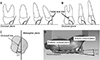
The linear measurements included the anteroposterior, vertical, and lateral displacements of the maxillary central incisor (U1), canine (U3), second premolar (U5), first molar (U6), and second molar (U7) (Figure 5). The anteroposterior displacement was measured as the distance from the FA point to the coronal plane. When the tooth was located posterior to the coronal plane, the distance was taken as negative (Figure 5A). The vertical displacement was measured as the distance from the FA point to the horizontal plane (Figure 5A). The lateral displacement was taken as the distance from the FA point to the midsagittal plane (Figure 5B).
The angular measurements included the inclinations of U1, U3, U5, U6, and U7; the angulations of U3, U5, U6, and U7; and the rotations of U6 and U7 (Figures 6A–6C). The angles of the anterior occlusal plane (AOP) and posterior occlusal plane (POP) and the angular difference between the AOP and POP were also measured (Figure 6D). Angular measurements were performed using a projected line of the FA line on the reference planes. The inclinations were taken as the angle between the occlusal plane and the projected FA line of U1 on the midsagittal plane and the angles between the occlusal plane and the projected FA lines of U3, U5, U6, and U7 on the coronal plane (Figure 6A). The angulations were the angles between the occlusal plane and the projected FA lines of U3, U5, U6, and U7 on the midsagittal plane (Figure 6B). The rotations were the angles between the midsagittal plane and the projected occlusal lines of U6 and U7 on the horizontal plane (Figure 6C). The AOP angle included the anterior angle between the horizontal plane and the projected AOP (the line connecting the FA points of U1 and U5) on the midsagittal plane (Figure 6D). The POP angle was measured as the anterior angle between the horizontal plane and the projected POP (the line connecting the FA points of U5 and U7) on the midsagittal plane (Figure 6D). The angular difference between AOP and POP was taken as the POP angle minus the AOP angle. All of the measurements were performed using Rapidform 2006 software.
Statistical analysis
The required total sample size was calculated using the G*Power software, ver. 3.1.9.4 (Franz Faul; Universität Kiel, Kiel, Germany). The results showed that more than 15 patients were required to obtain a significant difference with a typical two-tailed statistical analysis when the α value for significance was set to 0.05 and the force (1−β) was set to 0.8.
All of the superimpositions of the lateral cephalometric radiographs or 3D virtual models and measurements were performed by a single observer (J.Y.L). To assess in traobserver reliability, the reference points for 7 patients at T0 and T1 were digitized twice, at a 4-week interval, by the same observer (J.Y.L). The intraclass correlation coefficients (0.863–0.998) indicated excellent reproducibility of the reference point identification.
Twelve of the subjects were treated using 0.016 × 0.022-in MEAW with continuous tip-back bends, and 8 of the subjects were treated using 0.016 × 0.022-in TMA ideal arch wire with a compensating curve. However, the measurements for all of the subjects were pooled because there was no significant difference detected in the treatment results for the 2 types of arch wires. The mean values for the right and left sides were used for analysis because there was no significant difference detected in the values between both sides for T0 and T1. The result of Shapiro-Wilk tests showed that the mean values of the measurements fit normal distributions. Therefore, paired t-test was used to compare the T0 and T1 values of each variable. All of the statistical analyses were performed using IBM SPSS Statistics ver. 24.0 (IBM Corp., Armonk, NY, USA), and a 95% confidence level (p < 0.05) was considered statistically significant.
RESULTS
Three-dimensional linear displacements of teeth
As Table 1 and Figure 7A show, in terms of anteroposterior displacement, all of the measurements indicated significant posterior displacement. The posterior displacement of the maxillary central incisor was 0.66 ± 0.86 mm (p < 0.01). The maxillary canine, second premolar, and first molar were moved backward by 0.97 ± 0.88 mm, 0.99 ± 0.60 mm, and 0.99 ± 0.66 mm, respectively (p < 0.001). The second molar showed the largest posterior displacement of 1.40 ± 0.67 mm (p < 0.001). All teeth except the second molar were significantly displaced laterally. The lateral displacements of the maxillary central incisor, canine, and second premolar were −0.31 ± 0.35 mm, −0.40 ± 0.62 mm, and −0.63 ± 0.83 mm, respectively (p < 0.01). The mean lateral displacement of the first molar was −0.57 ± 0.92 mm (p < 0.05). In terms of vertical displacement, the maxillary central incisor and canine were extruded by −0.56 ± 1.13 mm (p < 0.05) and −0.44 ± 0.67 mm (p < 0.01), respectively. The maxillary second premolar and first molar showed significant intrusive movement (0.66 ± 0.56 mm and 0.63 ± 0.56 mm, respectively; p < 0.001). There was no significant vertical displacement of the maxillary second molar (Table 1, Figure 7B).
Three-dimensional angular displacement of tooth and occlusal plane
As Table 2 and Figure 7 show, there were significant changes of inclination in the maxillary second premolar and first molar. These teeth were tilted buccally by 4.21 ± 5.24° (p < 0.01) and 4.50 ± 3.54° (p < 0.001), respectively (Figure 7C). In the case of the mesiodistal angulation, the mean distal crown tipping of the maxillary canine was 2.01 ± 3.96° (p < 0.05), and that of the maxillary first molar was 3.77 ± 4.88° (p < 0.01). The second premolar showed the largest distal crown tipping of 7.18 ± 5.69° (p < 0.001) (Figure 7B). With regard to the rotation of molars, only the maxillary first molar exhibited significant distal-in rotation, with a mean value of 2.87 ± 3.55° (p < 0.01) (Figure 7A). There was no significant change in the angular measurements of the maxillary second molar (Table 2).
Significant changes were noted in all measurements relative to the occlusal plane angle. The AOP rotated clockwise (−2.93 ± 2.95°, p < 0.001), while the POP was rotated counterclockwise (1.83 ± 2.29°, p < 0.01), resulting in a significant reduction in the angular difference between the AOP and POP (4.76 ± 3.70°, p < 0.001; Table 2, Figure 7B).
DISCUSSION
In the present study, we analyzed the 3D changes of maxillary dentition in patients with Class II malocclusion by superimposing 3D virtual models before and after treatment using MEAW with continuous tip-back bends or a TMA ideal arch wire with a compensating curve, together with intermaxillary elastics. We observed posterior displacement of the maxillary teeth with distal tipping of the posterior teeth, expansion of the maxillary arch with distal-in rotation of the first molar, and reduced occlusal curvature as a result of extrusion of the maxillary central incisor and intrusion of the maxillary second premolar. The second molar only showed posterior displacement (Figure 7).
Traditionally, tooth displacement associated with treatment using an arch wire with continuous tip-back bends or a compensating curve and intermaxillary elastics has been evaluated using 3D finite element analysis812 or lateral cephalometric analysis.210 However, 3D finite element analysis cannot identify the actual treatment effects because it uses constructed models. Lateral cephalometric radiography is limited in that it is difficult to use it to obtain reproducible and accurate landmarks, because of positional changes of teeth associated with head rotation1314 and the overlap of the anatomical structures.15
Recently, 3D virtual models have been introduced to assess tooth movement in three dimensions by superimposition of pre- and post-treatment models.161718 3D virtual model analysis has the advantage that it makes it possible to obtain more accurate landmarks and evaluate the lateral displacement of dentition, as well as anteroposterior and vertical displacement. In superimposing pre- and post-treatment 3D virtual models, the palatal rugae, especially the third medial rugae,172021 and the midpalatal area between the maxillary first and second molars1822 are regarded as stable structures during orthodontic treatment. Accordingly, this area was selected in this study as a stable landmark for superposition of preand post-treatment 3D virtual models.
According to 3D finite element analysis results obtained in a previous study,23 when MEAW with tip-back bends was applied alone, the main treatment results were labioversion and intrusion of the maxillary incisor. However, when an arch wire with tip-back bends was used with intermaxillary elastics, intrusion of the maxillary incisor was counteracted by the intermaxillary elastics, and intrusion of the maxillary posterior teeth was increased, which was consistent with our results.812 In our study, we detected extrusion of the maxillary anterior teeth (0.44–0.56 mm) and intrusion of the maxillary posterior teeth (0.63–0.66 mm).
In another 3D finite element analysis study of the effects of tip-back bends,12 the tooth displacement was concentrated in the anterior part of the maxillary dentition when Class II intermaxillary elastics were used with MEAW or an ideal arch without tip-back bends. However, when tip-back bends were added to flat MEAW or ideal arch wires, the posterior translation and lingual tipping of the anterior teeth were reduced and the posterior translation and distal tipping of the posterior teeth were increased as the amount of tip-back bends was increased.12 Our study yielded similar results in that the posterior displacement of the maxillary posterior teeth (0.99–1.40 mm) was larger than that of the maxillary anterior teeth (0.66–0.97 mm). There was also distal crown tipping of the maxillary posterior teeth (3.77–7.18°) without significant palatal tipping of the maxillary central incisor.
In a lateral cephalometric analysis study by Liu et al.,2 treatment results were observed for MEAW with tip-back bends and intermaxillary elastics in patients with Class II malocclusion. The results were similar to those observed in our study in that the tip of the maxillary central incisor exhibited posterior displacement (1.7 mm) and extrusion (1.1 mm) with palatal crown tipping (4.7°). However, the displacement of the maxillary first molar was not consistent with that observed in our study. Extrusion (0.5 mm) and mesial tipping (2.2°) of the maxillary first molar without significant posterior displacement were observed in the cited study. This was because the arch wire in that study had a step bend for extrusion of the posterior teeth, as well as tip-back bends. Interestingly, most of the patients exhibited anterior displacement of the mandible after treatment in that study.2
Previous 3D finite element analyses812 and lateral cephalometric analysis2 only evaluated anteroposterior and vertical displacement. In our study, lateral displacement was also measured, and lateral displacement of the teeth, except the second molar, was found to be 0.31–0.63 mm. Buccoversion in the second premolar (4.21°) and first molar (4.50°) and distal-in rotation of the first molar (2.87°) were also observed in our study.
The maxillary second molar exhibited only posterior
displacement in our study. The maxillary second molar seemed to be inadequately controlled for other displacements, such as intrusion, lateral movement, and angular displacements, because the maxillary second molar was located at the end of the arch wire, which was not rigid enough. Because the second molar moved only in the posterior direction, while the other maxillary teeth moved in three dimensions, it was thought that the posterior displacement of the maxillary second molar (1.40 mm) was larger than that of other maxillary teeth (0.66–0.99 mm).
A study24 that evaluated the significance of the cant of the POP in Class II division 1 malocclusions reported that Class II division 1 malocclusions tended to have a steep POP. In addition, there was a severe occlusal curvature in the maxillary dentition.24 The authors of that study suggested that vertical control of the posterior teeth was important in skeletal Class II division 1 treatment because the vertical aspect of the occlusion could interfere with mandibular function in relation to the sagittal condylar path and the guidance of the lingual concavity of the maxillary incisor.24 In our study, the occlusal curvature was flattened after treatment. The decrease in curvature was caused by intrusion of the second premolar and the first molar. This also resulted in decreased POP inclination.
Some 3D virtual model studies have reported on changes in the maxillary dentition of Class II malocclusion treated with OMI67 or premolar extraction.25 A study7 that evaluated maxillary tooth movement in Class II malocclusion treated without extraction by buccal OMI showed posterior movement of the maxillary teeth (0.98–2.40 mm), increased arch width (1.93–2.25 mm) (except for the second molar), and distal-in rotation of molars (3.0–4.5°). As a result, the V-shaped maxillary arch was transformed into a U-shaped arch.7 This displacement pattern was similar to that observed in our study.
However, in contrast to our study results, only extrusion of the maxillary second molar was significant (0.86 mm) in the previous study.7 In addition, the amounts of anteroposterior and lateral displacement were larger than those observed in our study. The reason for this is that Class II malocclusion should be corrected by displacement of the maxillary teeth only, without compensatory movement of the mandibular teeth, when using OMIs in the maxillary arch. The results of another 3D virtual model study25 of Class II division 1 malocclusion treated with first premolar extraction also differed from ours. In that study, the maxillary anterior teeth were intruded by 0.5–0.8 mm, and the maxillary posterior teeth were extruded (0.5–1.5 mm) and contracted (0.8–1.4 mm). In addition, there were palatoversion of the maxillary incisors (3.2–6.1°), and mesial tipping (4.0–6.7°) and mesialin rotation (3.0–5.1°) of the maxillary posterior teeth. These resulted from biomechanical differences in force application between total arch distalization and extraction space closure. The result of these 3D virtual model studies will help clinicians to understand the differences in dentitional changes that occur during correction of Class II malocclusion by means of various treatments.
When a mandibular 3D virtual model was approximately superimposed on the maxillary reference region of the palate, with proper consideration of the occlusal relationship with the maxillary dentition, the overjet at the FA points was decreased by 2.5 mm after the treatment, and the corrections of the canine relationship and the molar relationship were 2.0 mm and 1.5 mm, respectively. However, there were no significant changes in overbite and no significant skeletal changes.
A few limitations in our study should be noted. First, Class II malocclusion was corrected by not only posterior displacement of the maxillary teeth but also displacement of the mandibular teeth or the mandible itself. When Class II malocclusion was corrected by an arch wire with continuous tip-back bends or a compensating curve, together with intermaxillary elastics, it caused compensatory changes in mandibular dentition, resulting in occlusal relationship changes.
Thus, this study was limited in that measurements of simultaneous displacement of mandibular teeth was impossible, because of the lack of a reference region for use with the mandibular 3D virtual model. Further studies are needed to investigate the best method for superimposing the mandibular dentition, and it is also necessary to provide more details on the mechanism for correcting Class II malocclusion by measuring the change in mandibular dentition accurately. The results of our study will help clinicians to understand the mechanism of correction of Class II malocclusion using an arch wire with continuous tip-back bends or a compensating curve, together with intermaxillary elastics.
CONCLUSION
1. When arch wires with continuous tip-back bends or compensating curves, together with intermaxillary elastics, were applied to patients with Class II malocclusion, the maxillary dentition was retracted and expanded with distal-in rotation of the first molar.
2. Extrusion of the maxillary incisor and canine and intrusion of the maxillary second premolar and first molar were observed and contributed to reduction of the occlusal curvature.
3. The maxillary second molar exhibited only posterior displacement.


 XML Download