

 PDF
PDF ePub
ePub Citation
 Print
Print


Physiological cervical spine kinematics involves not only the amount of motion but also the nature of motion. The nature of motion, known as quality of motion, is difficult to evaluate clinically, although it can be assessed by measuring the mean instant center of rotation (ICR).12345) Characterizing the path of ICR during cervical spine movement is of interest because of the increased use of various artificial disc devices with different kinematics to mimic normal cervical motion.67)
The locations of ICR in the subaxial cervical spine have been measured conventionally by using plain radiographs collected at the ends of the range of motion (ROM).4589) These static locations of the ICR cannot effectively represent how the ICR changes during dynamic motion and have limitations, including differences in ROM measurement due to dynamic muscle-driven movement in vivo,510) as well as measurement bias.1112) The need for three-dimensional (3D), in vivo measurements of the spine under dynamic load to interpret more precisely the quality of motion is becoming apparent.91013) Recently, a new technique of measuring the ICR with biplanar fluoroscopy during in vivo cervical motion has been introduced, enabling translation to 3D circumstances with improved accuracy.141516) In this study, we set out to ascertain the locations and possible distribution areas of ICR in the sagittal plane at each subaxial cervical segment during in vivo movements in healthy subjects and to assess the differences in locations from those in previous reports.
METHODS
This study involved three asymptomatic subjects who gave informed consent and Institutional Review Board of Chung-Ang University Hospital (IRB No. C2012241(936)) approved this study. All subjects were men with a mean age of 32 years (range, 30 to 33 years). Computed tomography (1.25 mm in slice thickness) of the cervical spine (C2–7) was performed for each subject and 3D models of each vertebra were created.
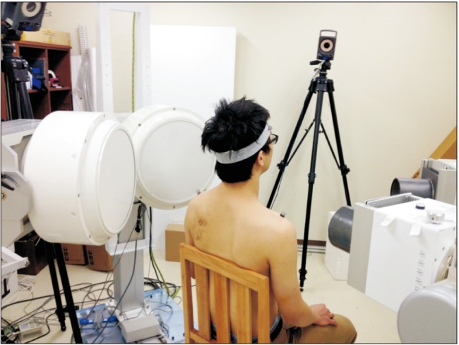
Biplanar fluoroscopic images were collected within a system composed of two focal-spot radiograph tubes (KMC–1400ST; COMED Technologies Inc., Gwangju, Korea) with standard radiologic parameters (50 KV, 10 mA). The images were collected for 2 seconds at 27 frames per second for each trial of continuous flexion-extension (total 54 frames). Dynamic ROM images were collected from two oblique views aligned horizontally and angled at approximately 55° (Fig. 1). Movement started from the neutral position, through full flexion and full extension, and finally back to the neutral position. For standardization of each frame of the continuous trial, the coordinates of ICR were normalized to the static neutral trial, as a reference point. The study protocol using biplanar fluoroscopy for assessing dynamic movement was introduced by Anderst et al.14151617) The minimum change in degree to detect significant movement was set as 2° of change in intervertebral flexion-extension from the helical axis model.
Six-degrees-of-freedom kinematics and finite helical axis models between adjacent vertebrae were calculated in accordance with standard coordinate systems.1819) The ICR was defined as the point at which this 3D axis of rotation crosses the sagittal plane of the inferior vertebra.1416) The anterior-posterior (AP) and superior-inferior (SI) locations of each ICR were defined with respect to the anatomical coordinate system, and the zero point was set at the center of the upper end plate of the lower cervical vertebra in the segment (Fig. 2B). The location of ICR was defined using the (x, y) coordinate system. The x-axis was directed forward along the upper endplate of the lower cervical segments and the y-axis was directed upward perpendicular to the x-axis (Fig. 2A).
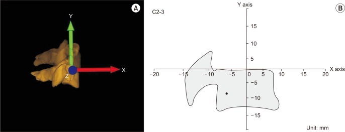 | Fig. 2(A) Three-dimensional reconstruction of the cervical spine from biplanar fluoroscopic projection. The arrow to superior direction represents Y axis; anterior, X axis; horizontal, Z axis. (B) The location of instant center of rotation at the C2–3 segment was calculated by using the (X, Y) coordinate system.
|
The distribution area, distribution circle of the ICR, was drawn for each motion segment by using the mean AP and SI coordinates of the ICR. To evaluate the possible distribution area of the ICR, the distance between all AP and SI coordinates of ICR in each frame and the mean ICR coordinates were calculated (mean absolute deviation), and then a circle with a radius of this mean absolute deviation was drawn with the mean AP and SI coordinates of ICR as its center. This distribution circle marked the borders of the possible distribution area of the ICR. The calculation of the area of distribution circle was performed by using Sketch up 2016 (Trimble Systems, Google, Mountain View, CA, USA), which could measure the area automatically by the integration.
Statistical Analysis
The mean AP and SI coordinates were calculated for each motion segment, and the Kruskal-Wallis test was performed with the Mann-Whitney test for post hoc analysis. A linear mixed-model analysis was performed to find the statistical differences in the path of the ICR according to each motion segment. Bonferroni adjustments were applied to p-values to account for multiple testing. According to the post hoc power analysis for the SI location, the power of this study was 0.802 with an effect size of 0.297. The level of statistical significance was set at p < 0.05.
Go to : 
RESULTS
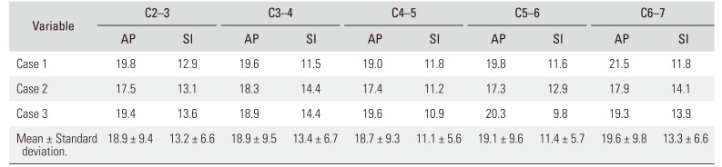
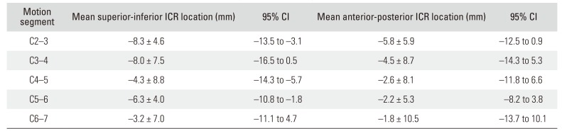
The estimated size of each vertebral body, which was defined as its greatest length, is summarized in Table 1. The overall ROM curves are shown in Fig. 3. The ROM was larger in the C4–5 and C5–6 segments than in the other segments. The mean AP and SI coordinates of each ICR are summarized in Table 2. The mean SI location became progressively more superior from C2–3 motion segment to the C6–7 motion segment, except for the C5–6 segment. A statistically significant difference was found in the mean SI location of ICR (p = 0.015). On post hoc analysis, significant differences were found between the motion of the ICR in segments C2–3 and C6–7. The mean AP locations became progressively more anterior in the lower cervical segments without exception, but the mean AP locations were not significantly different (Fig. 4).
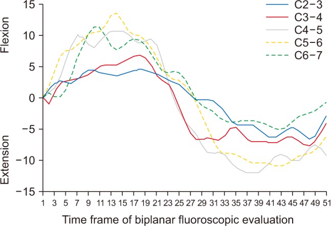 | Fig. 3The overall range of motion in subaxial cervical segments. Positive values mean flexion and negative values mean extension. The greater range of motion was observed in the C4–5 and C5–6 segments.
|
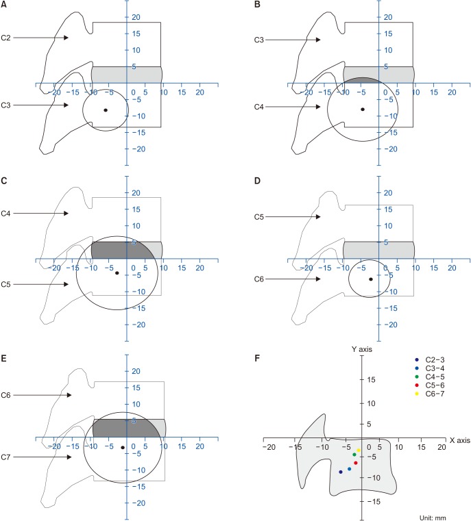 | Fig. 4(A) The radius of circle was measured as 6.3 mm. There was no overlapping area between the circle and intervertebral space in C2–3 segment. (B) The radius of circle was measured as 9.7 mm. The overlapping area was located in the posterior half of intervertebral space in C3–4 segment. (C) The radius of circle was measured as 11.2 mm. The overall posterior area and half of anterior intervertebral space was overlapped by the distribution circle in C4–5 segment. (D) The radius of circle was measured as 5.7 mm. There was no overlapping area between the circle and intervertebral space in C5–6 as in C2–3 segment. (E) The radius of circle was measured as 10.8 mm. The overall intervertebral space was overlapped by the distribution circle in C6–7 as in C4–5 segment. (F) The overall locations of ICR showed a trend of moving progressively superiorly and anteriorly in the lower cervical segments except in C5–6 segment.
|
Table 1
Mean AP and SI Size of Each Vertebral Body
![]()
Table 2
The Mean Location of ICR in Each Cervical Motion Segment
![]()
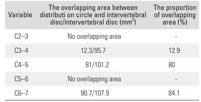
The distribution circle of ICR was mainly located in the body of lower cervical vertebra and shifted progressively superiorly and anteriorly, moving down to the C6–7 segment; the overlapping area between the intervertebral disc level and distribution circle showed a tendency to increase for each motion segment from C3–4 to C6–7 segment, except for C5–6 segment (Table 3 and Fig. 4). The overlapping area was mainly located in the posterior half in C3–4 segment, but the overlapping area in C4–5 and C6–7 segments increased and more than 80% of intervertebral space was overlapped by distribution circle in those segments (Table 3 and Fig. 4). The mean SI coordinates of C5–6 segment in subject 1 were shown to be different from those of C5–6 segment in subjects 2 and 3 (Fig. 5). The linear mixed-model analysis was not statistically significantly different for the path of ICR according to each motion segment (AP, p = 0.694; SI, p = 0.905).
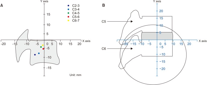 | Fig. 5(A) The location of instant center of rotation of C5–6 segment was changed more superiorly and anteriorly after exclusion of the values of C5–6 segment in subject 1. (B) The overall intervertebral space was overlapped by the distribution circle after exclusion of the values of subject 1.
|
Table 3
The Overlapping Area between Distribution Circle and Intervertebral Disc
![]()
Go to :
DISCUSSION
The most important findings of this study are that the mean locations of ICR were different in each cervical motion segment but tended to move in constant directions with the lower cervical segments during dynamic motion. The mean location of ICR of the C2–3 segment was at the lower posterior quadrant of the geometric border of the C3 and became progressively more superior and anterior until C6–7 segment. The mean location of ICR of the C6–7 segment was just posterior to the center in AP dimension and near the superior endplate of the C7 in SI dimension (Fig. 4). The trend of the mean SI location to move progressively superiorly except for the C5–6 segment was statistically significant (p = 0.015), and the change in the mean AP location moving anteriorly with the lower cervical segment without exception was not statistically significant.
Previous studies using biplanar fluoroscopy14151617) also reported the locations of the ICR in each motion segment: the location was level specific at each cervical motion segment, especially in the SI direction. Anderst et al.16) reported that the SI location of the ICR moved progressively superiorly from the C2–3 segment to the C6–7 segment, showing statistical significance among all motion segments except the C3–4 and C4–5 segments. However, the SI locations of ICR showed constant superior translation from upper to lower cervical segments without exception. These findings were also observed in our study except the C5–6 segment as described in other studies.11516) On the mean AP location in the study of Anderst et al.,16) however, there was no constant tendency of movement with lower cervical segments, and no change or only slightly posterior translation of the location was observed from the C3–4 segment to the C6–7 segment. In our study, the mean AP location became progressively more anterior without exception, even though this was not statistically significant; the locations were eventually found near the midline of the lower vertebral body of C5, C6, and C7. These trends indicate that the mean ICR moved in a constant direction with the lower cervical segment, not only in SI direction but also in AP direction.
The ICR motion paths in our study were not shown as a constant AP line, as in the study of Anderst et al.16): they reported that only the AP location of ICR, not the SI location, could be significantly affected by the angle of intervertebral flexion-extension. Therefore, they reported that the ICR motion paths were different in each motion segment and were shown as a constant line. However, in our study, there was no correlation between the AP locations of ICR and the angle of intervertebral flexion-extension, and the coordination was distributed randomly. Those differences migh have orignated from the methodological differences, the younger age of the subjects of this study, and the number of obtained images per second. Thus, we used the distribution circle to show the possible distribution area of ICRs at each cervical segment, not just to describe a simple path. We expect that the distribution circle could provide more information especially in design of cervical arthroplasty device, such as the radius for sliding prosthesis, to mimic more physiological kinematics. In our results, the overlapping area between the distribution circle and intervertebral space was shown in the posterior half of space in upper motion segments, and the overlapping area increased along with the lower motion segments except C5–6 segment. The coordination value of the C5–6 segment in subject 1 was an outlier (Table 4). When the value of subject 1 was excluded, the mean location of ICR was 5.2 ± 5.1 mm in SI location and 1.3 ± 7.7 mm in AP location, which is closer to the trend of ICR SI location of other segments, and the overlapping area was found 100% of disc space in C5–6 segment after exclusion of subject 1 (Fig. 5). However, further research would be needed to verify this method as an established analysis technique.
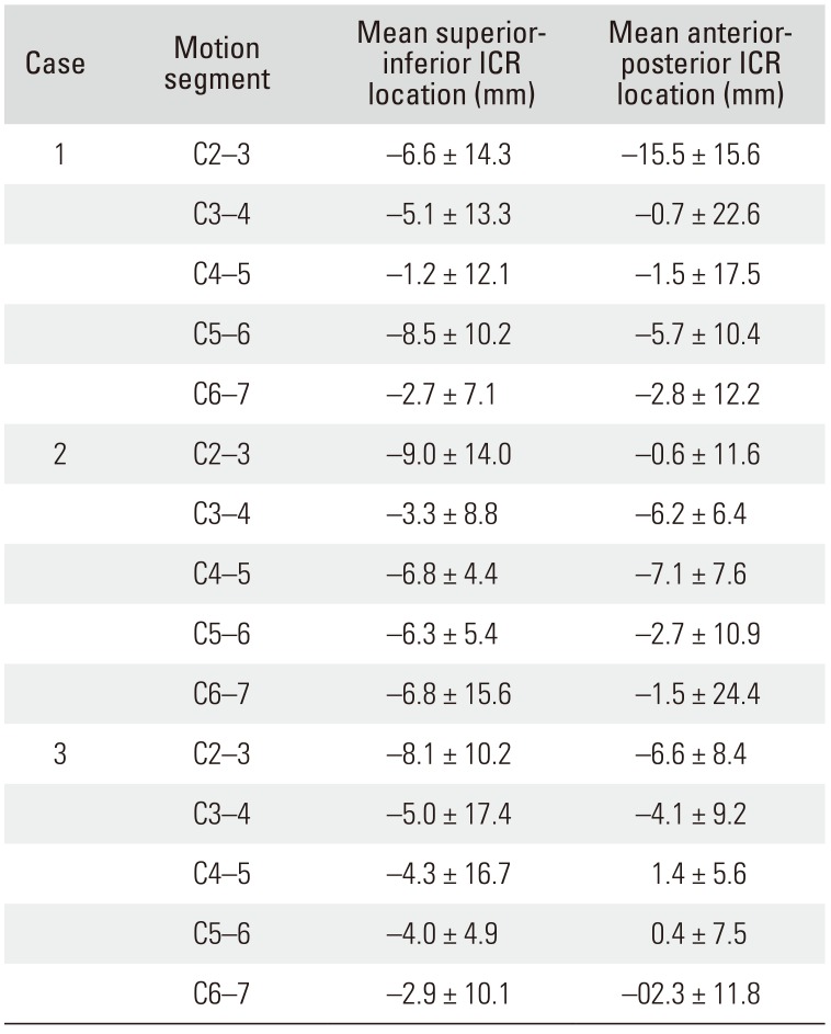
Table 4
The Mean Location of ICR in Each Subject
![]()
On the basis of our preliminary results, the prosthesis for cervical arthroplasty might be designed or implanted with consideration of the level-specific location of the ICR to obtain more physiological motion. Generally, the translation component in cervical sagittal motion leads to a larger inferior shift of the ICR, and the angular rotation component leads to a larger superior shift.1416) Considering the changes of SI location of the ICR according to translation and rotation movements, a cervical arthroplasty design allowing more rotation than translation, such as a constrained or semi-constrained type, could be appropriate in lower cervical segments. In contrast, a design allowing more translation than rotation could be more physiologic in upper cervical segments; this estimation could be supported by the report of Anderst et al.1416) where the change in ICR location in the AP direction during motion increased from the C6–7 segment to the C2–3 segment. Moreover, according to the overlapping area and ICR in our study, the prosthesis in intervertebral level might have more physiological kinematics if it is located in the posterior half in upper cervical segments and if it is located more centrally in lower cervical segments.
Our study has several limitations. First, the number of subjects was small. Therefore, the differences between subaxial segments, especially in the change of mean AP location, may not have shown statistical significance. Second, we had outlier data at C5–6 segment in subject 1. It could be the reason why the trend of superior movement along the lower cervical segments was not observed at C5–6 segment. Further investigation with a larger number of cases will be needed. Third, the included subjects had a relatively narrow range of age and all were men. The results of the ICR might be different in older age groups and in women. Nonetheless, these preliminary findings characterize the change in mean locations of the ICR in each cervical segment and demonstrate the differences in the change of AP locations compared to those in previous reports.
The mean SI locations of the ICR became progressively more superior from the C2–3 segment to the C6–7 segment, except in the C5–6 segment, and the mean AP locations showed a tendency to move progressively anteriorly in the lower segments. In addition, the disc space overlapped by the distribution circle has a tendency to increase along the lower motion segments. These findings could provide a good basis for developing level-specific cervical arthroplasty designs and their intraoperative positioning in disc space.
Go to :
 XML Download