

 PDF
PDF ePub
ePub Citation
 Print
Print


INTRODUCTION
Digital implant impressions (DII) with intraoral scanners (IOS) are a relatively novel, but continuously improving technique. Their popularity is increasing because of various patient-related (increased comfort due to avoidance of impression tray and materials) and dentist-orientated (time and cost savings, digital data storage and analysis, etc.) aspects.1 IOS have supplemented the traditional prosthodontic approach and contributed to the concept of “virtual patient”.
Conventional implant impressions (CII) have been a standard procedure for fixed prosthodontics for a long time. The workflow associated with CII has limitations that affect the efficiency. Selection of tray and impression material, impression technique, time consumption, impression disinfection, transportation, and storage issues are the main reasons for considering alternative impression techniques in fixed prosthodontics.2 DII were proposed as a possible alternative to the conventional workflow a few decades ago.3
The newest technologies of IOS hardware and software are developing rapidly and showing acceptable clinical results for tooth-supported crowns.4 A recent systematic review reported deviations in digital implant impressions of less than 100 µm in mainly in vitro studies.5
In vitro studies allow using true reference data. However, the equipment for obtaining reference data cannot be used in a clinical study and digital impressions generally can be compared only to the conventional ones. In vitro studies do not fully represent the clinical situation, as there are many variables that could affect the accuracy of DII intraorally.
As there are plenty of randomized clinical studies of the accuracy of digital impressions on sound teeth6, scientific literature is lacking data from clinical studies about the accuracy of digital impressions for implant-supported restorations.78910 The aim of this study was to evaluate and compare the digital and conventional dental implant impressions in the clinical setting.
MATERIALS AND METHODS
Twenty-four fixed partial restorations supported by 2 AnyOne implants in six patients (Megagen, Daegu, Korea) were included. All implants were placed in the posterior area of the mouth. Two-unit (n = 7), three-unit (n = 11), and four-unit (n = 6) zirconia restorations were fabricated. The average inter-implant distance was 15.82 ± 5.66 mm. Clinical study was approved by the Vilnius Regional Ethics Committee for Biomedical Research (No 158 200-16-861-370).
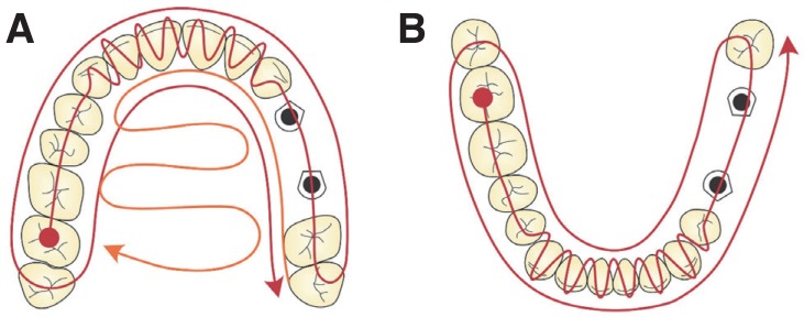
Two different types of implant impressions were performed for each case in random order. A conventional opentray impression technique with splinted transfers using vinylpolysiloxane (Express, 3M, Mapplewood, MN, USA) was made (CII group). A splinting procedure of the impression copings and their verification of passive-fit was applied.11 A digital impression was taken using original scan bodies torqued to the implants at 15 Ncm and a Trios 3 IOS (3Shape; version 1.3.4.2) (DII group). The scanning technique making less than 1,000 images per arch was completed under manufacturer's recommendations. In the maxilla, the scanning started from occlusal surface moving to buccal and palatal surfaces, while in the mandible, the lingual and buccal surfaces were captured after scanning the occlusal surfaces (Fig. 1). Standard tessellation language (STL) files were used for comparisons.
Master models were fabricated from conventional impressions with type IV plaster (FujiRock, GC, Tokyo, Japan) under the manufacturer's instructions and allowed to set at room temperature for 24 hours. A verification jig was used to assess the accuracy of the position of the implant analogues in the master model. Passive fit evaluation techniques, such as finger pressure and Sheffield and screw-resistance tests,12 were used during the verification procedure. After verification of the master model, same scan bodies at the same implant locations and in the same rotational positions were attached to the implant analogues using 15 Ncm torque. Scanning of master models was completed using a D800 (3Shape, Copenhagen, Denmark) laboratory scanner and Dental System software (version 2.9.9.3). After exportation of the STL files, the 3D models were compared with the 3D models obtained from the DII procedure. Implant-supported zirconia restorations were fabricated from the conventional impressions. During all steps of the manufacture and final delivery of the restoration, passive fit was additionally evaluated using the same techniques as were used with the verification jig. As all the restorations were clinically acceptable, master models were additionally confirmed as accurate. Also they were regarded as the best available reference, due to the multiple verification procedures of the master model and final restorations.
The high resolution and high accuracy 3D Computer-Aided Design (CAD) models were imported into Rapidform 2006 (INUS Technology Inc., Seoul, Korea) reverse engineering software. 3D models produced from data captured by the IOS and laboratory scanner were compared with 3D CAD models of scan bodies. Each imported 3D model was checked for the presence of any non-manifold, redundant, crossing, and unstable faces in the imported shell. The positions of reference points were imported for calculations by using data analysis software in Matlab R2014b (The MathWorks, Inc., Santa Clara, CA, USA).
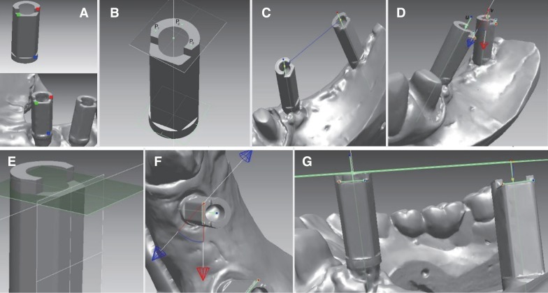
Each 3D model had its own position in space and its own rotation. For the alignment of 3D models, a coarse alignment was applied, and then a fine alignment was performed using iterative closest point (ICP). The coarse alignment approximates the rigid transformation between models. This is a manual step in which a researcher must select three corresponding 3D points on the captured image and original 3D model of the scan body (Fig. 2A). Each pair of corresponding points is represented by a small square in different color.
The fine alignment algorithm is an iterative procedure minimizing the mean square error (MSE) between points of the first model surface and the closest points, respectively, on the other surface. The algorithm represents the geometric transformation that best aligns the original model and the closest points, respectively, on the scan body surface.
The alignment procedure was repeated with other models of the scan bodies.
In the next steps, all processing and measurements were performed using only the high precision 3D CAD models of the scan body. To identify the scan body axis, the section plane was created on the scan body shell. This section plane is perpendicular to the cylinder part direction and a reference vector normal to this reference plane is the axis of the scan body. The center point of the scan body is at the intersection between this axis and the top plane, which can be found by picking three reference points on the top surface of the scan body model (Fig. 2B). Similar method of horizontal plane detection was discussed by Flügge et al.,13 but they did not use original 3D CAD files of the scan body for data analysis. In case the 3D model of scan body was developed from solid model, the top plane could be described as one flat polygon. So, in this study, it is necessary only to define the position of this plane, passing through points P1(x1,y1,z1), P2(x2,y2,z2), and P3(x3,y3,z3):
where

The Euclidean distance between center points P1 (x1,y1,z1) and P2 (x2,y2,z2) of two scan bodies was measured as the length of the straight line that connects these two points (Fig. 2C) and can be expressed as:

The angulation of scan bodies was measured as the angle between two vectors representing the axes of scan bodies in 3D space (Fig. 2D). The angle between the two lines u and v was calculated using the expression:
where  and
and  are direction vectors of the lines u and v.
and are direction vectors of the lines u and v.For the evaluation of the rotation between two scan bodies, the vertical edges of the scan body can be used. For the identification of the vector representing the top edge, the parameters of the side front plane and top plane of a flat surface of the scan body were calculated by picking three points on each wall. The result of the intersection of two selected front and top planes is the edge vector (Fig. 2E). The angle between the top edges of two scan body models was calculated using formula (4). This angle is the rotation of one scan body in relation to the other one (Fig. 2F).
The shortest distance between a center point of one scan body and the top plane of another scan body was calculated as:
where A, B, C, and D are coefficients of the top plane of the scan body and x, y, and z are coordinates of the center point of another scan body. This was evaluated as the vertical shift of the scan body (Fig. 2G).
To evaluate the mismatch between the original model and the 3D model of the scan body, average distances between these given surfaces were measured. The Euclidean distance was calculated for each pair of corresponding points obtained by ICP algorithm. Five measurements for each parameter were done for each case.
To compare variables of conventional and digital groups, the average values and standard deviations of all parameters examined were calculated. New parameters of average distance between scan bodies and angulation were calculated by the formula (D800 data + Trios3 data)/2. They were used in order to evaluate the effect of the distance between scan bodies and angulation on the differences measured between conventional and digital impressions.
R software, (Lucent Technologies, Auckland, New Zealand), package 2.3 – version 2, was used for statistical analysis. Shapiro-Wilk test of normality revealed that not all data were distributed normally, and therefore the Wilcoxon signed rank test for paired data was applied for the comparison of medians. Association between measured differences and distance between the scan bodies or angulation between implants was evaluated using the Spearman correlation coefficient and linear regression models. Power of statistical criteria was calculated using GPower (Dusseldorf University, Dusseldorf, Germany) version 3.1.9.2 software. Statistical significance was set at P < .05.
RESULTS
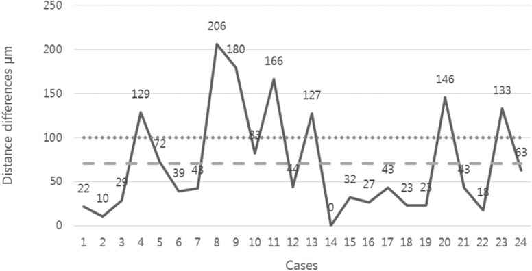
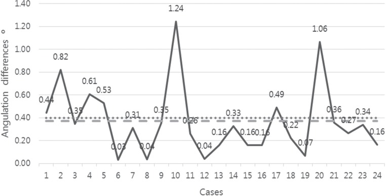
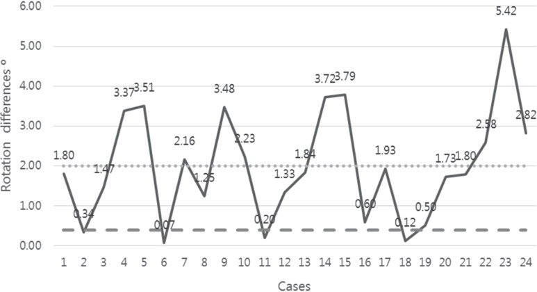
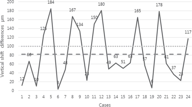
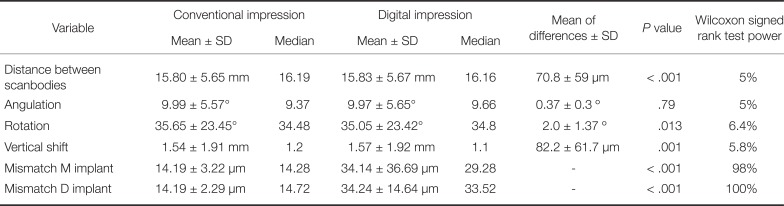
Mean differences between CII and DII groups for distance between the scan bodies were found to be 70.8 ± 59 µm. Mean of differences for angulation was 0.37 ± 0.3°; for the rotation − 2.0 ± 1.37° and for vertical shift − 82.2 ± 61.7 µm. Except for the angulation variable, differences were statistically significant between all digital and conventional impression measurements (Table 1). Surface mismatch measurements comparing DII and CII were 34.14 ± 36.69 µm and 14.19 ± 3.22 µm for the mesial implant scan body and 34.24 ± 14.64 µm and 14.19 ± 2.29 µm for the distal implant scan body. Surface mismatch between mesially and distally located scan bodies in the DII group was significantly different, contrary to the CII group, where no differences were detected.
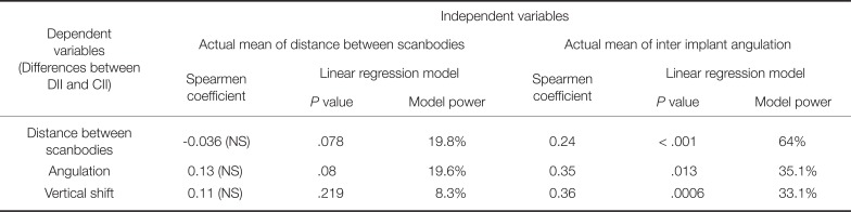
Distance between the scan bodies did not significantly correlate with any measured differences in distance between scan bodies, angulation, or vertical shift according to Spearmen correlation coefficients. Angulation between implants was significantly correlated with detected distance between scan bodies, angulation, and vertical shift differences, but the correlation was weak (Table 2). According to linear regression results, association of inter-implant angulation with measured differences between DII and CII was statistically significant in all variables (P < .05).
DISCUSSION
DII are reported in the literature to be a viable alternative to conventional techniques, but these statements are based mostly on in vitro study results and subjective clinical experience.514 Despite the growing opportunities of new technologies, like replicating mucosal tissue at the formed pontic area and emerging profile of the peri implant tissue15 or recording movements of patient's mandible, a fully digital workflow is not yet possible for every clinical situation. Digital and conventional impression techniques can both be recommended for single-unit fixed dental prostheses. Nevertheless, the digital workflow for short-span implant-supported restorations is less documented. Accurate conventional impressions and bite registrations are still needed for full-arch and complex cases.16
Besides the impression technique, master model fabrication, milling process, type of restoration material, and other factors can influence the final fit of the restoration.16171819 Misfit is regarded as a potential risk factor for both cementand screw-retained restorations. However, no widely accepted clinical threshold of marginal misfit has been determined, and values vary from 10 to 150 µm in the literature.2021 According to Katsoulis et al.,22 there is a biological and mechanical tolerance to the misfit of restorations on implants, and therefore no threshold for maximum gap size or strain levels (screw, framework, implant-bone complex) can be defined. Clinical methods used to assess misfit (visual, tactile, and radiographic) are not sensitive enough to verify a gap of less than 50 µm, and misfit greater than 150 µm can easily be diagnosed without any sophisticated methods. Furthermore, bone strains caused by non-passive implant prosthesis can decrease because of bone adaptation when implants are loaded statically and dynamically.23
Few in vivo studies evaluating the accuracy of digital implant impressions and restorations on implants have been published in the literature.5 The majority of studies are in vitro because it is possible to obtain true reference positions of scan bodies or implants using industrial measuring equipment. Applying industrial-grade reference scanner in clinical study is one of the approaches, but can only be performed in the anterior region of the maxilla under special conditions.24 In this study, all restorations were in the posterior region, so this technique could not be adapted. Another approach was applied in the study by Alsharbaty et al.,9 in which 36 patients with two implant-supported restorations were included. The accuracy of three impression techniques (DII using a Trios IOS, open-tray, and closed-tray CII) was evaluated by comparing them to reference models fabricated from splinted impression copings. Reference models were measured by a coordinate measuring machine. Conventional implant impressions made by the pick-up technique were found to be the most accurate. The accuracy of digital impressions showed the poorest results, and they were rendered clinically unacceptable to fabricate well-fitting restorations on implants. Angular mean deviation was found to be 6.77 ± 0.91°; mean linear displacement was 360 ± 46 µm, and deviation of 3D distance was 220 ± 30 µm. However, this method of obtaining reference data in the clinical study still has to be validated.9
Since there are no reliable techniques to obtain a true reference in the clinical circumstances, master models fabricated from the conventional impressions were used as the best available reference in this study. Also, validation of master model was employed according to strict protocol. Fit assessment of the final restoration also served as additional criteria to confirm the accuracy of conventional impressions. In this way, digital impression accuracy was compared to the conventional one. However, considering general practice, more variability in the accuracy of conventional implant impressions could be expected.
The clinically relevant threshold for the distortions of impressions and restorations is still unknown. Based on the recent study, the threshold for horizontal/vertical misfit and angulation errors of two implant-supported restorations were taken as 100 µm and 0.4°, respectively.10 Statistically significant differences between scan bodies' distances were found between the conventional and digital groups; the resulting mean (70.8 ± 59 µm) was below 100 µm. Vertical shift differences were lower than 100 µm (82.2 ± 61.7 µm), and statistically significant difference was found between CII and DII. Mean angulation differences were below 0.4° (0.37 ± 0.3°). Considering these thresholds, the measured means can be regarded as having minimal clinical relevance. These results are in line with in vitro studies concluding that DII can be as accurate as conventional impressions.1415 Resulting differences were much lower, as in the study by Alsharbaty et al.9 However, considering high standard deviation of the detected differences, maximum values could be of potential clinical significance.
Since rotational misfit of dental implant abutments can affect the fitting of implant superstructures,2526 the rotation of scan bodies was evaluated. Mean rotation difference was found to be 2.0 ± 1.37°, and statistically significant difference was detected between DII and CII. Hence, the abutments without anti-rotational features are commonly recommended for multiple-unit implant-supported restorations. However, in cases in which titanium bases without antirotational features are not available with a certain implant system, minor changes in the rotational position of abutments can negatively influence the fitting of the prosthesis.17
Surface mismatch was more pronounced when the scan bodies were scanned with the IOS than with the laboratory scanner. Differences between Trios3 and D800 were statistically significant for both mesial and distal scan bodies. Surface mismatch when scanned with the IOS was approximately two times higher than in the case of the laboratory scanner. This type of error can lead to discrepancies when the 3D position of the scan body's CAD model is being defined and contributes to the final amount of misfit. The entire workflow can therefore be affected in this way.
Analysis of linear regression models showed that the actual mean of distance between scan bodies did not significantly correlate with distance between scan bodies, angulation, and vertical shift differences detected in both groups. However, angulation between scan bodies significantly (P < .05) affected the differences of all parameters assessed, although Spearmen correlation coefficients were weak, ranging from 0.24 to 0.36. Flügge et al. and Papaspyridakos et al. have reported that increasing angulation and distance between scan bodies negatively affected scanning precision.2728 However, other authors have claimed the opposite.2930 Limited values for inter-implant distance and angulation causing clinically significant errors should be defined for the different IOS in the future.
The accuracy of digital implant impressions can be negatively influenced by additional factors as well: the repositioning accuracy of prosthetic components, construction and shape of the scan bodies, scanning area, scanning sequence, and others.313233 Machining accuracy of prosthetic components34 and different types of implant-abutment connections could have an impact on the results, when the accuracy and precision of the impression techniques are evaluated. The implant system used in the study employs an 11° internal hex connection. Therefore, the results with implants having other types of connections or different geometries of prosthetic components could be different.
Due to constant improvements in digital technologies, the scientific field is rapidly filled with new information validating digital impression procedures. Since the potential of IOS clinical applications is also increasing, further studies will be needed before digital impressions are able to fully substitute conventional ones.
CONCLUSION
Considering limitations, some conclusions can be drawn. Firstly, recorded linear differences between digital and conventional impressions are of limited clinical significance in two implant-supported restorations of up to four units. Secondly, the angulation between implants affected distance between scan bodies, angulation, and vertical shift differences in the scan body position resulting from digital and conventional workflow. Moreover, scan body surface mismatch was higher for the intraoral scanner group. However, methods to obtain true reference data in the clinical studies should be validated and would need further research.
 XML Download