

 PDF
PDF ePub
ePub Citation
 Print
Print


Ayoung Ahn, Jai-Young Koak , Seong-Joo Heo, Seong-Kyun Kim
, Seong-Joo Heo, Seong-Kyun Kim
Abstract
The distance between the natural teeth and the implants is an important factor in preserving the periodontal tissues and esthetics. And abnormal positional displacement and tilting of the teeth during restorative procedure may require intentional root canal treatment and may affect masticatory function. This report is to present a successful full mouth rehabilitation of a patient with uneven dentition and collapsed occlusion using orthodontic and implant treatment. The patient had no symptoms or discomfort of temporomandibular joint disorder such as pain or sound. The orthodontic treatment was continued until implant provisional prosthesis delivery. And the vertical height of occlusion was elevated 2mm on anterior basis for anterior teeth protection and esthetics. After the orthodontic treatment, the implant abutments and natural teeth were finally restored with porcelain-fused-to-metal crowns and bridges. Satisfactory function and esthetic outcomes are observed after 6months of follow up.
Figures and Tables
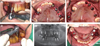
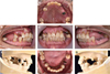 | Fig. 1Intraoral photograph & diagnostic model before treatment. (A) Maxillary, (B) Right, (C) Frontal, (D) Left, (E) Right of the diagnostic model, (F) Mandibular, (G) Left of the diagnostic model.
|
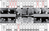 | Fig. 2Tooth examination. (A) Examination chart of maxilla, (B) Intraoral radiographs, (C) Examination chart of mandible.
|
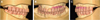
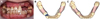 | Fig. 4Orthodontic treatment. (A) Frontal view with clear orthodontic aligner (4th step), (B) 1st RP model, (C) Final RP model.
|
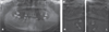
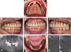
 | Fig. 5Implant installation with surgical guide. (A, D) CT guided implant surgery with surgical guide, (B) After primary surgery of Maxilla, (C, F) After implant 1st surgery, (E) Panoramic radiograph after implant surgery.
|
 | Fig. 7Prosthetic procedure. (A) Custom abutment delivery, (B, C) Abutment level impression (maxillary, mandibular), (D) Metal coping try-in, (E) Porcelain build up and glazing.
|
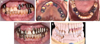
 | Fig. 8Definitive prosthesis. (A) Upper, (B) Right, (C) Frontal, (D) Left, (E) Panoramic photograph after delivery, (F) Lower, (G) TMJ panoramic view after delivery.
|
Table 1
Results of Orthodontic analysis10
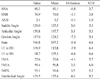
ANB: angle from three points (A point, nasion, B point)
FH: Frankfort horizontal plane (porion - orbitale)
FMA: Frankfort mandibular plane angle
FMIA: Frankfort mandibular incisor plane angle
IMPA: Incisor mandibular plane angle
U1: Maxillary incisor
SN: anterior cranial base
SNA: angle from three points (sella, nasion, A point)
SNB: angle from three points (sella, nasion, B point)
STD: standard deviation.
![]()
References
1. Cao T, Xu L, Shi J, Zhou Y. Combined orthodontic-periodontal treatment in periodontal patients with anteriorly displaced incisors. Am J Orthod Dentofacial Orthop. 2015; 148:805–813.

2. Alfuriji S, Alhazmi N, Alhamlan N, Al-Ehaideb A, Alruwaithi M, Alkatheeri N, Geevarghese A. The effect of orthodontic therapy on periodontal health: a review of the literature. Int J Dent. 2014; 2014:585048.
3. Greene CS, Galang-Boquiren MTS, Bartilotta BY. Orthodontics and the temporomandibular joint: What orthodontic providers need to know. Quintessence Int. 2017; 48:799–808.
4. Willis FM. Features of the face involved in full denture prosthesis. Dental Cosmos. 1935; 77:851–854.
5. Turner KA, Missirlian DM. Restoration of the extremely worn dentition. J Prosthet Dent. 1984; 52:467–474.
6. Dawson PE. Evaluation, diagnosis, and treatment of occlusal problem. Saint Louis: The C. V. Mosby Co.;1974.
7. Schneider D, Schober F, Grohmann P, Hammerle CH, Jung RE. In-vitro evaluation of the tolerance of surgical instruments in templates for computer-assisted guided implantology produced by 3-D printing. Clin Oral Implants Res. 2015; 26:320–325.
8. Ormianer Z, Gross M. A 2-year follow-up of mandibular posture following an increase in occlusal vertical dimension beyond the clinical rest position with fixed restorations. J Oral Rehabil. 1998; 25:877–883.
9. Ormianer Z, Palty A. Altered vertical dimension of occlusion: a comparative retrospective pilot study of tooth- and implant-supported restorations. Int J Oral Maxillofac Implants. 2009; 24:497–501.
10. Korean Association of Orthodontists: Publishing committee of a white paper on malocclusion. Report of measurement results of lateral cephalogram in Korean adults with normal occlusion. Korean Association of Orthodontists;1997.
11. Krishnan V, Davidovitch Z. The effect of drugs on orthodontic tooth movement. Orthod Craniofac Res. 2006; 9:163–171.
12. Jiang Q, Li J, Mei L, Du J, Levrini L, Abbate GM, Li H. Periodontal health during orthodontic treatment with clear aligners and fixed appliances: A meta-analysis. J Am Dent Assoc. 2018; 149:712–720.e12.
13. Dawson PE. Functional occlusion from TMJ to smile design. Mosby Elsevier;2007.
14. Gopi Chander N, Venkat R. An appraisal on increasing the occlusal vertical dimension in full occlusal rehabilitation and its outcome. J Indian Prosthodont Soc. 2011; 11:77–81.
15. Abduo J, Lyons K. Clinical considerations for increasing occlusal vertical dimension: a review. Aust Dent J. 2012; 57:2–10.
16. Marcotte GR, West DW, Baar K. The molecular basis for load-induced skeletal muscle hypertrophy. Calcif Tissue Int. 2015; 96:196–210.
 XML Download