

 PDF
PDF ePub
ePub Citation
 Print
Print


INTRODUCTION
General Considerations
Appropriate Criteria
Patient Preparation
1) In cases of difficulty with breath holding, arrhythmia, or motion artifacts, consider a single-shot module or free breathing with real-time image acquisition.
2) In cases of difficulties due to profound respiratory motion, consider an abdominal band to reduce artifacts.
3) In cases of difficulties due to pericardial effusion and a weak ECG signal, consider peripheral pulse gating.
4) In cases of difficulties due to ghost artifacts caused by pleural effusion and respiratory difficulties, consider postponing the CMR imaging until after pleural effusion drainage.
Sequence Terminology
-
I. MR sequences at a glance
-
1. Spin-echo
-
2. Gradient-echo (GRE)
-
3. Preparation pulses
-
A. Inversion pulses
1) Invert the longitudinal magnetization (Fig. 5A)
2) After an inversion pulse, longitudinal magnetization starts to recover toward the equilibrium from the inverted point crossing the nulling point
3) Can be used to null the signal of selective objects, such as water, fat, blood, or the myocardium
-
B. Saturation pulses
1) Saturate the longitudinal magnetization to null a net magnetization (Fig. 5B)
2) After a saturation pulse, longitudinal magnetization starts to recover toward the equilibrium
-
-
4. Echo-planar imaging (EPI)
-
-
II. Cardiac MRI sequences (Table 1)
1. Spin echo: morphology, anatomy, tumor, etc.
-
2. Gradient echo: cine, perfusion, late gadolinium enhancement (LGE), MR coronary angiography (MRCA)
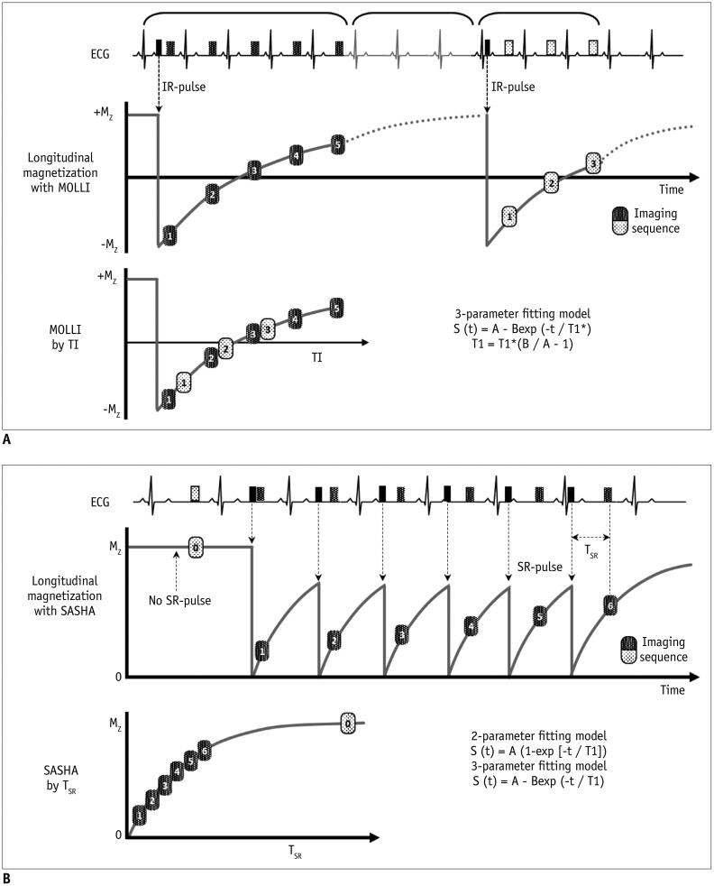
3. Inversion recovery: LGE, T1 mapping (Modified look-locker inversion recovery, MOLLI)
4. Saturation pulse: first-pass perfusion, fat saturation pulses, T1 mapping (Saturation recovery single-shot acquisition, SASHA)
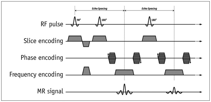
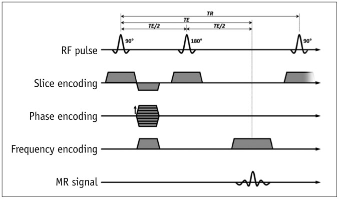
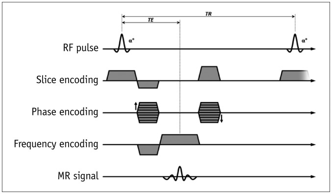
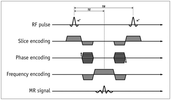
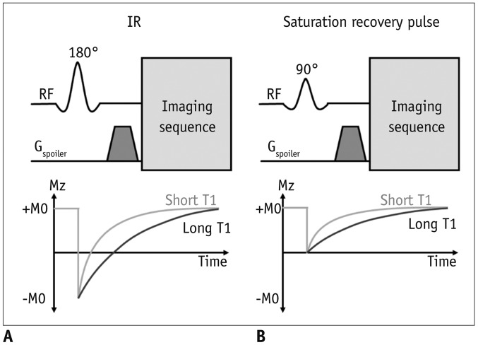
Table 1
Routine Cardiac MRI Sequence Terminology (Vendor)
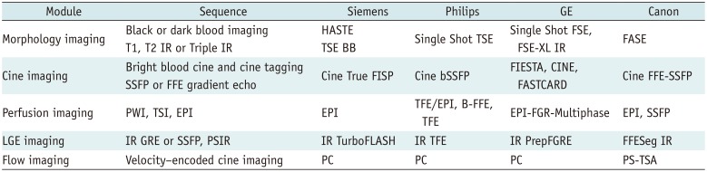
BB = black blood, bSSFP = balanced steady-state free precession, EPI = echo planar imaging, FASE = single-shot turbo spin echo, FFE-SSFP = fast field echo-steady state free precession, FGR = fast gradient recalled acquisition, FGRE = fast gradient echo, FIESTA = fast imaging employing steady-state acquisition, FISP = fast imaging with steady state precession, FLASH = fast low angle shot, FSE = fast spin echo, FSE-XL = fast spin echo-accelerated, GRE = gradient echo, HASTE = half-Fourier acquisition single-shot turbo spin-echo, IR = inversion recovery, LGE = late gadolinium enhancement, PC = phase contrast, PS = phase shift, PSIR = phase-sensitive inversion-recovery, PWI = perfusion weighted image, TSA = time-shift analysis, TSE = turbo spin echo, TSI = time-signal intensity
![]()
Imaging Plane
Basic Planes
-
I. Left ventricle (LV) 2-chamber view, LV 4-chamber view, LV short axis view
-
1. Scout imaging or localizer imaging
-
2. Vertical long axis image (Supplementary Fig. 1)
-
3. Horizontal long axis (Supplementary Fig. 2)
-
4. Short axis image (Supplementary Fig. 3)
-
5. Four-chamber view (Supplementary Fig. 4)
-
6. Two-chamber view (Supplementary Fig. 5)
-
-
II. LV 3-chamber view and LV outflow tract (LVOT) long axis
-
1. LV 3-chamber view (Supplementary Fig. 6)
-
2. LVOT long axis view (Supplementary Fig. 7)
-
-
III. RV
-
1. RV short axis (Supplementary Fig. 8)
-
2. Right ventricle outflow tract (RVOT) view (Supplementary Fig. 9)
-
Specific Planes
-
I. MV view (Supplementary Fig. 10)
-
II. TV (Supplementary Fig. 11)
-
III. Aortic valve (AV) view (Supplementary Fig. 12)
-
IV. Pulmonic valve (PV) view
-
V. MPA view (Supplementary Fig. 13)
-
VI. Right pulmonary artery (RPA) and left pulmonary artery (LPA) views (Supplementary Fig. 14)
Special Considerations and Patient Safety
Field Strength Considerations
-
I. The popularity of 3T CMR
-
II. Safety
-
III. RF exposure
-
IV. CMR at 3T influences the performance of several sequences
CMR at 3T requires protocol optimization, careful shimming, and adjustment of the RF pulses to prevent artifacts
1. Improvements: first-pass perfusion, MR angiography, coronary imaging, myocardial tagging, MR spectroscopy, and fat saturation
2. Equivalent to 1.5T: LGE, flow quantification, and black-blood imaging
3. Considerable limitation: SSFP
4. Main challenges: B0 inhomogeneities, B1 inhomogeneities, off-resonance band artifacts, susceptibility effects, and chemical shift artifacts
Devices
-
I. CIED in MRI machines
1. Common clinical situation
2. Historically regarded as a contraindication but no longer an absolute contraindication to MRI
-
3. Adverse interactions
A. Device failure, lead failure, heating, force, torque
B. Magnetic susceptibility artifacts (Fig. 6)
-
4. MR-conditional CIED
A. CMR is possible under the adequate workflow protocol
B. Consider the device, device insertion duration, scan region, battery power, MR system, and sequences
C. Need cooperation between cardiologists and radiologists
-
D. MR safety information on the websites
1) Medtronic: https://www.medtronic.com/us-en/healthcare-professionals/mri-resources.html
2) Boston Scientific: http://www.bostonscientific.com/en-US/customer-service/mri-information.html
3) MRI safety.com: http://www.mrisafety.com
-
5. MR-non-conditional CIED
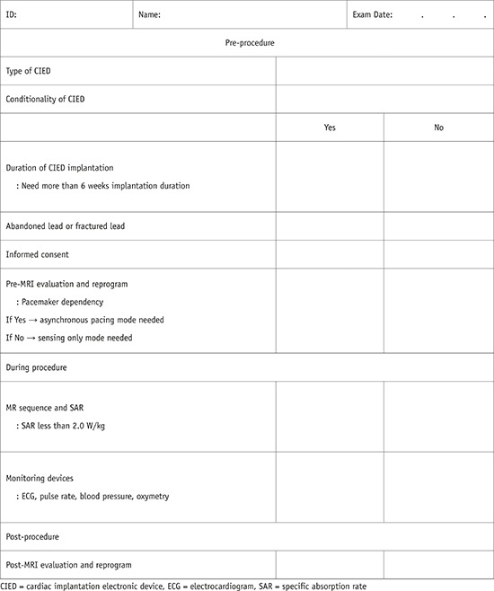
6. MR-conditional CIED checklists are provided in Appendix 2
-
7. Recommendations to minimize artifacts from a CIED
A. Sufficient distance (> 6 cm) between the CIED pulse generator and the heart or CIED pulse generator in the right chest wall
B. Spoiled GRE sequence with wide bandwidth rather than SSFP
C. Change the center offset frequency using the SSFP sequence
D. Long-axis plane for the mid to apical LV and shortaxis plane for the LV base
Drugs
-
I. Gadolinium-based MRI contrast agents
1. Shorten the relaxation times of nuclei within the body
-
2. Nephrogenic systemic fibrosis
-
3. Brain deposition
4. The Korean Food and Drug Administration recommends the use of a gadolinium-based MRI contrast agent with a macrocyclic structure. In Korea, the supply of gadopentetate, gadodiamide, and gadoversetamide has been discontinued. In the EU, the use of gadolinium-based MRI contrast agents with a linear structure is prohibited
-
II. Pharmacologic stressors and vasodilators
-
1. Dobutamine
-
A. Inotrope
-
B. Contraindications
1) Unstable angina pectoris
2) Severe systemic arterial hypertension (≥ 220/120 mm Hg)
3) Severe aortic stenosis
4) Obstructive hypertrophic cardiomyopathy with hemodynamic significance
5) Uncontrolled cardiac arrhythmias
6) Uncontrolled congestive heart failure
7) Endocarditis
8) Myocarditis or pericarditis
9) Family history of sudden cardiac death
10) Aortic dissection
11) High-grade aortic aneurysm
12) Mobile thrombus in LV or left atrium
-
-
2. Adenosine, dipyridamole, and regadenoson
-
A. Vasodilators
-
B. Adenosine
1) Acts on the vascular smooth muscle surface to cause vasodilation
-
2) Binds non-selectively to A1, A2A, A2B, and A3
3) Dose: 0.14 mg/kg/min
4) Half-life: 10–30 seconds
-
5) Competitive inhibitors of adenosine
-
6) Contraindications
a) Hypersensitivity to adenosine
b) Bronchoconstriction or bronchospastic disease
c) 2nd or 3rd degree atrioventricular block
d) Significant sinus bradycardia (resting heart rate < 45 bpm)
e) Systolic blood pressure less than 90 mm Hg
f) Severe arterial hypertension
g) Myocardial infarction within 3 days
h) Disease requiring the regular use of inhalers for asthma, sinus arrhythmia, stenotic valvular disease, or carotid artery stenosis
7) Antidote: intravenous (IV) aminophylline
-
C. Dipyridamole
-
D. Regadenoson
-
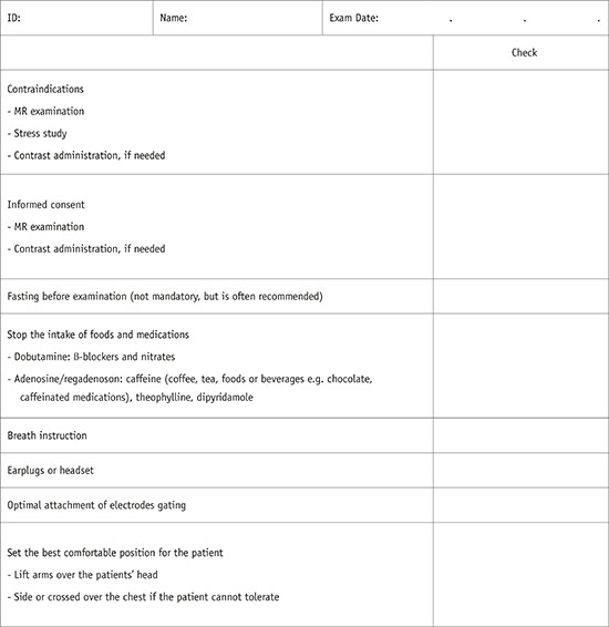
3. Please use checklists to ensure patient safety and image quality (2).
-
Exam Modules
Cine Imaging
I. Purpose: to assess cardiac wall motion
-
II. Sequences
-
III. Image parameters
-
IV. Tips
-
1. Uses retrospective gating rather than prospective triggering
-
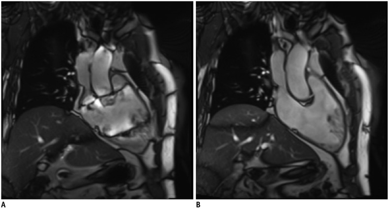
2. Banding artifacts (Fig. 7)
-
-
V. Dobutamine stress test
1. To evaluate the viability and contractile reserve
2. Avoid beta-blockers and nitrates
-
3. Infusion dose
-
4. Caution: indications for stopping the test
A. New wall motion abnormality or wall thickening abnormality
B. Systolic blood pressure > 240 mm Hg or diastolic blood pressure > 120 mm Hg
C. Systolic blood pressure decrease of 20 mm Hg or greater below baseline
D. Severe chest pain or other intractable symptoms
E. Complex cardiac arrhythmias or reaching peak heart rate
Perfusion Imaging
I. Purpose: to evaluate myocardial perfusion (ischemia)
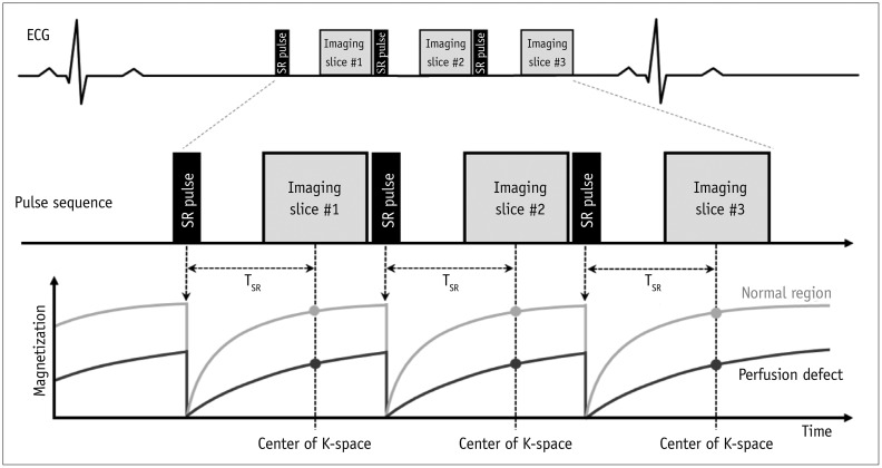
II. Sequences: saturation-recovery imaging with GRE-EPI hybrid, GRE, or SSFP readout (Fig. 8)
-
III. Image parameters
-
IV. Scan protocol
1. Scout imaging: same as LV structure and function
-
2. Stress myocardial perfusion
-
A. Slices: at least three short-axis slices per heartbeat at the LV base, mid, and apical levels
-
B. Do a rehearsal scan without contrast or vasodilator injection (dry run) to check the image quality and correct the parameters
-
C. Vasodilator infusion: adenosine stress perfusion
-
D. Gadolinium contrast agent
E. Breath-hold: during the early phases of contrast infusion, before contrast reaches the LV cavity
F. Readout for 40–60 heartbeats, in which time contrast will have passed through the LV myocardium
-
3. LV function mode between a stress test and resting test while waiting for contrast washout
-
4. Rest myocardial perfusion imaging
5. LGE
-
V. Tips
LGE Imaging
I. Purpose: to evaluate myocardial viability
-
II. Sequences (Fig. 10)
-
III. Image parameters
-
IV. Scan protocol
-
V. Tips
1. I f the inversion time is inaccurate, use the PSIR sequences
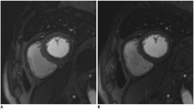
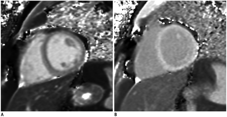
2. If the image quality is poor due to motion artifacts or poor breath holding, use single shot LGE (Fig. 11)
-
3. Ghosting artifacts with long T1 tissue
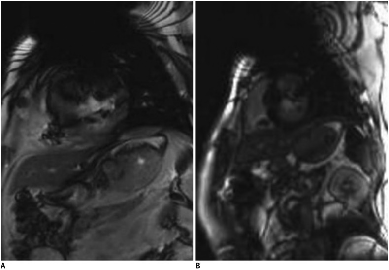
Fig. 11
Better image quality of single shot LGE in patient with poor breath holding.
LGE image with two-dimensional segmented inversion recovery gradient-echo (A) in patient with poor breath holding shows poor image quality with significant motion artifact. Single shot LGE (B) shows much improved image quality with less motion artifact.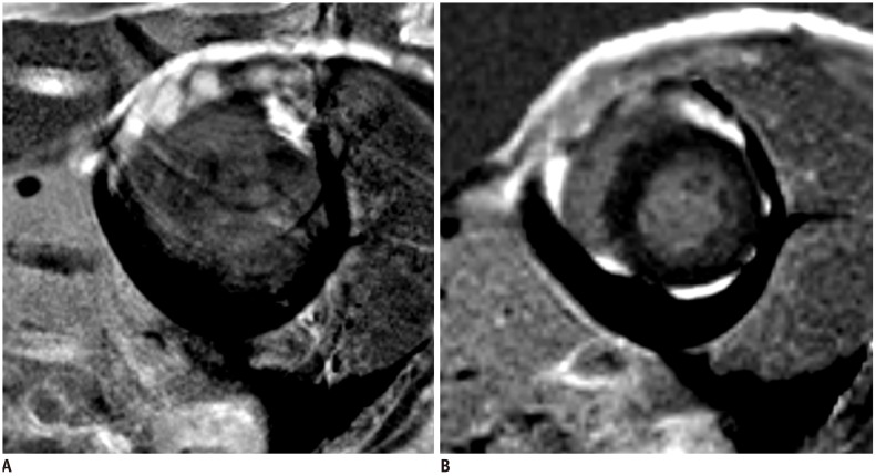

Flow Imaging
-
I. Purpose: to measure flow velocity and volume
-
II. Sequences
-
III. Image parameters
1. ECG gating: retrospective gating includes the entire diastolic portion of the cardiac cycle
2. Slice thickness: 5–8 mm
3. In-plane resolution: at least 1/10 of the vessel diameter, 1.3–2.0 mm
4. Velocity encoding sensitivity (VENC): adapted to the expected velocities
5. Acquired time frames: 25–30 frames/R-R interval
6. Average number of signals: 2–3
-
IV. Tips
-
1. Plane: perpendicular to the vessel and distal to valve leaflet tips of interest
-
2. VENC (Fig. 12)
3. TE: as short as possible
-
4. Spatial resolution
-
5. Temporal resolution
Fig. 12
VENC effect on phase-contrast flow imaging.
Very low VENC factor (A, VENC factor = 90 cm/s) causes aliasing on phase contrast flow image of ascending aorta. Usual peak of ascending aorta is 100–160 cm/s (B, VENC factor = 130 cm/s; C, VENC factor = 160 cm/s). Very high VENC factor (D, VENC factor = 190 cm/s) causes noise and inaccurate measurement. VENC = velocity encoding sensitivity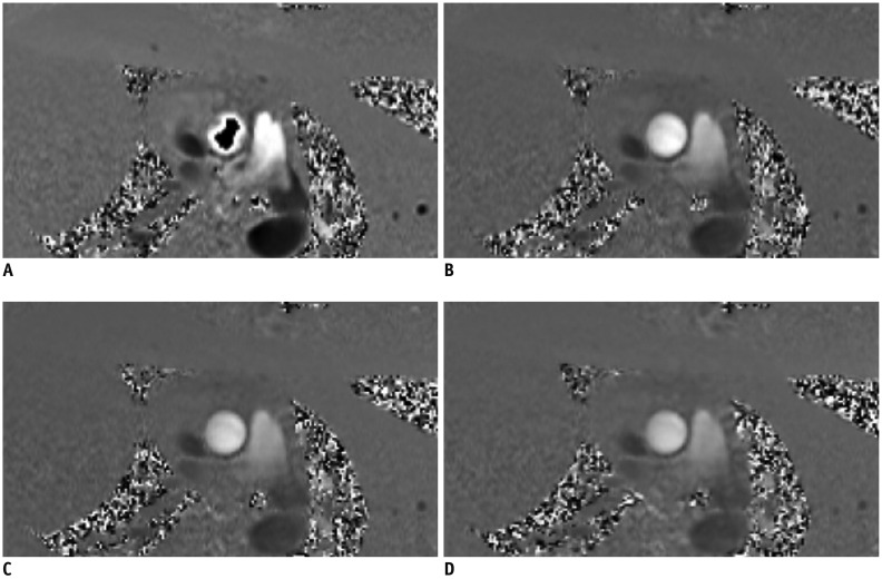
-
Morphology Imaging
I. Purpose: to delineate anatomic structures
-
II. Sequences
-
III. Image parameters
-
IV. Tips
1. Breath-hold, pre-contrast segmented FSE or TSE imaging with double inversion recovery: sequence with good CNR preferred
2. If motion artifact is significant with FSE or TSE, try HASTE or dark blood GRE
-
3. Optimizing readout time by acquiring multiple images throughout the diastole is essential to minimizing dropout artifacts
Tissue Characterization: T1 Mapping
I. Purpose: to evaluate the absolute T1 value of the myocardium
-
II. Sequences (Fig. 13)
-
III. Image parameters
-
IV. Tips
-
V. Scan protocol (Fig. 14)
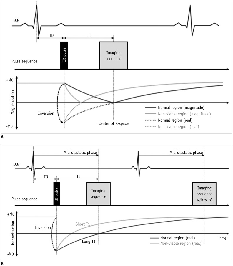
Fig. 13
T1 mapping sequences.
![]()
Fig. 14
Native T1 map and post T1 map.
![]()
Tissue Characterization: T2 Mapping
Coronary Angiography
Disease/Symptom-Based Protocol
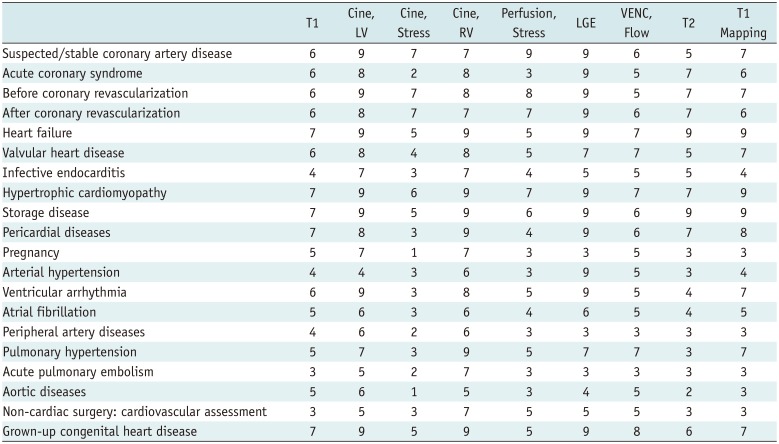
Table 2
Disease/Symptom-Based Protocol, Based on Questionnaire
![]()
 XML Download