

 PDF
PDF ePub
ePub Citation
 Print
Print


INTRODUCTION
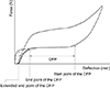
Nickel-titanium (NiTi) materials can exert a consistent force regardless of the amount of deflection within the range of the deactivation force plateau (DFP).12345 Due to this characteristic, NiTi closed-coil springs (NiTi-CCSs) have been applied to extraction space closure, individual tooth movement (retraction or protraction), or forced eruption of an impacted tooth.67 However, as the deflection of the springs reaches the end of the DFP, the force level decreases rapidly (Figure 1). Once the springs can no longer maintain an adequate force, they must either be replaced with another set of short-length springs or they must be reactivated to accomplish complete tooth movement.8 In this respect, it would be advantageous for clinical use if the DFP of NiTi-CCSs could be extended to the end of the deactivation curve (Figure 1).
Wichelhaus et al.1 compared the mechanical characteristics of 24 commercially available NiTi-CCSs and classified them into preactivated and un-preactivated groups, where the term “preactivation” refers to the torsional bias stress applied to the springs by manufacturers during the manufacturing process.1 In that study, the preactivated group consisted of springs in which the DFPs extended until the springs were almost fully deactivated, while the un-preactivated group included springs in which the DFPs ended 3 to 5 mm before the springs were fully deactivated.1 Upon evaluation, the preactivated springs had a distinct advantage over unpreactivated springs in that they could maintain a consistent force for even small deformations, thus allowing tooth movement to be completed without requiring reactivation of the springs.1 Although clinicians can also activate NiTi-CCSs by straining them before use, this has been reported to have no clinically significant effect on the force generated by NiTi-CCSs.2910
Since NiTi materials exhibit nonlinear force-deflection characteristics, previous studies11112 have suggested methods for calculating the range of the force plateau (FP) using the ratio between the maximum and minimum slopes of the force-deflection curve. However, as such methods are based on the relative ratio of slopes within a single NiTi material, it is desirable to develop an objective method based on mathematical calculations for determining the range of the FP.
Recently, a method of changing (reversing) the coiling direction of NiTi coil springs has been introduced in the field of engineering.1314 This method is reported to provide an initial tension to the springs and extend the end point of the DFP to almost the end of the deactivation curve.1314 It would be advantageous in clinical use if the end point of the DFP of orthodontic NiTi-CCS could be extended to the origin point by applying this method.1 Therefore, the purpose of this study was to investigate the effects of reversing the coiling direction in conventional NiTi-CCSs on the force-deflection characteristics. The null hypothesis of this study was that reversing the coiling direction of NiTi-CCSs would not produce significant changes in the force-deflection characteristics including the FP range, force level, and amount of mechanical hysteresis.
MATERIALS AND METHODS
Two commercially available conventional NiTi-CCS groups (Ormco NiTi extension spring light force [Ormco Co., Glendora, CA, USA] and GAC coil springs light [GAC International Inc., Bohemia, NY, USA]), each of which had an approximate 100 g of force, a total length of 8.5 to 9.0 mm, and a coil length of 3.2 to 3.5 mm, were used as control groups. According Wichelhaus et al.,1 Ormco NiTi-CCSs exhibit the force-deflection characteristics of un-preactivated springs while GAC NiTi-CCSs exhibit those of preactivated springs.
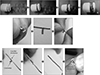
To investigate the effects of reversing the coiling direction on the force-deflection characteristics, experimental groups were directly made from the control groups by a method illustrated in Figure 2A. Although there was some risk that reversing the coiling direction of springs would result in permanent plastic deformation, the probability of this was considered to be very low for the following reasons.14 First, the reverse coiling procedure was performed at room temperature (about 20℃), which is below the austenite finishing temperature of the NiTi alloy.15 Thus, the NiTi alloys of the coil springs were in the transition phase from martensite to austenite, thereby preventing permanent plastic deformation while not allowing the coil to return to its original shape. Second, this procedure was designed to simply change the order of coil element, thus introduce minimal stress by only applying 0.16 mm of deformation which is the diameter of the NiTi wire of coil elements.
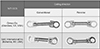
Here, the respective groups of commercially available conventional NiTi-CCSs are referred to as control groups and those of the reverse-wound NiTi-CCSs as experimental groups. In the experiments, the results of the Ormco-Conventional group were compared to those of the Ormco-Reverse group, while those of the GAC-Conventional group were compared to those of the GAC-Reverse group. Each group contained 20 springs (Table 1 and Figure 3).
A power analysis was performed using a sample size determination program (version 2.0.1 [Registration no. 2007-01-122-004453]; Seoul National University Dental Hospital, Seoul, Korea) to determine the sample size based on the means and standard deviations derived from a previous study.16
To investigate the force-deflection characteristics in the control and experimental groups, the tensile tests were performed using a MTS tensile tester (MTS Insight; MTS Systems Corporation, Eden Prairie, MN, USA) equipped with a 25 N static load cell. To eliminate the mechanical play between the eyelet of the NiTi-CCS and the fixture connected to the tensile tester, each specimen was preloaded to a force level of 0.1 ± 0.01 N.16 Then, the specimens were activated to a 14 mm displacement and deactivated to the initial pre-loaded displacement at a rate of 20 mm/minutes in a temperature-controlled acrylic chamber (37 ± 1℃).
The rationale for stretching the springs to 14 mm was as follows. First, in clinical situations, NiTi-CCSs are typically connected from the hook on the first molar tube to the hook on the canine bracket when retracting the canine into the extraction space, and the distance between these hooks is approximately 23 mm.17 Because the total length of each NiTi-CCS used in this study was about 8.5 to 9.0 mm, a 14 mm extension was deemed appropriate for simulating an actual clinical situation. Second, this extension was chosen because most NiTi-CCSs exhibit superelasticity when activated to a distance more than four times the length of the coil portion (13.2 mm for Groups 1 and 3; 12.8 mm for Groups 2 and 4).16
After the data on force and displacement were acquired at every interval of 0.04 mm displacement using the Testworks 4 program (MTS Systems Corporation), force-deflection curves for each specimen were plotted.
The variables used in this study are described in Figure 4. The FP was defined as the region in which the slope of the curve was less than 0.1 N/mm. This definition is based on the study of Wichelhaus et al.,1 which reported that the slopes of the FPs of NiTi-CCSs with strong superelasticity were between 0.01 and 0.09 N/mm. The slope of the deactivation curve was calculated using the derivative of each curve at every tested displacement using MATLAB R12 software (The MathWorks Inc., Natick, MA, USA). The range of the DFP (including the start and end points), the force levels on the activation and deactivation curves, and the amount of mechanical hysteresis were all measured.
Statistical analyses were performed to compare the force-deflection characteristics between the conventional and reverse wound NiTi-CCSs in the same batch. After performing normality assessments via the Shapiro-Wilk tests, Mann-Whitney U tests were performed. All statistical analyses were performed using the SPSS program (version 22.0; IBM Corp., Armonk, NY, USA). The level of significance for all tests was p < 0.05.
RESULTS
Although all groups exhibited typical patterns of the force-deflection curves of NiTi materials, the force-deflection characteristics of the two control groups changed significantly when the coiling direction was reversed. In addition, two control groups exhibited different patterns of changes in the force-deflection characteristics when the coiling direction was reversed.
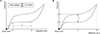
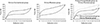
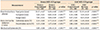
Compared to the Ormco-Conventional group, the start and end points of the DFP for the Ormco-Reverse group shifted toward the origin point (i.e., the end point of the deactivation curve) (from 10.2 to 6.3 mm and from 2.3 to 0.6 mm, respectively), the range of the DFP decreased (from 7.9 to 5.6 mm), the activation and deactivation force levels increased (from 2.1 to 2.8 N; from 1.2 to 1.3 N, respectively), and the amount of mechanical hysteresis increased (from 1.0 to 1.5 N) (all p < 0.001; Figure 5 and Table 2).
Compared to the GAC-Conventional group, the start and end points of the DFP for the GAC-Reverse group shifted away from the origin point (from 9.6 to 11.5 mm; from 0.2 to 3.3 mm, respectively), the range of the DFP decreased (from 9.5 to 8.2 mm), the activation and deactivation force levels decreased (from 1.7 to 1.4 N; from 1.1 to 0.9 N, respectively), and the amount of mechanical hysteresis decreased (from 0.6 to 0.4 N) (all p < 0.001; Figure 6 and Table 2).
Although the observed changes in the deactivation force level may be clinically insignificant, the corresponding pattern was opposite between the two groups (Δ0.1 N increase in the Ormco-Reverse group compared to the Ormco-Conventional group; Δ0.2 N decrease in the GAC-Reverse group compared to the GAC-Conventional group; Figures 5, 6, and Table 2). The direction of the shift of the end point of the DFP in relation to the origin point was also opposite in the two groups (2.3 mm in the Ormco-Conventional group to 0.6 mm in the Ormco-Reverse group; 0.2 mm in the GAC-Conventional group to 3.3 mm in the GAC-Reverse group; Figures 5, 6, and Table 2).
DISCUSSION
The mechanical properties of NiTi-CCSs are affected by two major factors including the fabrication (composition of the alloy, diameters of wire and lumen, pitch angle, length of springs) and the oral environments (temperature change and mechanical deformation).12910 In the present study, by comparing the mechanical properties of conventional and reverse-wound NiTi-CCSs, we found that the coiling direction may be another factor that significantly affects the force-deflection characteristics of NiTi-CCSs.
The force-deflection characteristics of the two conventional NiTi-CCS groups were not significantly different from those of previous studies.16716181920 The force levels of the DFPs of the Ormco- and GAC-Conventional groups were 1.2 and 1.1 N, respectively (Table 2), which are almost the same as the results of Vieira et al.16 (1.1 N for Ormco light NiTi-CCS; 1.0 N for GAC light NiTi-CCS). The ranges of the DFPs for the Ormco- and GAC-Conventional groups were 7.9 mm (10.2 mm to 2.3 mm) and 9.5 mm (9.6 to 0.2 mm), respectively (Table 2), which are similar to those obtained by Wichelhaus et al.1 (Ormco: 7.9 mm [11.4 to 3.5 mm]; GAC: 10.2 mm [10.8 to 0.6 mm]). Some of the noted differences in the start and end points of the DFPs seem to have arisen from differences in the methods used to calculate the FP range.
In our testing, the change in the coiling direction resulted in significant changes in the force-deflection characteristics in the conventional NiTi-CCSs. In the Ormco-Reverse group, the entire DFP shifted toward the origin point compared to that in the Ormco-Conventional group. The shift in the end point of the DFP in the Ormco-Reverse group (from 2.3 to 0.6 mm) may allow a consistent force to be maintained until the springs are almost fully deactivated. However, the shift in the start point of the DFP in the Ormco-Reverse group (from 10.2 to 6.3 mm) may result in the application of a relatively high and rapidly decreasing force in the initial stage of spring application. This indicates the NiTi-CCSs in the Ormco-Reverse group would not be appropriate to be used in the initial stage of tooth movement when there is a large deformation of the spring; however, they may be useful when a constant force is required with only a small deformation of the spring (e.g., intrusion of the teeth).
On the other hand, in the GAC-Reverse group, the entire DFP shifted away from the origin point compared to the GAC-Conventional group. The shift in the start point of the DFP in the GAC-Reverse group (from 9.6 to 11.5 mm) may enable the springs to apply a constant force earlier in the initial stage of tooth movement. However, the shift in the end point of the DFP in the GAC-Reverse group (from 0.2 to 3.3 mm) might hinder the maintenance of constant force as tooth movement progresses and the deflection of the spring reaches the end point of the DFP.
According to the study of Wichelhaus et al.,1 the GAC-Conventional and Ormco-Reverse groups exhibited the force-deflection characteristics of preactivated springs, while the Ormco-Conventional and GAC-Reverse groups exhibited those of un-preactivated springs (Figures 5 and 6). This suggests that as a result of the reversing procedure, the force-deflection characteristics of the unpreactivated springs changed to those of preactivated springs (from the Ormco-Conventional group to the Ormco-Reverse group, Figure 5) and vice versa (from the GAC-Conventional group to the GAC-Reverse group, Figure 6). In this respect, the application of the reversing procedure in the Ormco-Conventional group may provide a torsional component to the wire,1 which may produce the effect of preactivation in the springs. On the other hand, the same procedure in the GAC-Conventional group might eliminate the torsional component of the wire,1 thereby negating the preactivation introduced during the manufacturing process.
In NiTi-CCSs, further compression is impossible beyond their original state. However, by changing the coiling direction, NiTi-CCSs can be compressed further beyond their original state, which can provide an initial tension to the springs. The mechanisms of these changes can be stated as follows. First, an initial tension can increase the amount of force required to extend the springs.14 Second, this initial tension causes an immediate increase in force right after the start of the activation curve. Third, because this initial tension is maintained until the end of the deactivation curve, a consistent force can be applied until the springs are almost fully deactivated. The changes in the force-deflection curve from the Ormco-Conventional group to the Ormco-Reverse group (Figure 5) suggest that the springs can be compressed and the initial tension can be provided by the reversing procedure. This initial tension could act as a biased torsional stress,1 which would preactivate the springs. The observed increase in the force level in the Ormco-Reverse group compared to the Ormco-Conventional group (Figure 5) may be a result of the initial tension.
In contrast, the changes in the force-deflection curve from the GAC-Conventional group to the GAC-Reverse group (Figure 6) suggest that the GAC NiTi-CCSs were already in the compressed state and the reversing procedure served to decompress the springs, thus eliminating the initial tension. These changes also indicate that reversing preactivated springs may eliminate the biased torsional stress1 and thereby act to eliminate the effects of preactivation. The observed decrease in the force level in the GAC-Reverse group compared to the GAC-Conventional group (Figure 6) may be a result of eliminating the initial tension.
The mechanical hysteresis of the NiTi-CCSs also changed by reversing the coiling direction. After applying the reversing procedure, the amount of mechanical hysteresis increased significantly in the Ormco-Reverse group compared to the Ormco-Conventional group (Δ0.6 N), while it decreased in the GAC-Reverse group compared to the GAC-Conventional group (Δ0.2 N) (Figures 5, 6, and Table 2). These changes also suggest that the Ormco and GAC NiTi-CCSs had undergone different manufacturing process in terms of applying bias stress to the springs.
Since reversing the coiling direction of the NiTi-CCSs evaluated in this study affected the force-deflection characteristics, future studies should include other commercially available NiTi-CCSs to more fully elucidate the associated mechanism. In addition, while manufacturers do not normally state whether their NiTi-CCSs are preactivated or un-preactivated, this research would benefit from a clear understanding of the coiling direction and any applied preactivation. In addition, the effects of temperature changes and repeated mechanical stresses on the mechanical properties of reverse-wound NiTi-CCSs should be investigated in detail as these occur frequently in the oral cavity. Finally, further studies are needed to determine the likelihood of permanent deformation of NiTi-CCSs during reverse coiling. This can be assessed by measuring the changes in the coil diameter near the end of the CCS or by using differential scanning calorimetry.
CONCLUSION
• The null hypothesis that reversing the coiling direction of NiTi-CCS would not produce significant changes in the force-deflection characteristics, including the FP range, force level, and amount of mechanical hysteresis, was rejected.
• Two commercially available NiTi-CCS groups exhibited different patterns of changes in the force-deflection characteristics when the coiling direction was reversed.


 XML Download