Abstract
PURPOSE
While dental implants have displayed high success rates, poor mechanical fixation is a common complication, and their biomechanical response to occlusal loading remains poorly understood. This study aimed to develop and validate a computational model of a natural first premolar and a dental implant with matching crown morphology, and quantify their mechanical response to loading at the occlusal surface.
MATERIALS AND METHODS
A finite-element model of the stomatognathic system comprising the mandible, first premolar and periodontal ligament (PDL) was developed based on a natural human tooth, and a model of a dental implant of identical occlusal geometry was also created. Occlusal loading was simulated using point forces applied at seven landmarks on each crown. Model predictions were validated using strain gauge measurements acquired during loading of matched physical models of the tooth and implant assemblies.
RESULTS
For the natural tooth, the maximum vonMises stress (6.4 MPa) and maximal principal strains at the mandible (1.8 mε, −1.7 mε) were lower than those observed at the prosthetic tooth (12.5 MPa, 3.2 mε, and −4.4 mε, respectively). As occlusal load was applied more bucally relative to the tooth central axis, stress and strain magnitudes increased.
CONCLUSION
Occlusal loading of the natural tooth results in lower stress-strain magnitudes in the underlying alveolar bone than those associated with a dental implant of matched occlusal anatomy. The PDL may function to mitigate axial and bending stress intensities resulting from off-centered occlusal loads. The findings may be useful in dental implant design, restoration material selection, and surgical planning.
Dental implants have demonstrated a survival rate of 94.6% over the last ten years;1 however, short- and long-term complications occur in 10 – 20% of the cases.234 Most failures of dental implants are attributed to a range of biological and mechanical factors that influence implant osseointegration, such as periimplant infection and bone overloading, which can lead to component loosening and fracture of the underlying bone.4567 A number of studies have assessed mechanisms of load transfer from the occlusal surface to bone, as it is thought that the resultant biological response of bone within the vicinity of the implant may ultimately influence bone remodelling, implant osseointegration and prosthesis longevity.8910 At present, however, the stress and strain response of dental implants under normal occlusal loading conditions is not well understood, as they cannot be measured in vivo.
Finite element models have been widely used to estimate the influence of implant positioning, stress thresholds that initiate or inhibit alveolar bone resorption, and the impact of tangential loading on bone stress response.111213 Compared to natural bone-periodontal ligament (PDL)-tooth complexes, implant-bone complexes have demonstrated greater mobility and yield at lower alveolar bone strains;1415 however, the way in which load is transferred from different regions on the occlusal surface to the alveolar bone in these cases has not been quantified to date.16 Bone stress and strain levels at the dental implant-bone interface are clinically relevant, since low loading of the alveolar bone socket and adjacent bone have the potential to result in bone resorption and ultimately implant loosening, while excessively high strains may lead to bone loss and microfracture.171819
The biomechanical response of the bone-implant complex, including mechanical strain, is influenced by a number of factors including bone-implant contact behaviour and the location of the load on the occlusal surface. The aims of this study were twofold. Firstly, to develop and validate a three-dimensional (3D) model of a natural mandibular first premolar and a dental implant of identical crown morphology; and secondly, to use this model to quantify the responses of the tooth, implant and associated dental structures and underlying bone to loading through a range of positions on the occlusal surface.
An intact right side first mandibular premolar of a healthy adult (age 23 years) was extracted prior to orthodontic treatment. The tooth was cleaned and soaked in saline solution. The severed periodontal ligament was removed, and the tooth was stored at room temperature until testing. A prevulcanized natural rubber latex film (Blatex-500; Barnes Products, Sydney, Australia) was brushed onto the tooth root with a thickness of approximately 0.2 mm to represent the geometry of the PDL. The tooth was embedded in a polymethyl methacrylate (PMMA) model representing the right quadrant of the mandible. A single-crown dental implant set (4 mm diameter and 13 mm length) comprising a titanium implant (External Hex Brånemark, Mk III TiUnite, Nobel Biocare AB, Göteborg, Sweden), abutment, abutment screw, and a premolar crown made of monolithic zirconia was implanted into an identical PMMA model of the mandible in the same position as the natural tooth. Ethical approval was obtained through the University of Melbourne human ethics advisory group, and written informed consent provided (Ethics ID: 1442212.1).
Using a previously described method,20 two tri-axial strain gauge rosettes (N32-FA-1-120-11-VS3, Showa, Tokyo, Japan) were attached to the natural and implant tooth assembly, with one rosette placed on both the buccal and lingual surfaces of the mandible at the bone crests near the tooth and the implant. The principal strains recorded at each strain gauge were calculated using:
where ε1 and ε2 are the two in-plane principal strains, and εa, εb, and εc are the strain gauge readings measured in directions a, b, and c, respectively. Directions b and c were oriented 45° and 90° anticlockwise from direction a, respectively.
The natural tooth and dental implant assemblies, as well as the strain gauges, were imaged using a micro-CT scanner (µCT 50, Scanco Medical, Brüttisellen, Switzerland) with an isotropic resolution of 10 µm. The enamel and dentin of the natural tooth, the outer boundary of the components in the dental implant set, and the mandible segments were all segmented and digitally reconstructed from the CT images using intensity-based thresholding (Mimics version 19.0, Materialise, Leuven, Belgium). The geometries of the surfaces were then smoothed with 3D rendering software (Geomagic Wrap version 2015, 3D systems, Bethesda, MD, USA).
The natural tooth and dental implant assemblies were loaded in compression using a calibrated material testing system (Model 8874, Instron, Norwood, MA, USA). The mandible was secured to a potting fixture by embedding it in dental cement, along with two stainless steel screws that passed through the base of the mandible to provide additional fixation (Fig. 1A). A coordinate system for each assembly was defined with the x-y plane parallel with the bottom four corners of the mandible, the x-axis pointing laterally in a direction parallel to the centreline of the mandible base, the y-axis pointing anteriorly, and the z-axis perpendicular to the x-y plane directed toward the highest point on the buccal cusp on the tooth (Fig. 1B). The potting fixture was secured to the base of the Instron testing system with the z-axis of the tooth assembly aligned with the centreline of the load applicator. A flat ended micro-indenter attached to the load applicator was lowered until a minimal amount of contact with the buccal cusp was achieved (< 1 N). The indenter was used to compress the tooth at a displacement rate of 0.05 mm/s to a maximum load of 100 N. Applied force and displacement data were synchronised to the strain gauge measurements during testing.
The 3D geometries of the enamel, dentin, as well as those of the implant assemblies, were meshed with tetrahedral elements using commercially available software (Hypermesh version 13.0, Altair HyperWorks, Troy, MI, USA) (Supplementary Material) and imported into a finite element modelling package (Abaqus version 2017, Dassault Systèmes Simulia Corp, Providence, RI, USA). All components were modelled as isotropic and homogeneous, and the thread of the screw and implant were represented as uniform cylindrical surfaces. The material properties of the enamel, dentin, PDL, and dental implant components were taken from previously reported data (Supplementary Material). A cylindrical specimen of dimensions 6 mm diameter and 6 mm height was machined from each PMMA mandible, and its corresponding Young's modulus measured with a calibrated micro-testing device (model 5548, Instron). Each cylinder was tested under five sets of compression repetitions from 0 N to 150 N, from which the resultant engineering stress and strain were used to derive an average Young's modulus of the material. The natural tooth and implant assemblies were assumed rigidly connected to bone via tied constraints. The outer surface of the mandible that contacted the dental cement was assumed fixed.
A series of occlusal loading simulations were performed with the finite element model of the natural tooth and implant using point loads applied at seven discrete landmarks across the surface of the crowns (Fig. 2). For each simulation, a 100 N load was distributed across 6 – 8 nearby surface nodes at the given landmark in the negative (compressive) z-direction. Crown displacements were computed, as well as reaction forces and moments about the x-, y-, and z-axes associated with the tooth coordinate system. Maximum von Mises stress (σVM) and the maximum and minimum principal strains (εmax, εmin, respectively) were also quantified.
Simulations of the experimental loading protocol were performed to validate the finite element models. The locations of the strain gauges on the tooth and implant assemblies were registered to the models, and a rigid cylindrical indenter model was aligned with the z-axis and lowered until its bottom surface was in slight contact with the most superior point on the buccal cusp. Contact between the indenter and the crown was subsequently modelled without penetration. The indenter was then translated down in the z-direction at a rate of 0.5 mm/s, in a quasi-static simulation. The simulated reaction forces and principal strains at the strain gauge locations were then directly compared to those measured experimentally.
Under 100 N of compressive loading, the experimental displacement of the natural tooth was 0.16 mm, more than double that recorded for the dental implant (0.06 mm) (Fig. 3A). The occlusal load simulations predicted the experimental compressive force with coefficients of determination (R2) greater than 0.99 and a root-mean-squared error of 5.1 N and 5.0 N, for the natural and implant tooth assemblies, respectively.
For the first 40 N of compression, the simulations underpredicted the minimum principal strain at the lingual side of the mandible of the natural tooth, and overpredicted the strain by up to 44% (Fig. 3B). The maximum principal strain predicted at this location was greater than the measured strains at each increment of compression by up to 76%. On the buccal side of the mandible of the natural tooth assembly, the simulations overpredicted the maximum and minimum principal strains obtained experimentally at 100 N of load, with the experiment and simulation predicting 0 mε and 250 mε, respectively (Fig. 3B).
In the case of the implant assembly, the simulated strains reliably predicted the temporal behaviour of the experimental principal strains (Fig. 3C). For example, on the lingual side of the mandible at 100 N of compression the simulations underpredicted the measured principal strains, with the maximum and minimum principal strains differing by 1% and 43%, respectively. On the buccal side, the simulations overpredicted the maximum principal strain and underpredicted the maximum principal strain by 85% and 4%, respectively.
For the natural tooth assembly, occlusal loading at the distal marginal ridge resulted in the largest calculated anterior-posterior bending moment (−171.6 Nmm), whilst loading at the mesial marginal ridge resulted in the greatest medial-lateral bending moment (−334.8 Nmm) (Table 1). For the implant assembly, occlusal loading at the central groove resulted in the largest calculated anterior-posterior bending moment (−237.7 Nmm), while loading at the distal marginal ridge produced the largest medial-lateral bending moment (323.4 Nmm). The maximum axial-torsion bending moment was 2.2 Nmm and −24.7 Nmm for the natural tooth and implant, respectively.
For the natural tooth, the maximum stress at the enamel and dentin occurred during loading of the mesial marginal ridge (338.0 MPa and 28.0 MPa, respectively) (Table 2). For the PDL and mandible, the peak stress occurred at the buccal cusp (4.1 MPa and 6.4 MPa, respectively). The maximal principal strains in the natural tooth occurred at the same location as the maximum principle stress. For example, the maximal principal strains at the enamel (3.3 mε and −4.0 mε) and the dentin (1.1 mε, −1.3 mε) were observed at the mesial marginal ridge, whereas the maximal principal strains at the PDL (336.3 mε, −502.5 mε) and the mandible (1.8 mε, −1.7 mε) occurred at the buccal cusp.
The maximum stress at the crown (324.4 MPa) and implant assembly (212.7 MPa) occurred during occlusal loading at the cuspal inclination and the mesial marginal ridge, respectively (Table 3). The maximum stress at the abutment screw and mandible (153.7, 78.4 and 12.5 MPa, respectively) occurred during loading at the distal marginal ridge. At the crown, the maximum principal strain occurred during mesial marginal ridge loading (1.0 mε), while the minimum principal strain occurred during loading at the cuspal inclination (−1.6 mε). For all remaining components, the maximal principal strains occurred at either the mesial or distal marginal ridge.
The maximum stress incurred by the mandible was greater during dental implant loading than natural tooth loading for six out of the seven occlusal load positions (Fig 4). With the exception of loading at the distal marginal ridge, the maximum principal strains at the mandible during loading of the dental implant were generally invariant to occlusal loading position, with strains ranging between −46% and 40% of those in the mandible of the natural tooth (Fig. 5). For all occlusal load positions, the minimum principal strains of the dental implant mandible were between 8% and 349% larger than those predicted for the mandible of the natural tooth.
The objective of this study was to develop and validate a computational model of a natural first premolar and a corresponding dental implant of matched crown morphology, and quantify their responses to loading over the occlusal surface. A vertical point force of 100 N was employed, as a similar load magnitude has been measured during normal chewing,2122 and a range of clinically relevant load application positions on the occlusal surface evaluated.2324 The modelling results showed that the natural tooth was more effective at attenuating occlusal loading than the dental implant, as evidenced by substantially smaller stresses and strains in the socket and surrounding bone compared to those in the dental implant. Stresses and strains in the vicinity of the natural tooth socket were relatively insensitive to change in load position on the occlusal surface compared to those estimated in the dental implant, while load position on the occlusal surface of the dental implant had a substantial influence on bone-implant contact and transfer of load to surrounding alveolar bone.
The strains predicted in simulations of dental implant loading were in reasonable agreement with experimentally measured strains applied at the same strain rate. For example, on the lingual side of the mandible at 100 N of compression, the maximum principal strains calculated by the model and measured experimentally were within 1%; however, there was some discrepancy in the buccal strains on the natural tooth model, which were over-estimated by the computational model. These model inconsistencies may be due to inadequate fixation of the strain gauge at this location resulting in comparatively lower strain measurements. An alternative explanation may be variable stiffness in the PDL as a result of the curing process. This may have caused the PDL to be stiffer on the buccal side, resulting in greater loads being transferred to the buccal side of the mandible and increased bone strains. The PDL had uniform material properties in the FE model, which neglected any heterogeneity present in the experimental setting.
For most of the occlusal load application cases, both stresses and strains were considerably greater in the bone surrounding the implant compared to the bone in the vicinity of the natural tooth. This may be attributed to the presence of the PDL, which in the present model, may reduce stress concentrations at the alveolar bone socket, absorbing the applied load during its deformation, delaying the development of stress in the socket, and more effectively distributing the stress and strain to the surrounding bone. In contrast, the integrated implant is distinguished by its ankylotic nature within the bone and the lack of periodontal ligament, with occlusal loads observed to be directly transferred to the underlying alveolar bone resulting in early development of higher stress concentrations at the implant-bone interface.
Geometric and morphology factors are likely to have contributed to the larger mandibular stresses observed in the implant socket and surrounding bone compared to those in the natural tooth. For example, the apex of a premolar tooth has a locally rounded geometry,25 which alleviates stress concentrations that would arise if the apex were a sharp tip. In comparison, the sharp lower edge taper of the dental implant's cylindrical geometry, along with its thread, may result in stress concentrations at the contacting mandibular bone. Moreover, greater rigidity of the implant (titanium) compared to the natural tooth (dentin) may result in increased stress transfer to the bone. These finding are in general agreement with several studies that have observed maximal bone stresses to occur primarily at the crestal portion of the alveolar bone.26272829
In the present study, multiple occlusal loading positions were simulated to represent variable contact force positions that occur during mastication. Altering the positions of the load application point on the occlusal surface produced different bending moments about the natural tooth and the implant since the moment arm of the applied force was subsequently changed. In the case of the natural tooth, the bone was relatively insensitive to loading at different positions on the occlusal surface, suggesting that differing bending moment magnitudes have only a minimal effect on loading of the surrounding bone. The natural tooth thus appears to effectively support varying occlusal forces and occlusal guidance.3031 In addition to the function of the PDL, the root of the natural tooth is tapered and blends with the crown, which may attenuate applied bending moments and facilitate more even distribution of stresses within the bone during lateral loading. Contrary to the tapered morphology of the natural root, the implant is cylindrical in shape and restored with a crown that is morphologically cantilevered at the peripheries, which may have contributed to the larger bending moments and strains observed in the bone immediately surrounding the dental implant.
The periimplant bone was more vulnerable to peripheral or laterally positioned forces, whilst more centrally applied forces such as the buccal cusp tip and central groove resulted in lower stresses and strains for most of the implant components, the tooth and the bone.2627 For the implant crown, the location of the buccal cusp corresponds to the central axis of the tooth, and it is this cusp that is commonly in contact with the opposing dentition at maximal intercuspation in normal occlusion. This may explain why bone stresses were smaller after loading at the buccal cusp than other sites, which is supported by previous research that has showed centrally applied axial forces to be distributed evenly within the periimplant bone.28293233
Forces applied more laterally on the occlusal surface, such as at the mesial and distal fossae, resulted in larger bone stresses and strains than loads applied at the buccal cusp. Non-axial forces may occur during peripheral loading of the implant crown or occlusion against inclined surfaces, which commonly occurs during functional excursion. Several studies have confirmed that lateral (non-axial) forces have the potential to induce greater localized stress concentration than concentric, central axial loads.27282934 Furthermore, as the distance from the centre of the implant increases, the periimplant stresses have been shown to increase considerably.2734 The present study confirms that loading on more lateral landmarks, such as marginal ridges, is associated with larger bone stresses than loading of the fossae within the vicinity of implant midline. When the distance between the applied force and the centre of the implant increases, the moment arm of the applied force on the implant increases, resulting in a greater bending moment and aggravate stresses in the socket bone.22283133 For the dental implant, this corresponds to larger flexure loads in the abutment and screw.35
The present study suggests that design and placement of a dental implant crown to produce light occlusal contact may be beneficial to offset implant stiffness resulting from direct implant-bone contact and absence of a PDL. During light closure, the implant crown should not have contact with the opposing dentition; however, contact is likely to exist during maximal clenching.31 To reduce bone-implant overloading and larger bone stresses during lateral occlusion (guidance), reduction of lateral occlusal contact forces on the implant is recommended.2134 This may be achieved by narrowing the occlusal table, reducing cuspal inclination, minimizing the cantilever effect on implant crown, and eliminating the guiding contacts on the implant crown. It is preferable that the majority of the contact force should be on flat surfaces of the implant crown near the implant axis.213637 In general, natural teeth are less prone to lateral occlusion overloading than implants, and are equipped with proprioceptive feedback to guide lateral motion.3437 However, dental occlusion remains a complex mechanism and the long term consequences of implant occlusion is influenced by many variables such as implant angulation, dimensions and connection, restoration design, number of implants, and condition of opposing teeth,303138 which ought to be explored in future studies.
There are some limitations of this study that may influence the generalizability of the data. Firstly, the loading applied in the experimental and computational models were idealised vertical forces, whereas normal occlusal forces during mastication comprise axial and shear loading. While axial loading comprises the majority of the occlusal force generated during normal chewing,39 future investigation of the response of dental implants and natural teeth to shear loads ought to be undertaken. Secondly, the contact assumption that the implant had achieved full osseointegration in a laboratory study may not accurately reflect implant integration within natural bone.
Another limitation was that homogeneous material properties were assumed for the mandible in each FE model, while cortical and trabecular bone are known to have variable density and exhibit inhomogeneous material behaviour.22 To assess the generalizability of our findings, we repeated our simulations using the inhomogeneous material properties of bone derived from a cadaveric mandible specimen. Briefly, one fresh-frozen mandible from a partially edentulous human cadaver (age: 58) was harvested, and the right side of the mandible was scanned using micro-CT. The micro-CT was calibrated with a hydroxyapatite phantom to facilitate calculation of the apparent bone mineral density directly from the micro-CT images. The three-dimensional density distribution was mapped to the PMMA mandible using adaptive radial basis functions,39 after which the non-homogeneous elastic modulus was calculated following a power law for cortical and trabecular mandibular bone (Fig. 6).40 Load simulations for the natural tooth and the dental implant were performed for the seven occlusal loading positions. The peak stresses in the enamel, PDL, dentin, and mandible were within 2 MPa of those of the PMMA model for all occlusal loading positions (compare Table 2 and Table 4). These findings suggest reasonable agreement in overall load response between mandible models. Larger differences in stress between the homogeneous and non-homogeneous models were observed for the implant, screw, and mandible, with increases of 123.4 MPa, 15.6 MPa, and 16.1 MPa, respectively, for occlusal loading at the distal marginal ridge (compare Table 3 and Table 4). This discrepancy may be attributed to the stiffness of the bone surrounding the implant within the alveolar socket (2.2 GPa), which was lower than that of the PMMA. It is likely that this stiffness allowed the implant to move more readily under bending loads, increasing interface stresses.
The present study showed that loading of a dental implant resulted in larger stress and strain in the alveolar bone compared to those on a natural tooth. As the position of the occlusal load increased from the central axis of the tooth, greater stresses and strains were observed in both the natural tooth and dental implant. These behaviours demonstrate the role of the PDL in mitigating axial and bending stresses and strains in the natural tooth caused by off-centered occlusal loads and bending moments, findings which may be useful in dental implant design and surgical planning.
References
1. Moraschini V, Poubel LA, Ferreira VF, Barboza Edos S. Evaluation of survival and success rates of dental implants reported in longitudinal studies with a follow-up period of at least 10 years: a systematic review. Int J Oral Maxillofac Surg. 2015; 44:377–388. PMID: 25467739.

2. Pjetursson BE, Asgeirsson AG, Zwahlen M, Sailer I. Improvements in implant dentistry over the last decade: comparison of survival and complication rates in older and newer publications. Int J Oral Maxillofac Implants. 2014; 29(Suppl):308–324. PMID: 24660206.

3. Jung RE, Pjetursson BE, Glauser R, Zembic A, Zwahlen M, Lang NP. A systematic review of the 5-year survival and complication rates of implant-supported single crowns. Clin Oral Implants Res. 2008; 19:119–130. PMID: 18067597.

4. Esposito M, Hirsch JM, Lekholm U, Thomsen P. Biological factors contributing to failures of osseointegrated oral implants. (I). Success criteria and epidemiology. Eur J Oral Sci. 1998; 106:527–551. PMID: 9527353.

5. Esposito M, Hirsch JM, Lekholm U, Thomsen P. Biological factors contributing to failures of osseointegrated oral implants. (II). Etiopathogenesis. Eur J Oral Sci. 1998; 106:721–764. PMID: 9672097.

6. Pye AD, Lockhart DE, Dawson MP, Murray CA, Smith AJ. A review of dental implants and infection. J Hosp Infect. 2009; 72:104–110. PMID: 19329223.
7. Misch CE, Perel ML, Wang HL, Sammartino G, Galindo-Moreno P, Trisi P, Steigmann M, Rebaudi A, Palti A, Pikos MA, Schwartz-Arad D, Choukroun J, Gutierrez-Perez JL, Marenzi G, Valavanis DK. Implant success, survival, and failure: the International Congress of Oral Implantologists (ICOI) Pisa Consensus Conference. Implant Dent. 2008; 17:5–15. PMID: 18332753.

8. Eskitascioglu G, Usumez A, Sevimay M, Soykan E, Unsal E. The influence of occlusal loading location on stresses transferred to implant-supported prostheses and supporting bone: A three-dimensional finite element study. J Prosthet Dent. 2004; 91:144–150. PMID: 14970760.

9. Sevimay M, Turhan F, Kiliçarslan MA, Eskitascioglu G. Three-dimensional finite element analysis of the effect of different bone quality on stress distribution in an implant-supported crown. J Prosthet Dent. 2005; 93:227–234. PMID: 15775923.

10. Soncini M, Rodriguez y, Pietrabissa R, Quaglini V, Rizzo S, Zaffe D. Experimental procedure for the evaluation of the mechanical properties of the bone surrounding dental implants. Biomaterials. 2002; 23:9–17. PMID: 11762859.

11. Geng JP, Tan KB, Liu GR. Application of finite element analysis in implant dentistry: a review of the literature. J Prosthet Dent. 2001; 85:585–598. PMID: 11404759.

12. Lin CL, Lin YH, Chang SH. Multi-factorial analysis of variables influencing the bone loss of an implant placed in the maxilla: prediction using FEA and SED bone remodeling algorithm. J Biomech. 2010; 43:644–651. PMID: 19939391.

13. de Las Casas EB, de Almeida AF, Cimini Junior CA, Gomes Pde T, Cornacchia TP, Saffar JM. Determination of tangential and normal components of oral forces. J Appl Oral Sci. 2007; 15:70–76. PMID: 19089104.
14. Du J, Lee JH, Jang AT, Gu A, Hossaini-Zadeh M, Prevost R, Curtis DA, Ho SP. Biomechanics and strain mapping in bone as related to immediately-loaded dental implants. J Biomech. 2015; 48:3486–3494. PMID: 26162549.

15. Chee WW, Mordohai N. Tooth-to-implant connection: a systematic review of the literature and a case report utilizing a new connection design. Clin Implant Dent Relat Res. 2010; 12:122–133. PMID: 19220844.

16. Fill TS, Carey JP, Toogood RW, Major PW. Experimentally determined mechanical properties of, and models for, the periodontal ligament: critical review of current literature. J Dent Biomech. 2011; 2011:312980. PMID: 21772924.
17. Melsen B. Biological reaction of alveolar bone to orthodontic tooth movement. Angle Orthod. 1999; 69:151–158. PMID: 10227556.
18. Cattaneo PM, Dalstra M, Melsen B. Strains in periodontal ligament and alveolar bone associated with orthodontic tooth movement analyzed by finite element. Orthod Craniofac Res. 2009; 12:120–128. PMID: 19419455.

19. Brunski JB. In vivo bone response to biomechanical loading at the bone/dental-implant interface. Adv Dent Res. 1999; 13:99–119. PMID: 11276755.

20. Taddei F, Cristofolini L, Martelli S, Gill HS, Viceconti M. Subject-specific finite element models of long bones: An in vitro evaluation of the overall accuracy. J Biomech. 2006; 39:2457–2467. PMID: 16213507.

21. Morneburg TR, Pröschel PA. In vivo forces on implants influenced by occlusal scheme and food consistency. Int J Prosthodont. 2003; 16:481–486. PMID: 14651231.
22. Stanford CM, Brand RA. Toward an understanding of implant occlusion and strain adaptive bone modeling and remodeling. J Prosthet Dent. 1999; 81:553–561. PMID: 10220659.

23. Ogawa T, Koyano K, Suetsugu T. The relationship between inclination of the occlusal plane and jaw closing path. J Prosthet Dent. 1996; 76:576–580. PMID: 8957780.

24. Ogawa T, Koyano K, Suetsugu T. Characteristics of masticatory movement in relation to inclination of occlusal plane. J Oral Rehabil. 1997; 24:652–657. PMID: 9357745.

25. Martos J, Lubian C, Silveira LF, Suita de Castro LA, Ferrer Luque CM. Morphologic analysis of the root apex in human teeth. J Endod. 2010; 36:664–667. PMID: 20307741.

26. Álvarez-Arenal Á, Segura-Mori L, Gonzalez-Gonzalez I, DeLlanos-Lanchares H, Sanchez-Lasheras F, Ellacuria-Echevarria J. Stress distribution in the transitional peri-implant bone in a single implant-supported prosthesis with platform-switching under different angulated loads. Odontology. 2017; 105:68–75. PMID: 26943357.

27. Cheng HC, Peng BY, Chen MS, Huang CF, Lin Y, Shen YK. Influence of deformation and stress between bone and implant from various bite forces by numerical simulation analysis. Biomed Res Int. 2017; 2017:2827953. PMID: 28630862.

28. Weinberg LA. Reduction of implant loading using a modified centric occlusal anatomy. Int J Prosthodont. 1998; 11:55–69. PMID: 9588992.
29. Weinberg LA. Therapeutic biomechanics concepts and clinical procedures to reduce implant loading. Part I. J Oral Implantol. 2001; 27:293–301. PMID: 12498437.

30. Katona TR, Eckert GJ. The mechanics of dental occlusion and disclusion. Clin Biomech (Bristol, Avon). 2017; 50:84–91.

31. Sheridan RA, Decker AM, Plonka AB, Wang HL. The role of occlusion in implant therapy: A comprehensive updated review. Implant Dent. 2016; 25:829–838. PMID: 27749518.
32. Abichandani SJ, Bhojaraju N, Guttal S, Srilakshmi J. Implant protected occlusion: A comprehensive review. Eur J Prosthodont. 2013; 1:29–36.

33. Kim Y, Oh TJ, Misch CE, Wang HL. Occlusal considerations in implant therapy: clinical guidelines with biomechanical rationale. Clin Oral Implants Res. 2005; 16:26–35. PMID: 15642028.

34. Lo J, Abduo J, Palamara J. Effect of different lateral occlusion schemes on peri-implant strain: A laboratory study. J Adv Prosthodont. 2017; 9:45–51. PMID: 28243391.

35. Taylor TD, Belser U, Mericske-Stern R. Prosthodontic considerations. Clin Oral Implants Res. 2000; 11(Suppl 1):101–107. PMID: 11168260.

36. Chen YY, Kuan CL, Wang YB. Implant occlusion: biomechanical considerations for implant-supported prostheses. J Dent Sci. 2008; 3:65–74.
37. Rungsiyakull P, Rungsiyakull C, Appleyard R, Li Q, Swain M, Klineberg I. Loading of a single implant in simulated bone. Int J Prosthodont. 2011; 24:140–143. PMID: 21479281.
38. Koyano K, Esaki D. Occlusion on oral implants: current clinical guidelines. J Oral Rehabil. 2015; 42:153–161. PMID: 25284468.

39. Röhrle O, Saini H, Lee PVS, Ackland DC. A novel computational method to determine subject-specific bite force and occlusal loading during mastication. Comput Methods Biomech Biomed Engin. 2018; 21:453–460. PMID: 30010417.

40. Giesen EB, Ding M, Dalstra M, Van Eijden TM. Mechanical properties of cancellous bone in the human mandibular condyle are anisotropic. J Biomech. 2001; 34:799–803. PMID: 11470118.

Fig. 1
Schematic diagram of tooth-loading experiment (A) and the coordinate system employed in modelling and experiments (B). During testing, a flat-ended end-effector indenter applied compressive load to the highest point of the buccal cusp. Two triaxial strain gauges rosettes were positioned on the mandible immediately below the tooth on both the buccal and lingual sides. The mandible was potted in a fixture using dental cement and further secured with two stainless steel screws. For the tooth assembly coordinate system, the x-y plane (dashed red line) was coincident with the four corner points at the base of the mandible. The x-axis pointed laterally in a direction parallel to the centreline of the mandible base, the y-axis pointed anteriorly, and the z-axis was perpendicular to the x- and y-axes and directed toward the highest point on the buccal cusp.
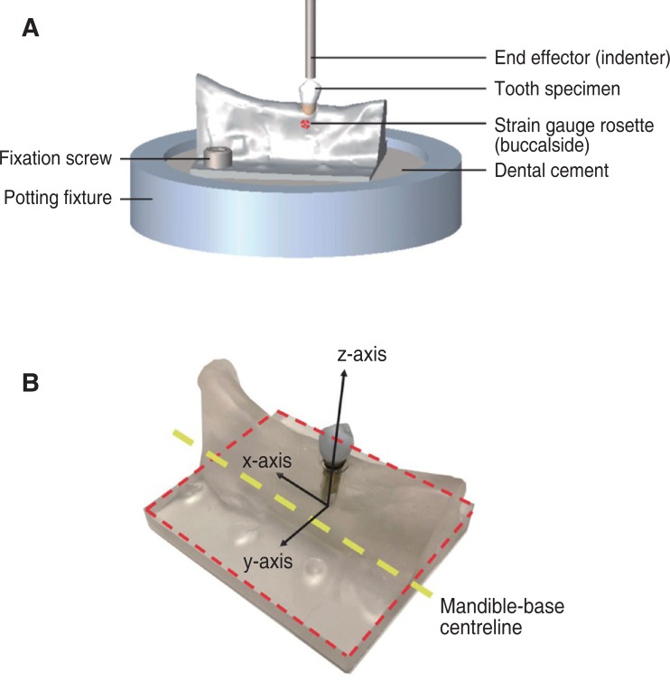
Fig. 2
Position of point loads applied to the landmarks on the occlusal surface in finite element model simulations, including the buccal cusp (yellow), cuspal inclination (green), central groove (pink), mesial marginal ridge (black), distal marginal ridge (red), mesial fossa (brown), distal fossa (purple) shown on the lingual side of tooth (A), right view (B) and left view (C).
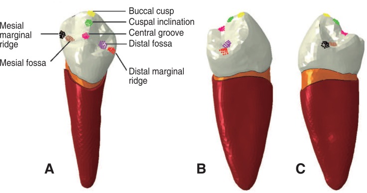
Fig. 3
Force-displacement curves measured experimentally and predicted by the finite element models for the natural and implant tooth assemblies (A), principal strains measured experimentally for the natural tooth on the lingual and buccal sides of the mandible compared to strains calculated using the finite element model (B), and principal strains measured experimentally for the dental implant on the lingual and buccal sides of the mandible compared to strains calculated using the finite element model (C).
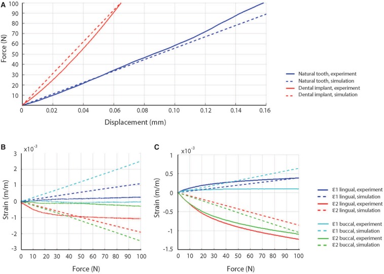
Fig. 4
Contour plots of von Mises stress distributions predicted for the natural tooth (A) and dental implant (B). Data are given for occlusal loading applied at the mesial fossa, distal fossa, buccal cusp, central groove, cuspal inclination, mesial marginal ridge, and distal marginal ridge.
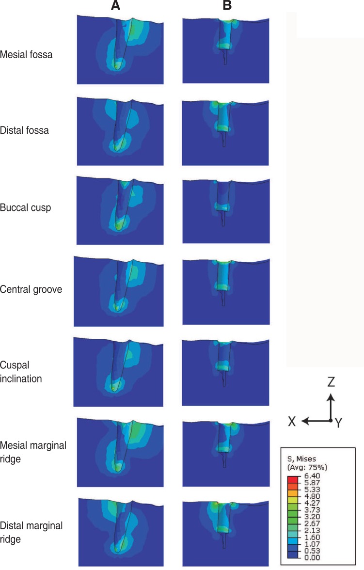
Fig. 5
Maximum von Mises stresses (A), maximum principal strains (B) and minimum principal strains (C) predicted at the mandible for the natural tooth and dental implant assembly. Data are shown for occlusal loading applied at the mesial fossa, distal fossa, buccal cusp, central groove, cuspal inclination, mesial marginal ridge, and distal marginal ridge.
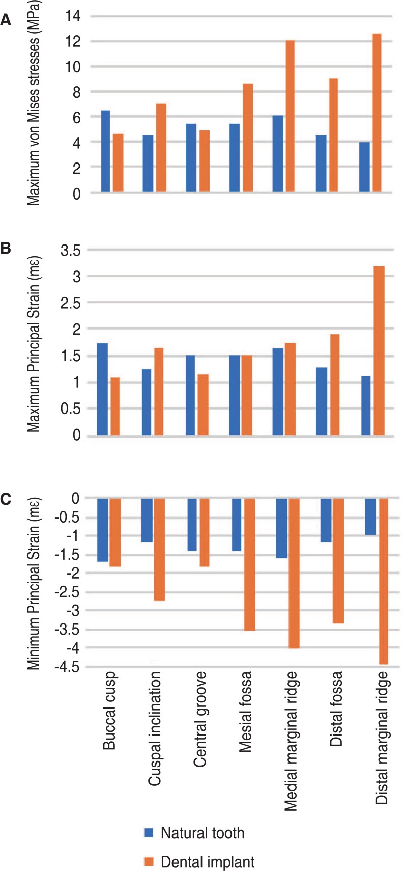
Fig. 6
Micro-CT image of natural tooth from a cadaveric specimen (A), 3-dimensional reconstruction of entire rightside of the mandible from micro-CT images (B), and resulting density map for the natural tooth (C) and prosthetic tooth (D).
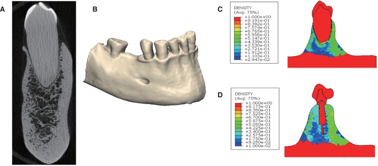
Table 1
Maximum reaction moments calculated during 100 N loading on the crown of the natural tooth and dental implant assembly. Given are the moments (in Nmm) calculated when the occlusal force was applied at the mesial fossa, distal fossa, buccal cusp, central groove, cuspal inclination, mesial marginal ridge, and distal marginal ridge

Table 2
Stresses and strains calculated during occlusal loading of the natural tooth. Values provided are the maximum von Mises stress (MPa) and the maximum, minimum principal strains (mε) when the occlusal load was applied at the mesial fossa, distal fossa, buccal cusp, central groove, cuspal inclination, mesial marginal ridge, and distal marginal ridge

Table 3
Stresses and strains calculated during occlusal loading of the dental implant. Values provided are the maximum von Mises stress (MPa) and the maximum, minimum principal strains (mε) when the occlusal load was applied at the mesial fossa, distal fossa, buccal cusp, central groove, cuspal inclination, mesial marginal ridge, and distal marginal ridge

Table 4
Maximum von Mises stresses calculated during occlusal loading of the natural tooth and dental implant. Data are given for occlusal load applied at the mesial fossa, distal fossa, buccal cusp, central groove, cuspal inclination, mesial marginal ridge, and distal marginal ridge


 PDF
PDF ePub
ePub Citation
 Print
Print


 XML Download