

 PDF
PDF ePub
ePub Citation
 Print
Print


Introduction
Cone-beam computed tomography (CBCT) has become essential for various diagnostic purposes and is widely used in dental practice. The need for optimization is also increasing, and assessments of radiation dose and image quality are required for optimization.1 The image quality of CBCT images can be influenced by many factors, such as spatial resolution, noise, contrast, and artifacts.2
Spatial resolution refers to the ability of a system to distinguish small details, and it is one of the most important factors that contribute to image quality.23 In general, spatial resolution can be measured easily using a line pair chart, but line pair charts cannot yield detailed and objective results.34 Recent studies have used the modulation transfer function (MTF) parameter to measure spatial resolution, and Nakahara et al. recommended using MTF values instead of line pair values for routine quality assurance programs.3 In previous studies, the MTF has been measured in different conditions, with varying devices, phantoms, and exposure conditions.35678910 This variation makes it difficult to compare MTF values across studies, and it is impossible to determine reference values for optimization or quality assurance of CBCT images. Given these difficulties, the SedentexCT guidelines recommend using the initial value of MTF as a reference for spatial resolution in quality control programs.1 Nonetheless, it remains necessary to identify the factors affecting MTF measurements and to quantify their effects to solve these difficulties. This study investigated the effects of voxel size, the oversampling technique, and the direction and area of measurement on MTF values to determine the optimal method of MTF measurement.
Materials and Methods
The CBCT images were obtained using an Alphard Vega device (Asahi Roentgen Co., Ltd, Kyoto, Japan) at Dankook University Dental Hospital. The point spread function (PSF) insert in the SedentexCT IQ phantom (SedentexCT IQ, Leeds Test Objects Ltd., Boroughbridge, UK) was used to calculate the MTF. The PSF insert is made of a stainless steel wire (diameter: 0.25 mm) suspended in the air. In order to identify the optimal method of MTF measurement, factors affecting the MTF were investigated using a 3-step approach.
Effect of voxel size and number of oversampling lines
The PSF insert was placed at the center of the phantom and scanned using 3 different voxel sizes (0.1 mm, 0.2 mm, and 0.3 mm) with settings of 80 kV and 8 mA (the standard settings for adult patients). The MTF 50 and 10 values were calculated using the fast Fourier transform method from 1-dimensional PSF using the MATLAB program (R2016b; Mathworks Inc., Natick, MA, USA). The MTF values were measured with 5 oversampling techniques (1, 7, 11, 15, and 21 combining lines) in 5 axial slices of all images to obtain a reliable result. In total, 100 MTF values were measured in each voxel size group (4 directions, 5 slices, and 5 oversampling techniques).
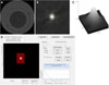
In the axial images, the wire area was magnified, and the image contrast was increased to locate the exact center of the wire. When the window level and width were adjusted until the center of the wire was seen within 5 pixels and the brightest pixel was set as the center, the MTF values of 4 directions (vertical, horizontal, and 2 diagonals) were calculated automatically (Fig. 1).
Error correction efficacy of oversampling techniques
Measuring the MTF from pixel values of 1 line may be subject to error depending on the location of the center of the wire. The oversampling technique integrates adjacent pixel values to compensate for these errors and provide more reliable and smoother MTF curves.6 To verify the necessity and validity of the oversampling technique, the MTF 10 values were calculated with simulated location errors and compared to the correct MTF 10 values without errors. Three location errors (1 pixel left, 1 pixel up, 1 pixel up and left) were simulated in the setting of the wire center in all images.
MTF 10 values according to the direction and area of measurement
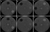
The PSF wire insert was sequentially placed in the center and in 3 peripheral areas (left, upper, and upper-left areas) and CBCT scanning was performed using the P mode (field of view: 154 mm×154 mm; voxel size: 0.3 mm) to obtain an image encompassing the center and periphery. MTF values according to direction (radial and tangential) and area were measured using the optimal oversampling techniques (11 and 15 oversampling lines) for 0.3-mm voxel images, as determined in previous steps (Fig. 2).
Statistics
Statistical analysis was performed using IBM SPSS Statistics version 21 (IBM Corp., Armonk, NY, USA). Based on the characteristics of the samples, analysis of variance (ANOVA), the Wilcoxon-signed rank test, and the independent t-test were used to assess the differences between MTF values. A statistical significance level of P<0.05 was used.
Results
Effects of voxel size and the number of oversampling lines
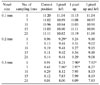
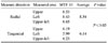
MTF values according to voxel size and the oversampling technique are presented in Table 1. As the voxel size increased, the MTF values decreased significantly, but not proportionally to the increase in voxel size. MTF 50 showed a stable standard deviation only in the 0.1-mm voxel images. MTF 10 showed stable standard deviations in the 0.1-mm and 0.2-mm voxel images. Stable MTF values could be obtained by using 0.1-mm voxel images. In general, MTF 10 showed more stability (smaller standard deviations) than MTF 50. In the 0.3-mm voxel images, the standard deviations of the MTF 50 values exceeded 20% in some oversampling groups, and the standard deviations of the MTF 10 value were less than 10% only in the groups with 11 and 15 oversampling lines.
Error correction efficacy of the oversampling techniques
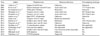
Table 2 shows the MTF values of the oversampling techniques according to the simulated location errors. In the 0.1-mm voxel images, there were no significant differences in the MTF 10 values regardless of the simulated location error or oversampling technique. In contrast, only the oversampling techniques of 11 lines or more did not show significant differences in the 0.3-mm voxel images with simulated errors.
MTF values according to the direction and area of measurement
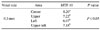
To investigate the effect of the direction and area of measurement, the 0.3-mm voxel images were used to obtain images encompassing the center and 3 peripheral areas. Only the MTF 10 values of the groups with 11 and 15 oversampling lines were used, as determined in previous steps. The MTF 10 values of all 3 peripheral areas were significantly lower than the values of the central area (Table 3). The MTF 10 values of the radial directions were significantly higher than those of the tangential directions in the peripheral areas (Table 4).
Discussion
Although the gold standard for image quality is a subjective evaluation of whether it is appropriate for clinical purposes, quantitative measurements of physical factors are useful for optimization, quality control, and performance evaluation.2311 MTF values are a useful quantitative factor for evaluating spatial resolution. In a systematic review published in 2017, Oliveira et al. found that 25 quality assurance phantoms were in use or under development for CBCT imaging.10 Among those phantoms, 3 evaluated spatial resolution with line-pair bar patterns and 10 measured the MTF from wires, foil, plate or spheres. Recent studies have used MTF values more than conventional bar patterns due to the subjectivity of bar patterns. Although various phantoms and methods have been used, studies on the standardization of these conditions are rare.35678910 This study investigated the effects of voxel size, the oversampling technique, and the direction and area of measurement on MTF values to determine the optimal method of MTF measurement.
In this study, the most stable and highest MTF values were obtained using 0.1-mm voxel images. These results are consistent with previous studies reporting that MTF values decreased as voxel size increased.612 The SedentexCT guideline recommends that spatial resolution should have a variability of less than 20% compared to its initial value.1 Therefore, for quality control programs, using smaller-voxel images would be more accurate due to their smaller standard deviation. However, larger voxels do not always mean lower diagnostic accuracy.1314 Özer reported that there were no significant differences in accuracy in the diagnosis of root fracture among CBCT images of different voxel sizes.13 Liedke et al. reported that voxel size did not influence the diagnostic accuracy of external root resorption.14 It is important to use the proper resolution and radiation dose for each diagnostic task.
The oversampling technique compensates for location errors that may occur in MTF measurements, but few studies have investigated oversampling techniques in CBCT images, and those studies did not verify the effect of oversampling on error compensation.67915 In this study, location error did not cause any significant error in the 0.1-mm voxel images, even without the oversampling technique. In the 0.3-mm voxel images, there were significant differences in MTF values due to location error, and a proper oversampling technique of 11 lines or more was helpful to compensate for these errors. The location errors were made by shifting by 1 pixel, and it is thought that the larger the size of the pixel, the greater the effect of the error. Furthermore, as the number of oversampling lines increased, the MTF values became lower, and it is considered that more areas of surrounding noise were included with increased oversampling.
The measurement area is also an important factor. The MTF values of peripheral areas were lower than those of the central area, which is consistent with previous studies. Ozaki et al. and Kwon et al. reported that the MTF degraded significantly towards the periphery of images.715 However, there is no standardized method of measuring spatial resolution in terms of where representative measurements should be made or whether the center and periphery should be considered together. More research and discussion are needed about techniques for measuring the spatial resolution of CBCT devices and images.
The type of phantom used and the direction of measurement are also important. Previous studies used various kinds of phantoms, such as copper foil, aluminum spheres, coil plates, steel wires, tungsten wires, nickel-chromium wires, and Quart DVT, CTP528, and QAT phantoms (Table 5). Wire phantoms have been most commonly used, as it is thought that bar patterns, foil, and plates make it difficult to measure the MTF in multiple directions. According to the results of this study, measuring the MTF in multiple directions is important, as the radial and tangential directions showed clearly different MTF values. Ozaki et al. and Watanabe et al. also reported that the MTF values differed depending on the direction.67 In some studies, the MTF was measured horizontally and vertically in the axial plane.381216 Making measurements in the vertical and horizontal directions would not be a problem for the central area, but could be a problem when measuring MTF from peripheral areas. CBCT uses rotating geometry, and the horizontal direction would be recognized as a tangential direction in the upper area and as a radial direction in the lateral area.
In conclusion, to obtain more accurate and stable measurements of MTF values, it is better to measure MTF 10 values with small-voxel images. In large-voxel images, the proper oversampling technique is required. MTF values obtained from radial and tangential directions may be different, and MTF values vary depending on the measured area. Therefore, further research is required to standardize the methods of obtaining MTF measurements.

 XML Download