Abstract
Although the current internationally recommended standard for the use factor (U) applied to CyberKnife is 0.05 (5%), the CyberKnife shielding standard is applied more stringently. This study, based on clinical data, was aimed at examining the appropriateness of existing shielding guidelines. Sixty patients treated with G4 CyberKnife were selected. The patients were divided into two groups, according to whether they underwent skull or spine tracking. Based on the results, the use factors for each wall ranged from 0.028 (2.8%) to 0.031 (3.1%) for the intracranial treatment and 0.020 (2.0%) to 0.022 (2.2%) for the body treatment. Excessive barrier thickness resulted in inefficient use of space and higher cost to the institutions. Furthermore, because the use factor is influenced by the position of the robot, the use factor determined based on the clinical data of this study would facilitate more reasonable treatment room design.
Go to : 
REFERENCES
1.NCRP Report 44. Radiation Protection for Particle Accelerator Facilities. Bethesda. 2003. 78–82.
2.NCRP Report 49. Structural shielding design and evaluation for medical use of x-rays and gamma rays of energies up to 10 MeV. 1976.
3.McGinley PH. Shielding techniques for radiation oncology facilities. 2nd edition.Madison: Medical Physics Publishing;2002.
4.NCRP Report 151. In Structural shielding design and evaluation for megavoltage x-and gamma-ray radiotherapy facilities. 2010.
5.Henzen D., Schmidhalter D., Zanella CC, et al. Evaluation of clinically applied treatment beams with respect to bunker shielding parameters for a CyberKnife M6. J. Appl. Clin. Med. Phys. 2018. 19(1):243–249.

6.Purwar AK., Lee MY., Rogers JE. Tenth-value layer measurements of leakage radiation and secondary barrier shielding calculations for the CyberKnife robotic radiosurgery system. Accuray White paper. Sunnyvale, CA, Accuray. 2009.
7.Rodgers JE. CyberKnife treatment room design and radiation protection, Chapter 5. CyberKnife Society Press;2005.
8.Rodgers JE. TVLs of common shielding materials for a robotically mounted stereotactic radiosurgery machine. J. Applied. Clin. Med. Phys. 2005. 157–164.
9.Yang J., Wu W., Hasson B. An evaluation of the use factor for instantaneous dos rates for CyberKnife shielding design. AAPM Annual Meeting, Scottsdale, AZ. 2007. 27–30.
10.Yang J., Feng J. Radiation shielding evaluation based on five years of data from a busy CyberKnife center. J. Appl. Clin. Med. Phys. 2014. 15:313–322.

11.Echner GG., Kilby W., Lee M. The design, physical properties and clinical utility of an iris collimator for robotic radiosurgery. Phys. Med. Biol. 2009. 54(18):5359–5380.

12.Rogers JE. Radiation therapy vault shielding calculation methods when IMRT and TBI procedure contribute. J. Appl. Clin. Med. Phys. 2002. 2:57–64.
13.Diebel J. Representing Attitude: Euler Angles, Unit Qua-ternions, and Rotation Vectors. Matrix. 2006. 58:1–35.
14.Eric W. Weisstein. Euler angles. From MathWorld-A Wolfram Web Resource.http://mathworld.wolfram.com/Cayley-KleinParameter.html. 2009.
15.Arend L. Quaternions, finite rotation and euler parameters. 2002.
Go to : 
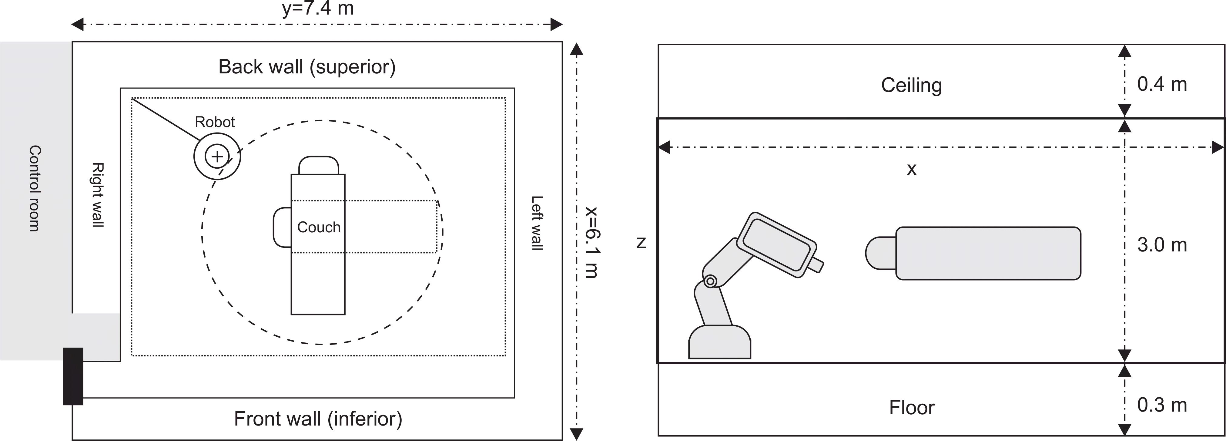
 | Fig. 1G4 CyberKnife treatment room coordinate system. Draw of the CyberKnife treatment room with indicated dimensions and coordinate system. |
 | Fig. 3The history of prescribed iso-dose line (a), the number of beam (b) and total MU of patients (c). |
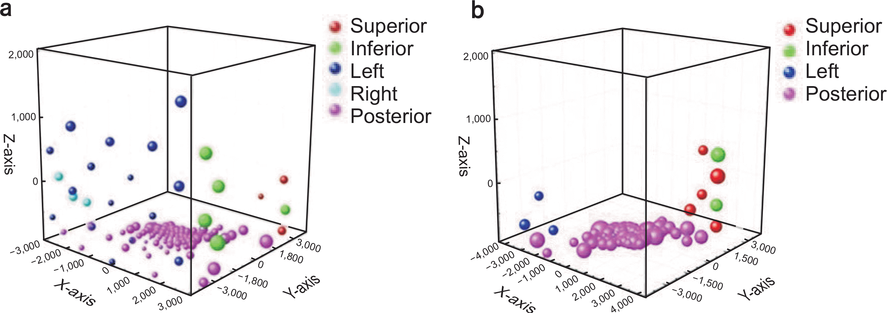
 | Fig. 4The projection of radiation beams for each tracking mode in CyberKnife, (a) skull tracking-beam intensity, (b) spine tracking-beam intensity (Superior: Front wall, Inferior: Back wall, Anterior: Ceiling, Posterior: Floor). |
Table 1.
Characteristics of CyberKnife clinical workload data.
Table 2.
The analysis of MU and use factor (U) for each projection in CyberKnife treatment room.


 PDF
PDF ePub
ePub Citation
 Print
Print


 XML Download