

 PDF
PDF Citation
 Print
Print


INTRODUCTION
Pelvic fractures in dogs are often complex and their reduction can be challenging [1]. In human surgery, preoperative planning and contouring of plates in complex fractures has been documented to improve the quality of the reduction as well as decrease the surgery time and complication rate [23].
The precise preoperative contouring of plates is possible only when a similarly sized anatomical model is available, which is challenging in veterinary patients of various sizes and breeds. The increasing availability of computed tomography (CT) and three-dimensional (3D) printing has paved the way for the use of 3D printed models to replicate a complex bone-surface anatomy. Several veterinary and human studies have reported the printing of bone models to plan surgery [4567]. To be reliable, a 3D printed model should reproduce the morphology of the bone to a fidelity sufficient for surgical planning, but this has not been defined. The reliability of the 3D printing process for the femoral bone in dogs has been reported [8]. On the other hand, there is no literature evaluating the reliability of 3D printing of geometrically complex bone, such as a canine pelvis.
Several 3D printing methods are currently available [910]. Selective laser sintering uses a process of high-powered laser fusion with a powdered material [9]. Stereolithography, historically the first method of 3D printing, relies on the polymerization of a liquid resin using a UV low-powered laser [910]. Fused deposition modeling technology (FDM) is currently the most common printing method and relies on the sequential deposition of fused plastic layers [1112]. Stereolithography and FDM depend on the design and printing of support parts to act as a scaffold of shallow slopes and overhangs. The support elements need to be trimmed after printing. The entire process can result in an irregularity of the surface of the printed model [913].
Dual-material FDM technology allows for the printing of models with different polymers [12]. Some of those polymers designed specifically to be used as a support material are either dissolvable (Polyvinyl alcohol PVA) or are made to breakaway (polyurethane and polylactic acid blend, Breakaway, Ultimaker, Netherlands) easily from other polymers. This allows for a 3D model with a smoother and more regular surface.
This study examined the accuracy and precision of measurements obtained on dual-material FDM (dm-FDM) 3D printed models by a comparison with the measurements of anatomical images obtained by CT. The hypothesis was that measurements of the anatomic segments on a dm-FDM printed model and CT data would be in agreement, indicating that the 3D printed models reproduce the CT data reliably, which is essential for orthopedic use.
MATERIALS AND METHODS
Ten dogs of different sizes were selected opportunistically among patients requiring a CT of the pelvic region for reasons unrelated to the study. The owners' consent was obtained, and the study was performed following the ethical guidelines of the research institution (IACUC 20170501). The procedure was performed under general anesthesia (acepromazine 0.5 mg/kg, Calmivet, Vetoquinol, France; buprenorphine 10 µg/kg, Buprevet, Virbac, France; Alfaxalone 1 mg/kg, Alfaxan, Jurox, United Kingdom; plus isoflurane relay, Vetfluran, Virbac), and the anatomical region of the pelvis was imaged with a four slice CT scan Lightspeed plus (General Electric, General Electric Medical System, France). Image acquisition was performed according to the patient size, following routine protocols selected to limit both the length of anesthesia and the X-ray dose delivered to the patient. The conditions were as follows: FOV 50 cm, slice thickness 2.5 mm, 120 kV, and 153 mA for dogs weighing less than 15 kg; and FOV 50 cm, slice thickness 2.5 mm, 120 kV, and 240 to 383 mA for dogs weighing more than 15 kg [8]. The acquisitions were performed with a 1.5 pitch and proprietary helical interpolation algorithms (Bone, General Electric, General Electric Medical System) were used without edge enhancement. The reconstruction interval was set to 2.5 mm. The pelvises were evaluated for any abnormalities, including but not limited to signs of degenerative joint disease, and were excluded if any were found.
File and 3D printing
Standard tessellation language (STL) files were generated from the DICOM images. Segmentation, thresholding, and exportation of the models were performed within the CT-scan software (Advantage Workstation 4.3, General Electric Medical System). The osseous structures of the pelvic area were isolated from the surrounding soft tissues based on their density measured in Hounsfield units (superior to HU 226). Further individualization of the pelvis from the sacrum, coccygeal vertebrae, and femora was done automatically using the software based on their anatomical separation (i.e., sacro-iliac joints and coxo-femoral joints). A visual inspection of the segmentation was performed to confirm its accuracy. Two hemipelvises (right and left) were printed for each dog, but only the right ones were used in this study. The 3D models were printed by a professional company (3D ArcWest, France) using a professional grade 3D printer (Stratasys 1200 sst, Eden prairie, USA). The printing materials used were ABS (acrylonitrile butadiene styrene) for the model and hydrosoluble PVA for the support with a layer height of 200 microns. All pelvises were printed in a similar orientation with the long axis parallel to the printing surface. Upon printing, the dissolvable PVA was washed away with water and the pelvis was left to dry.
Measurements on printing model and geometric coordinate acquisitions
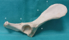
Five anatomical landmarks (Fig. 1) [14] were chosen based on the observers' ability to localize them on both the 3D printed model and CT scan images, and were assigned a letter as follows: A, ischiatic tuberosity at its most distal aspect; B, ischiatic spine at its most dorsal aspect; C, insertion site of the rectus femoris, as characterized by its raised area on the lateral surface of the body of the ilium; D, caudal dorsal iliac spine, also known as the eminence of the iliac crest; and E, cranial dorsal iliac spine, which is defined anatomically as the obtuse angle between the cranial and dorsal border of the iliac spine [15]. All three observers had prior clinical experience in measuring 3D rendered models on a computer and gross measurements on the anatomic specimen. The comparison of the 3D printed models with the CT scan images was based on the length of four segments: BC, AE, BD, and CD. Prior to the beginning of the study, the observers came to an agreement on a standardized methodology for the measurements. The three different observers repeated each series of measurements twice.
Fig. 1
Anatomic landmarks used for the measurements on a gross specimen. (A) ischiatic tuberosity at its most distal aspect; (B) ischiatic spine at its most dorsal aspect; (C) insertion site of the rectus femoris, as characterized by its raised area on the lateral surface of the body of the ilium; (D) caudal dorsal iliac spine also known as eminence of the iliac crest; and € cranial dorsal iliac spine, defined anatomically as the obtuse angle between the cranial and dorsal border of the iliac spine.
On the CT-scan images using the CT-scan software, the automatically calculated (x, y, z) coordinates of the anatomical landmarks were recorded and used to calculate the length between the landmarks using the formula, lab = √ [(xa−xb)2+(ya−yb)2+(za−zb)2], which is derived from the Pythagorean theorem (Fig. 2).
Fig. 2
Illustration of how the coordinates of the anatomical landmarks in a three plane Cartesian system were used to calculate the distance between the aforementioned points.

Direct measurements of the lengths of the four segments were performed on the 3D models with a scientific digital caliper with a precision of 0.1 mm on each printed model. Using this method and the concept of geometrical analysis, a limited evaluation of the pelvic morphology was also performed [1617].
Statistical analysis
All measurements were recorded in centimeters to two decimals (Tables 1 and 2); the measurement differences between the averages of the measurements of both methods were calculated and expressed as absolute values (Table 3). The interobserver agreements and comparison between the measurements obtained were evaluated using the concordance correlation coefficients (CCC) [181920]. Statistical analyses were performed using the software R 3.2.3 and its agreement package (R Foundation for Statistical Computing, Vienna, Austria). The statistical tests allowed an assessment of the precision (i.e., index of variability of the measurement) and accuracy (i.e. are all measurements centered on the same value). The precision and accuracy were evaluated according to a currently published scale [21], with agreement considered perfect, almost perfect, substantial, moderate, or poor when= 1.0, > 0.99, 0.95–0.99, 0.90–0.95, or < 0.90, respectively [21].
Table 1
Measurements for each anatomic segment, as obtained on the three-dimensional printed models

Table 2
Measurements of each anatomic segment, as obtained on the computed tomography data based on the coordinates of the anatomical landmark and the formula, lab = √ [(xa−xb)2+(ya−yb)2+(za−zb)2]

Table 3
Average of the measurements obtained among all three observers and both observations separated between measurements based on the 3D printed models and the measurements obtained on the CT data

RESULTS
The precision and accuracy of repeated measurements using the caliper on the 3D printed pelvises by the three observers were almost perfect for the AE anatomical line (precision: 0.998; accuracy: 1; Table 4). The caliper measurements of BD, BC, and CD showed substantial precision (0.982, 0.969 and 0.962 for BD, BC and CD, respectively). The accuracy of the measurements of BD and BC were perfect and almost perfect, respectively (accuracy: 1.00 and 0.984, respectively). On the other hand, the caliper measurements of CD showed only moderate accuracy (0.934).
Table 4
Intra-observer, inter-observer (k = 3), and total agreement between repeated measurement (m = 2) of anatomical lines on 3D-printed pelvises and on CT-scan volume reconstruction (n = 10)

The precision of repeated measurements on the CT data by the three observers was almost perfect for AE (0.996), substantial for BC and BD, and moderate for CD (0.969, 0.958 and 0.942, respectively). The accuracy was almost perfect for AE and BD (0.999 for both measurements), substantial for BC, and moderate for CD (0.977 and 0.938, respectively; Table 1).
The accuracy of measurements between both methods was > 0.99 for all measurements (Table 5). The precision was almost perfect for AE (0.996) and substantial to moderate for the other measurements (0.963, 0.958, and 0.912 for BD, BC, and CD, respectively).
Although the measurements did not show perfect precision between methods, they were very accurate. This indicates that, on average, the length of each segment measured was almost identical, irrespective of the method used.
Table 5
Intra-methods, inter-methods (k = 2), and total agreement between repeated measurements (m = 6) of anatomical lines on the three-dimensional-printed pelvis (n = 10)

DISCUSSION
The current results indicate that a dual-FDM 3D printer reliably and accurately reproduces the size and geometry of the pelvis, as measured on CT-scan. The pitfalls of this study were fivefold. First, being a prospective and opportunistic study, the CT parameters varied between patients and were chosen on a clinical basis and not optimized for 3D image printing [2223]. Ideally, repeating the CT-scan with a smaller FOV and smaller slice thickness (submillimeter) is needed. This would have resulted in an increased dose delivered to the patient and anesthesia time, both of those being considered questionable ethically by the authors. On the other hand, as these results indicate a high degree of accuracy between the 3D models and the CT data, despite the use of thicker slices, it would appear intuitive that thinner slices, 1mm slices, having been described as having higher accuracy [23], would have improved the accuracy of the models further and strengthened the study results.
Second, as this was an opportunistic design, none of the dogs used in the study underwent a necropsy, which prevented a comparison between the data and the gold standard of gross pathology. Despite this, CT is an accurate way to evaluate and represent the anatomy [2425262728]. Therefore, one could logically assume that if the printed pelvises match the CT images, they would also match the gross anatomy.
Third, in the current study, the scale designed by McBride [21] was used to interpret and define the agreement between the observers and methods. Although used widely, it may not reflect a relevant evaluation of the precision and accuracy required for clinical purposes. Designing a scale adapted to this question would have required a definition of what a clinically acceptable difference in size between a bone and its 3D printed model is, but this was beyond the scope of the present study and would likely be controversial.
Fourth, the morphology comparison of the 3D printed models and CT data relied on the analytic geometry. By comparing the distances between multiple points located on 3D different planes, a limited comparison of the geometry was also performed. This is most apparent when the measurements BC, BD, and CD are compared to one another as they produce a pyramidal shape. If the geometry of the pelvis between the 3D model and the CT data were to be discordant, there would be further discrepancies among the three measurements [17]. More advanced and thorough methods, such as optical 3D scanning [8] and surface shape analysis would have provided additional information on the accuracy between the model and the CT data but this was unavailable to the authors.
Lastly, there is considerable variation in the methods available to produce the 3D models from the CT data and further additional parameters to print the models, which could have influenced the study results. On the other hand, the technologies, parameters and methods (four slice CT, standard bone kernel protocol, 2mm slice thickness, FDM printer, 200 microns resolution, use of common polymers) used in this research were chosen as being readily available and clinically reproducible [23]. Hence, this is likely to be clinically applicable to veterinary surgeons in the future.
FDM printers are readily available, cost effective, and do not require extensive maintenance [23]. Being the most popular of consumer grade 3D printers [23], they will most likely be the type found in veterinary hospitals and clinics in the near future. In human medicine, several studies have reported strong accuracy between CT scans combined with 3D printing techniques to produce different bone models, such as a skull or mandible [2930]. The veterinary scientific literature currently available lacks thorough studies evaluating this new technology. Several veterinary publications have described the use of 3D printing in the planning of angular limb correction surgery without confirming whether the printed model represents the shape of the bone reliably [313233]. A single veterinary publication validated both steps by studying the concordance between the shape of the femur and printed models after different acquisition and printing methods, but it did not evaluate the use of dm-FDM [8] nor did it evaluate their methods for a more geometrically complex bone, such as the pelvis.
The minor differences in measurements between the CT data and 3D printed models were due most likely to a combination of the described above pitfalls.
When printing shallow slopes and complex shapes with FDM, a support material acting as a scaffolding is often required. The remnant of the supports after their removal can affect the smoothness, regularity, and accuracy of the object printed [913]. This can be overcome easily with dual-material FDM because it prints two types of material simultaneously, such as one soluble for the support material and another polymer for the 3D model.
Similar to the research conducted in human medicine, the models evaluated in the current study were clinically aimed at improving the planning of pelvic and acetabular surgery [734]. The use of 3D printed models to measure and choose surgical implants can be supported scientifically by demonstrating that on average, the length of each segment measured was almost identical between the two methods using the reported parameters. Additional study evaluating the surface contour of the pelvis more thoroughly would be useful in the future to further support the practice of contouring the surgical implants. The use of 3D printing in the preoperative planning of the surgery has been documented previously to decrease the length, morbidity, mortality, and cost of canine limb deformity treatment [35]. Whether this is also true for the treatment of pelvic fractures has yet to be determined.
In conclusion, this study lays the groundwork in validating the accuracy of 3D printed models when compared to CT-data and therefore to the anatomy in general [252836373839]. Additional studies comparing 3D printed models with anatomical specimens would be beneficial to the field because 3D models are being used more commonly in veterinary medicine to practice surgery, contour implants, as well as to improve communication with clients and students.
Demonstrating that the measurements made on the 3D models are true to those obtained from the CT data is the first step in scientifically validating the use of 3D models for presurgical planning. This opens the pathway for additional studies evaluating the geometry of 3D printed models and determining if the preoperative contouring of plates on 3D models allows a better reduction of the bone when compared to perioperative plate contouring.
 XML Download