

 PDF
PDF ePub
ePub Citation
 Print
Print


INTRODUCTION
En-masse retraction of the maxillary anterior teeth is a critical procedure in orthodontic treatment of protruded anterior teeth. To accomplish this, various methods have been attempted using continuous or segmental approaches from the labial or palatal side.12345678910111213
In the past, the use of continuous archwire mechanics with posterior teeth as anchorage was the most common method for achieving en-masse retraction of the anterior teeth.1235 With this method, some anchorage loss was inevitable since the retraction force is applied to both anterior and posterior teeth. If absolute preservation of anchorage is critical, anchorage loss can be prevented by using temporary skeletal anchorage devices such as anchor screws.4678910111213 However, even with a screw, an unexpected rotation of the whole dentition can occur if a retraction force is not applied in the appropriate manner.
A palatal approach was preferred as an esthetic alternative to the labial approach,23458910111213 but torque control of the anterior teeth was more difficult with the conventional palatal approach using continuous archwire than with the labial approach.4 This difficulty was overcome by using segmented archwires with lever arm mechanics.24581013 A longer lever arm and gingivally higher skeletal anchorage in the palatal approach makes it possible to attain a force system favorable to controlled retraction of maxillary anterior teeth due to the width and depth of the palate.
Several mechanical analyses have been performed to assess en-masse retraction of the anterior teeth.10111213 However, all of them were only limited to the initial tooth movement immediately after the force application. The movement pattern of the anterior teeth was discussed based on the assumption that the movement direction was equal to the force direction, but the relationship between the force application point and the center of resistance (CR) changed as the teeth moved, and thereby the movement pattern also changed. In addition, the movement direction was not always equal to the force direction.14 At present, the precise mechanics of en-masse retraction is not still fully understood.
The aim of this study was to clarify the mechanics of tooth movement for palatal en-masse retraction of the anterior teeth by using anchor screws and lever arms. To achieve this purpose, the finite element method was used to simulate the overall orthodontic tooth movements.
MATERIALS AND METHODS
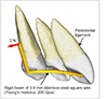
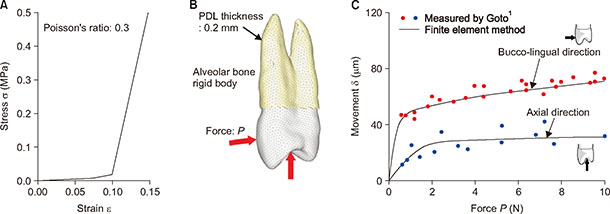
A finite element software, ANSYS 11 (ANSYS, Inc., Canonsburg, PA, USA), was used for the present finite element analysis. Figure 1 shows the finite element model for simulating extraction space closure with en-masse retraction of the segmented anterior teeth. Assuming bilateral symmetry of the arch, only the left side was modeled. Three-dimensional models of the teeth were made based on computed tomography (CT) images of a dental study model (i21D-400C; Nissin Dental Products, Kyoto, Japan).15 Each tooth was meshed with shell elements and defined as a rigid body. The term “rigid” means “undeformable” in the present article. The rigid body was defined by using the multipoint constraint approach provided in ANSYS 11.
The teeth and alveolar bone were assumed to be rigid bodies. The periodontal ligament (PDL) of 0.2 mm thickness was constructed on the root with solid elements.161718 Nonlinear stress–strain relationship of the PDL was approximated with a piecewise linear curve. It was determined based on in vivo measurements of tooth mobility, as shown in Appendix 1.
The palatal wire and lever arm were made from 0.8-mm stainless steel square wire. Considering their elastic deformation, the palatal wire and lever arm were assumed to be elastic beams with a Young's modulus and Poisson's ratio of E = 200 and ν = 0.3, respectively. Using rigid beams, the segmented archwire was firmly fixed to the crowns at the bracket positions. The symmetrical boundary condition was applied at the median end of the wire (Figure 1).
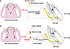
Figure 2 shows the combinations of anchor screw positions and lever arm height. One anchor screw was placed in the midpalatal area. Two anchor screws were placed in high or low positions on the palatal slope. The location of the anchor screws was measured from the bracket position. Forces of 2 N were applied from the anchor screw(s) to the lever arms extended at the canines. This amount of force was the same as the force used in several clinical cases.51213 The lever arm height was 12 mm for the midpalatal screw, and varied by 6 mm, 8 mm, and 10 mm for the palatal slope screw.
The CR of the anterior teeth was determined in the cases where the anterior teeth moved bodily. For this purpose, the anterior teeth were defined as a rigid body.16
Orthodontic tooth movement was assumed to occur by accumulation of the initial movement produced by elastic deformation of the PDL.1718 Long-term orthodontic movement was simulated by the following repeating calculations. First, the initial movement of each tooth was calculated based on the application of a force to the lever arm in the finite element model. In this calculation, nodes on the outer surface of the PDL were fixed, because the alveolar bone was assumed to be a rigid body. Second, the alveolar socket of each tooth, namely nodes on the outer surface of the PDL of each tooth, were moved as a rigid surface by the same translations and rotations as the initial movement. Alveolar bone was not a factor in these calculations. By repeating these two steps, the teeth moved step by step. The force system acting on the teeth was updated at each step. The movement pattern of the teeth changed as the teeth moved. The number of repeating calculations, N, corresponds to the time elapsed after the force application.
RESULTS
Figure 2A and 2B show the location of the CR of the anterior teeth and the line of action of the force with respect to the initial tooth position. Five combinations of screw positions and lever arm height were used to change the force direction. The lines of action of the force passed apical and coronal to the CR in the two combinations of low palatal screws and 10-mm height and 6-mm height lever arms, respectively, and through the CR in the other three combinations.
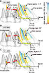
In the three cases where the line of action of the force passed through the CR, Figure 3 shows the movement pattern of the anterior teeth at the number of repeating calculations N = 800. The computational time required for these calculations was about 80 minutes using a personal computer (Intel Core i3, 2.8 GHz, 4GB RAM). The posterior teeth, which were not included in the simulation model, were illustrated in the Figures for observing the relative position with the anterior teeth. Mean stress in the PDL was depicted on the roots with color contours. Red and blue colors indicate compressive and tensile stresses, respectively. The tipping angle of the central incisor is written in the Figures. The positive and negative angles indicate palatal and labial tipping respectively.
For all cases in Figure 3, the anterior teeth translated almost bodily. Compressive and tensile stresses were distributed on the palatal and labial sides of the roots, respectively. In the case with the midpalatal screw, the anterior teeth translated upward (Figure 3A). When the high positioned screws were placed on the palatal slope, the anterior teeth translated with some intrusion although the line of action of the force was horizontal (Figure 3B). In the case of the low-positioned screw, the anterior teeth translated horizontally although the line of action of the force was downward (Figure 3C).
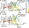
Figure 4A shows the tooth movement pattern in the combination of the low-positioned screw and 10-mm-high lever arms at N = 800. The anterior teeth tipped labially at first because the line of action of force passed apical to the CR, and then translated with the initially produced tipping. Figure 4B shows the case of a 6-mm-high lever arm, where the line of action of the force passed coronal to the CR. The anterior teeth tipped palatally at first and then translated.
DISCUSSION
Mechanics of tooth movement
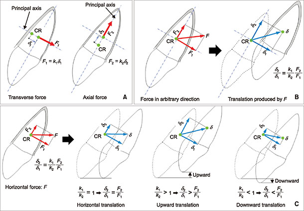
When applying an upward and backward force passing through the CR using one anchor screw placed in the midpalatal area, the anterior teeth translated in a more upward direction than horizontal due to the vertical component of force (Figure 3A). In the cases where two anchor screws were placed on the palatal slope in the high position, the force was horizontal and backward without the vertical component. However, even with a horizontal force passing through the CR, the anterior teeth translated with some intrusion (Figure 3B). This movement direction did not coincide with the force direction. This result seemed to be contrary to common orthodontic sense. Osipenko et al.14 have demonstrated that the tooth movement direction is not always equal to the force direction. Their theory is explained in Appendix 2. When applying this theory to the anterior teeth segment, the ratio of spring constants in the principal directions became k1/k2 > 1, and thereby the teeth translated upward by the horizontal force. This movement pattern was produced due to an inclination of the anterior teeth. If the horizontal force passing through the CR of the anterior teeth is applied perpendicular to their long axis, the teeth must translate in a horizontal direction without vertical movement.
Tooth movement patterns can change depending on the spring constants of the tooth supported with the PDL, k1 and k2, which will be different for each tooth. The movement patterns simulated here are not general pattern but represent specific teeth having the same stress–strain relationship as in Appendix 1.
With regard to the clinical settings, it should be noted that the movement direction is not always equal to the force direction. In a clinical report,4 a force parallel to the occlusal plane was applied to the CR of the six anterior teeth, and although they were guided to move parallel by an archwire, the anterior teeth moved bodily with an unexpected intrusion. To move the anterior teeth bodily without intrusion or extrusion, a downward and backward force passing through the CR was necessary (Figure 3C). This force direction, namely the combination of the anchor screw position and lever arm height, was determined by trial and error. Movement patterns of the anterior teeth could be controlled by changing the height of the lever arm for pure horizontal translation.
The anterior teeth tipped labially and palatally (Figure 4) depending on the line of action of the force that passed apical or coronal to the CR at the initial position (Figure 2B). In these cases, the force systems varied as the anterior teeth tipped, and thereby the line of action of the force passed through the CR after a while (N = 800) (Figure 4). It was difficult to predict these movement patterns using only the initial force systems.
As we demonstrated in this study, tooth movement direction was not always coincident with the force direction. To control movement patterns of the anterior teeth, knowledge of their CR and the relationship between force direction and CR is essential. However, estimation of tooth movement is still difficult because it also depends on each individual property of the PDL, namely the spring constants k1 and k2 in Appendix 2. For this reason, it would be difficult to set an optimal combination of anchor screw positions and lever arm heights to achieve a desired movement pattern. In clinical settings, the movement patterns should be observed carefully and the force direction should be modified if an undesirable movement of the anterior teeth occurs.
Clinical consideration
Palatal en-masse retraction of the maxillary anterior teeth using anchor screws is an alternative method for the correction of lip protrusion. There are various methods to apply retraction force to the anterior teeth.12345678910111213 Anchor screws are quite useful for the en-masse retraction and are superior to conventional orthodontic mechanics because they allow for maximum retraction without any anchorage loss or patient cooperation. Therefore, careful use of anchor screws together with an understanding of the involved mechanical principles can expand the boundaries and scope of conventional fixed appliance therapy. In this study, we investigated the mechanics of palatal en-masse retraction of the anterior teeth by using the finite element method based on the position of anchor screws and height of the lever arm in the palatal area.
Even when tipping movement occurred as shown in Figure 4, the line of action of the force passed through the CR of the anterior teeth after some retraction. This might mean that the anterior teeth could be retracted bodily with the same height of the lever arm or anchor screws after some tipping has occurred. This might be clinically important. If the anterior teeth are labially inclined before treatment, a short lever arm would be necessary to upright the anterior teeth and then the same lever arm height might be used for bodily retraction after achieving a normal inclination, and when the line of action of the force passed coronal to the CR, the anterior teeth tipped clockwise during retraction.
CONCLUSION
By using an overall finite element simulation, the mechanics of palatal en-masse retraction of segmented maxillary anterior teeth were clarified. The following conclusions were obtained:
1. The tooth movement pattern changed depending on a combination of lever arm height and anchor screw position.
2. The maxillary anterior teeth tipped labially or palatally and translated when the line of action of the force passed apical or coronal to the CR.
3. The maxillary anterior teeth translated when the line of action of the force passed through the CR.
4. The maxillary anterior teeth moved bodily with an unexpected vertical movement when the line of the action was not perpendicular to the long axis of the anterior teeth even though the force direction was horizontal and passed through the CR.
5. The tooth movement pattern may be unpredictable in a clinical setting because it is not necessarily the same as the force direction.
 XML Download