

 PDF
PDF ePub
ePub Citation
 Print
Print


INTRODUCTION
Since first being reported by Angell1 in 1860, maxillary expansion has been used as a treatment method for unilateral or bilateral posterior crossbite caused by transverse maxillary constriction, crowding owing to arch length discrepancy, and anteroposterior and vertical problems.2 Transverse maxillary deficiencies cause not only unesthetic dentofacial growth of the tissues around the orofacial area owing to mandibular deviation caused by skeletal maxillary hypoplasia and asymmetrical orofacial growth but also periodontal and functional problems due to dental compensation.3 Since the 1960s, the rapid palatal expander (RPE) has been used as the most effective method for resolving maxillary deficiencies. Conventional RPE is still used today to resolve posterior crossbite, arch length discrepancy, and anteroposterior skeletal problems.4
A study using cast models before and after treatment has reported a transverse expansion of 3.5 to 9.5 mm after RPE. A study of posteroanterior cephalograms reported an average expansion of 6.04 mm after RPE.56 In addition, dental tipping of 0 to 24° on both sides and an average tipping of 3.1° on one side have been reported with the use of RPE.7
In early childhood, when the midpalatal suture is open, maxillary expansion occurs as the force applied to the teeth expands the midpalatal suture. However, when conventional RPE is performed in adults, tooth movements, rather than skeletal expansion, usually occur owing to a closed midpalatal suture. This can cause a tooth to be exposed outside the bone housing and lead to periodontal problems, such as dehiscence.8 Resistance to maxillary expansion occurs throughout the oromaxillofacial area, with the pterygomaxillary, zygomaxillary, and nasomaxillary buttresses offering the strongest resistance. This resistance limits expansion, and a relapse can occur even after transverse expansion, reducing long-term stability of the outcomes.9
To avoid these side effects, clinicians have proposed miniscrew-assisted RPE (MARPE) in which bone-borne-type miniscrews are directly connected to the jack screws of the conventional RPE, and a force is applied directly to the palatine bone.1011 MARPE has also been applied effectively to expand the maxilla in adult patients with a closed midpalatal suture.12 With the use of MARPE, it has become possible to expand the maxilla effectively without causing dental tipping, periodontal problems, and root resorption. It is now also possible to perform MARPE efficiently in patients with long faces by using posterior translation.13
To date, various of forms of MARPE have been proposed and used. Various types and combinations of appliances are used, depending on the clinician's preference and their commercial availability. Lee et al.14 reported that even when MARPE of similar styles are used, the stress distribution and the extent of stress distribution in the maxilla change depending on the expander design and the miniscrew position.15
MARPE doubles orthopedic maxillary expansion and orthodontic dental effects, making it difficult to analyze the extent of orthodontic expansion caused by skeletal expansion and tooth movements. In addition, previous studies have usually analyzed MARPE, which uses teeth as anchors; these studies could not investigate the pure effect of the miniscrews on maxillary expansion. To date, few studies have investigated the effect of the bone-borne RPE design or the number, position, and length of the miniscrews on maxillary expansion. Clinicians have been using mixed MARPE techniques, and accurate information regarding the differences in maxillary expansion related to the design of the appliance is lacking.
In this study, a bone-borne RPE, including miniscrews and jack screws, was used to eliminate the orthodontic effect of MARPE and to investigate the effect of the bone-borne RPE on maxillary expansion. The purpose of this study was to analyze the effects of the number, position, and length of miniscrews used in a bone-borne RPE, and that of the design and positional changes of the expander, on maxillary expansion using the three-dimensional (3D) finite element method (FEM), in order to propose a more effective method of bone-borne rapid palatal expansion in a clinical setting.
MATERIALS AND METHODS
Kee's Bone Expander (BMK Co., Seoul, Korea) was used for maxillary expansion. For miniscrews, C-Implants (C-implant Co., Seoul, Korea) with a thickness of 1.8 mm and lengths of 6, 8, 10, and 16 mm were used. The length of the hook of Kee's Bone Expander was changed depending on the 3D model conditions.
The 3D coordinates consisted of a sagittal plane on the x-axis, a transverse plane on the y-axis, and a vertical plane on the z-axis. The expander was made to expand by 0.25 mm along the y-axis with each turn and was fixed on the x- and z-axes. The stress produced by the expander was analyzed with one turn of the screw and with a maximum force of 2.27 kg.
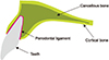
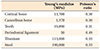
In terms of the physical properties of the maxilla, it was assumed that the maxilla had a linear-elastic, isotropic Young modulus (E) and Poisson ratio (v). The same assumptions as made in previous studies regarding the physical properties of the teeth, alveolar bone, root ligaments, and surrounding tissues were applied in this study (Table 1 and Figure 1).16 The maxillary sutures, including the mid-palatal suture, were assumed to be ossified and were assigned a large modulus of elasticity equal to that of cortical bone.1718
A finite element model was constructed from a computed tomography (CT) image of an adult dry skull using the MIMICS program (ver. 15.01; Materialise, Leuven, Belgium). Visual-mesh software (ver. 7.0; ESI Group, Paris, France) was used for FEM meshing, PAM-MEDYSA (ver. 2011; Pacific ESI, Glebe, NSW, Australia) was used for finite element analysis, and Visual-Viewer (ver. 7.0; ESI Group) was used for post-processing. The distribution of von Mises stress and displacement were analyzed.
Eight experimental groups were generated. The initial position of the expander was located at the midpalatal suture and was centered on the contact between the second premolar and the first molar. In Groups 1, 2, and 3, the effect of miniscrew placement on maxillary expansion was investigated. In Group 1, 8-mm-long miniscrews were placed in the anterior region only. In Group 2, 6-mm-long miniscrews were placed in the posterior region only. In Group 3, 8-mm-long miniscrews were placed in the anterior region, and 6-mm-long miniscrews were placed in the posterior region. In Group 4, the effect of bi-cortical miniscrews on maxillary expansion was investigated. In this group, 16-mm-long miniscrews were placed in the anterior region and 10-mm-long miniscrews were placed in the posterior region for bi-cortical installation.19 In Groups 5 and 6, the effect of the anteroposterior position of the expander on maxillary expansion was investigated. In Group 5, the expander was moved 3 mm from the original position, in the anterior direction. In Group 6, the expander was moved 3 mm in the posterior direction. In Groups 7 and 8, the effect of the length of the hook attached to the expander was investigated. In Group 7, the hook length was increased by 3 mm in the anteroposterior direction, while in Group 8, it was increased by 6 mm in the anteroposterior direction (Figure 2).
Finite element analysis was divided between dental points and skeletal points. The stress distribution and displacement changes at the incisal points of the maxillary teeth and at the following skeletal points: N point, zygomaxillary suture, maxillary tuberosity, nasal bone, nasal base, and anterior nasal spine point, were compared. The stress distribution was presented with different colors according to the magnitude of stress. Six points that divide the midpalatal suture into five equal parts were assigned to the paramedian area, and von Mises stress was compared between the different points. Displacement changes at the dental points were compared using graphs (Figure 3).
RESULTS
Effect of miniscrew position (Group 1 vs. Group 2 vs. Group 3)
The magnitude of von Mises stress in the paramedian area, which is important for maxillary expansion, in each group is shown in Table 2. Displacement changes of the teeth and skeletal points along each axis are shown in Tables 3 and 4.
Based on the stress distribution, the expander affected the anterior region in Group 1, posterior region in Group 2, and anteroposterior region in Group 3. The expansion of the expander also affected the nasal bone (Figure 4A).
In a comparison of stress magnitudes in the paramedian area, Group 3, in which miniscrews were placed in the anterior and posterior regions, showed the greatest stress, and showed an increase in stress approximately equal to the sum of the increases in stress in Groups 1 and 2. Group 3 also showed a greater increase in stress at the second premolar than did Group 2, in which miniscrews were placed in the posterior region only (Table 2).
Group 3 showed the greatest displacement changes along the y-axis owing to transverse displacement of the maxilla, and it also demonstrated a more evident increase in expansion in the posterior region. Along the z-axis, which shows vertical displacements, Groups 1 and 3 showed extrusion in the anterior region and intrusion in the posterior region, overall exhibiting clockwise rotation of the maxilla. In contrast, Group 2 showed counterclockwise rotation. However, the vertical displacement was not large and was approximately one-tenth the amount of transverse expansion (Figure 4B and Table 3).
Effect of miniscrew length (Group 3 vs. Group 4)
Similar stress distributions were observed in all groups as the miniscrew length was increased, with no significant difference between groups. However, Group 3 showed the greatest overall stress in the paramedian area (Figure 5A and Table 2).
In the displacement graph, Group 3 and Group 4 showed similar transverse maxillary displacements. In the z-axis displacement graph, large changes in the movement of the anterior teeth were observed as the miniscrew length was increased. As the miniscrew length increased, greater intrusion was observed in the anterior teeth than in the posterior teeth. Overall counterclockwise rotation and total intrusion, although small in magnitude, were observed (Figure 5B).
Effect of expander position (Group 3 vs. Group 5 vs. Group 6)
Group 3 and Group 6 showed similar stress distributions in all areas except for the nasal bone. Changes in the expander position had a greater influence in the anterior region than in the posterior region in Group 5, the stress distribution tended to decrease (Figure 6A). In the paramedian area, anterior movement of the expander led to increased stress in the anterior region, and posterior movement of the expander led to slightly increased stress in the posterior region. However, the overall magnitude of stress was smaller than that in Group 3, except at the first premolar (Table 2).
In the displacement graph, Group 5, in which the expander was positioned in the anterior direction, showed greater changes in overall transverse displacement than Group 3, except at the second molar. In contrast, Group 6, in which the expander was positioned in the posterior direction, showed smaller changes in overall displacement. In the z-axis displacement graph, Group 5 showed increased clockwise rotation of the maxilla, whereas Group 6 showed an overall total intrusion of the maxilla (Figure 6B).
Effect of hook length (Group 3 vs. Group 7 vs. Group 8)
The stress distribution became slightly smaller in Group 7 in which the hook length was increased by 3 mm, as compared to Group 3. Group 8 showed a slight increase in stress distribution. Group 8 showed a similar overall stress distribution as that in Group 3 (Figure 7A). In the paramedian area, Group 7 showed greater stress at the incisors and second premolars relative to Group 3, and similar or slightly lower stress in all other areas. Group 8 showed lower stress than Group 3 in all areas except for the lateral incisors (Table 2).
Along the y-axis, Group 8 showed slightly greater displacement than Group 3, and Group 7 showed less overall displacement than Group 3. Along the z-axis, Group 8 showed increased clockwise rotation of the maxilla, and Group 7 showed total intrusion of the maxilla overall (Figure 7B).
DISCUSSION
A closed midpalatal suture is a complex structure comprised of cortical bone and cancellous bone, similar to a normal maxilla. An open midpalatal suture, on the other hand, has physical properties similar to those of periodontal ligament.20 The midpalatal suture is usually closed during early maxillary expansion and opens as the expander expands. During this expansion, changes in stress distribution and displacement may be observed due to the altered physical properties of the midpalatal suture. Even when the same type of expander is used, different stress distributions and displacement changes can be observed using the FEM, depending on whether or not the state of the midpalatal suture was considered.21 Lee et al.22 reported that even when the same type of MARPE was used to open the midpalatal suture surgically, the displacement change increased by 5 to 6-fold in the paramedian area and the stress distribution decreased by 4–60-fold.
Previous studies have reported differences in the amount of expansion between the anterior and posterior regions upon expansion with an RPE. However, study results have varied, and there is no consistent evidence regarding whether maxillary expansion occurs in parallel and whether maxillary expansion in the anterior region occurs in a wider triangular form or not. In addition, there are large variations (12% to 52.5%) in the ratio of maxillary expansion relative to the total expansion by the RPE.23
When comparing stress distributions between Groups 1, 2, and 3, the overall palatal stress distribution was highest in Group 3, in which miniscrews were placed in the anteroposterior region. Moreover, the distribution of stress increased not only to the nasal bone but also to the inferior orbital rim. This result was similar to previous findings regarding MARPE and demonstrates that palatal expansion induced by an expander affects not only the maxilla but also the entire maxillofacial region.24 In addition, Group 3 showed the greatest posterior transverse displacements. Approximately 57.5% expansion of the midpalatal suture, from a closed state, was observed. This result was similar to that of Liu et al.23 Thus, placing four miniscrews in the anteroposterior region was more advantageous in terms of stress distribution and transverse displacement.
A previous study reported that the length of miniscrews used in MARPE affected maxillary transverse expansion and that bi-cortical miniscrews have greater stability and allow more horizontal expansion than monocortical miniscrews.25 As shown by the results obtained with Groups 3 and 4, use of bi-cortical miniscrews had no significant effect on stress distribution in the maxilla. However, the magnitude of stress decreased overall in the paramedian area. This may be because when long miniscrews are used, the length of the surrounding bone to which the stress is distributed also increases, leading to an increased surface area, which reduces pressure and consequently stress. Group 4, in which the miniscrew length was increased, showed a slight but non-significant decrease in displacement.
Regarding the change in the transverse displacement of the posterior teeth, Group 5, in which the expander was positioned in the anterior region, showed increased posterior expansion as compared to Group 3 at all regions, except the second molar. However, Group 6, in which the expander was located in the posterior region, showed an overall decrease in posterior expansion. Therefore, placing the expander in the posterior region to increase posterior expansion was not effective from the perspective of displacement change.
Vertical displacement changes were significantly affected by the expander. When the expander was placed in the anterior region, clockwise movement of the maxilla increased. This tendency decreased when the expander was positioned in the posterior region. Comparisons of Group 1 and Group 3, and of Group 3, 5, and 6 showed that anteriorly positioned miniscrews significantly affected the vertical movement of the maxilla. In addition, the presence of miniscrews in the anterior region, or moving the miniscrews toward the anterior region, increased extrusion in the anterior region.
The effect of the expander hook length was observed in Groups 3, 7, and 8. An overall increase in stress was observed in Group 7, in which the hook length was increased by 3 mm. The overall stress decreased, however, when the hook length was increased by 6 mm. Based on this observation, it appears that there is a nonlinear relationship between the stress distribution and hook length. Studies in which the hook length was increased have not shown consistent results regarding changes in the distribution and magnitude of stress, as well as displacement changes. A comparative analysis of hook length and stress distribution is therefore necessary.
A limitation of this study was that we investigated the effect of the expander on maxillary expansion only after a one-turn expansion. There are significant differences in the distribution and magnitude of stress and changes in displacement between when the midpalatal suture is closed and when it is open during early maxillary expansion. Although the changes that occur until the midpalatal suture is opened with an expander are important, additional research on maxillary expansion after the midpalatal suture has been opened may also be useful. In addition, we eliminated the effect of teeth by using a bone-borne RPE. Seong et al.26 reported that MARPE could deliver expansion force to the suture more effectively than bone-borne RPE. Our study, which excludes the effect of teeth, can form the basis for future studies in which anchors are added to the teeth.
CONCLUSION
Anteroposterior placement of miniscrews was the most advantageous in terms of achieving maxillary expansion. Although the miniscrew or hook length and anteroposterior positional changes of the expander did not significantly affect maxillary expansion, they affected vertical positional changes of the maxilla and caused 3D movements of the maxilla.


 XML Download