Abstract
Purpose:
The objective of this study is to evaluate the geometrical accuracy of a patient-specific bolus based on a three-dimensional (3D) printed mold and casting method.
Materials and Methods:
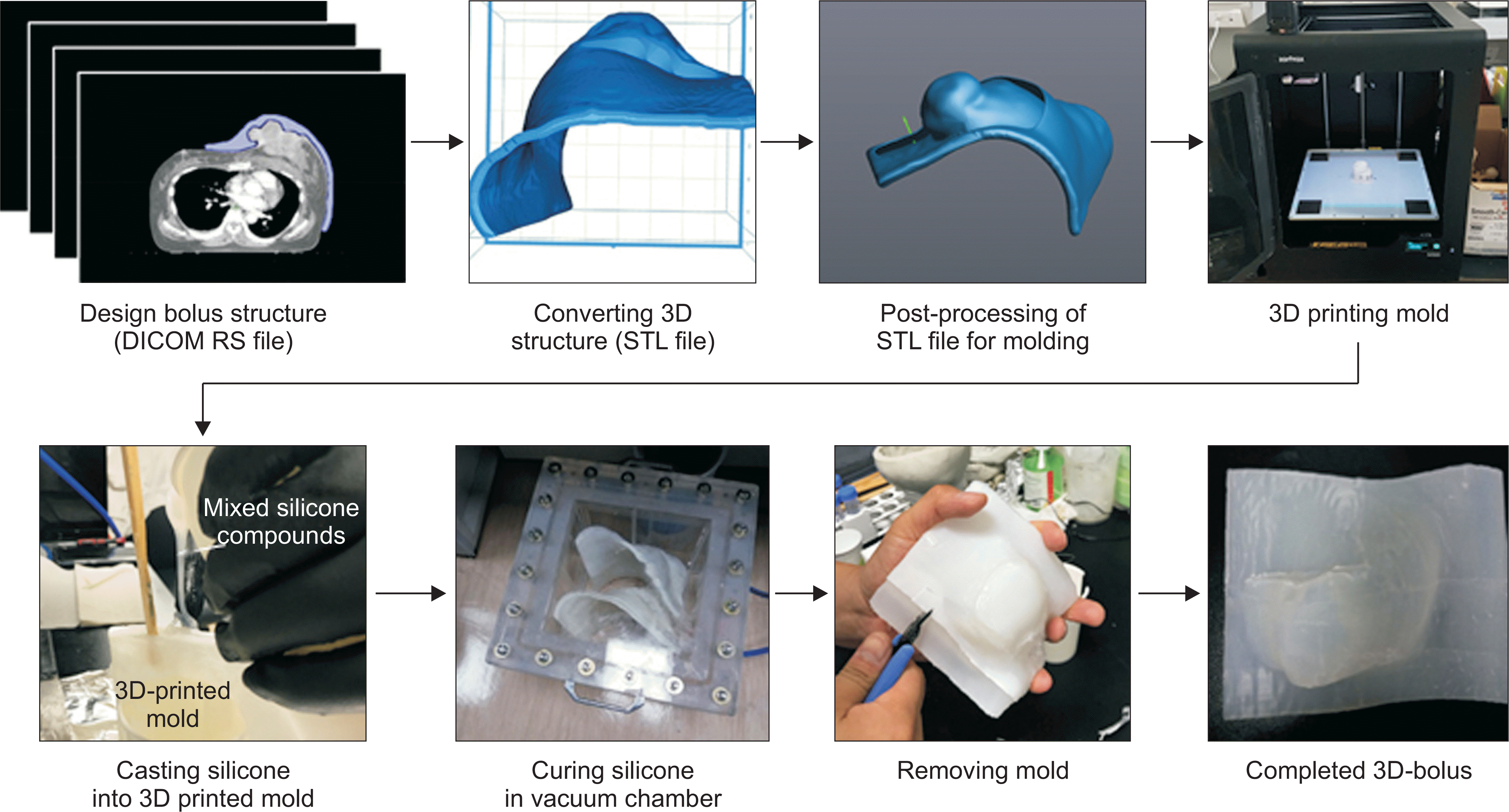
Three breast cancer patients undergoing treatment for a superficial region were scanned using computed tomography (CT) and a designed bolus structure through a treatment planning system (TPS). For the fabrication of patient-specific bolus, we cast harmless certified silicone into 3D printed molds. The produced bolus was also imaged using CT under the same conditions as the patient CT to acquire its geometrical shape. We compared the shapes of the produced bolus with the planned bolus structure from the TPS by measuring the average distance between two structures after a surface registration.
Results and Conclusions:
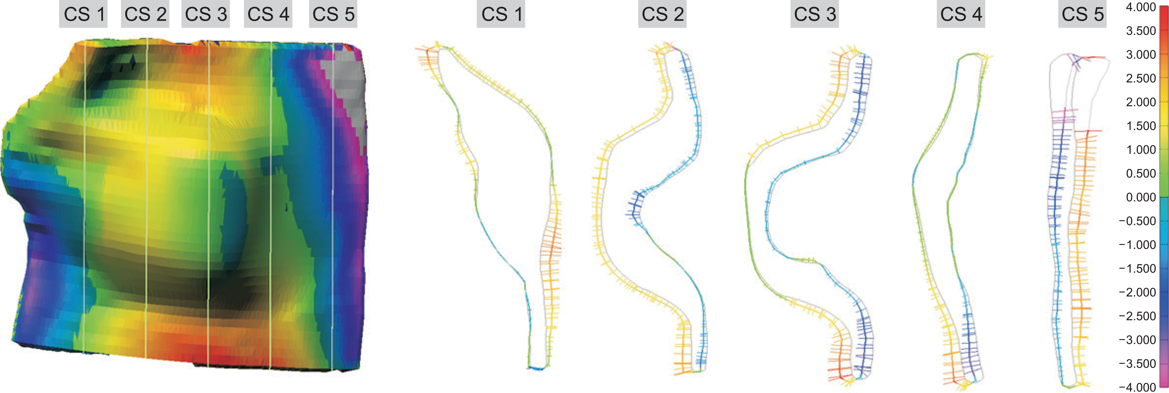
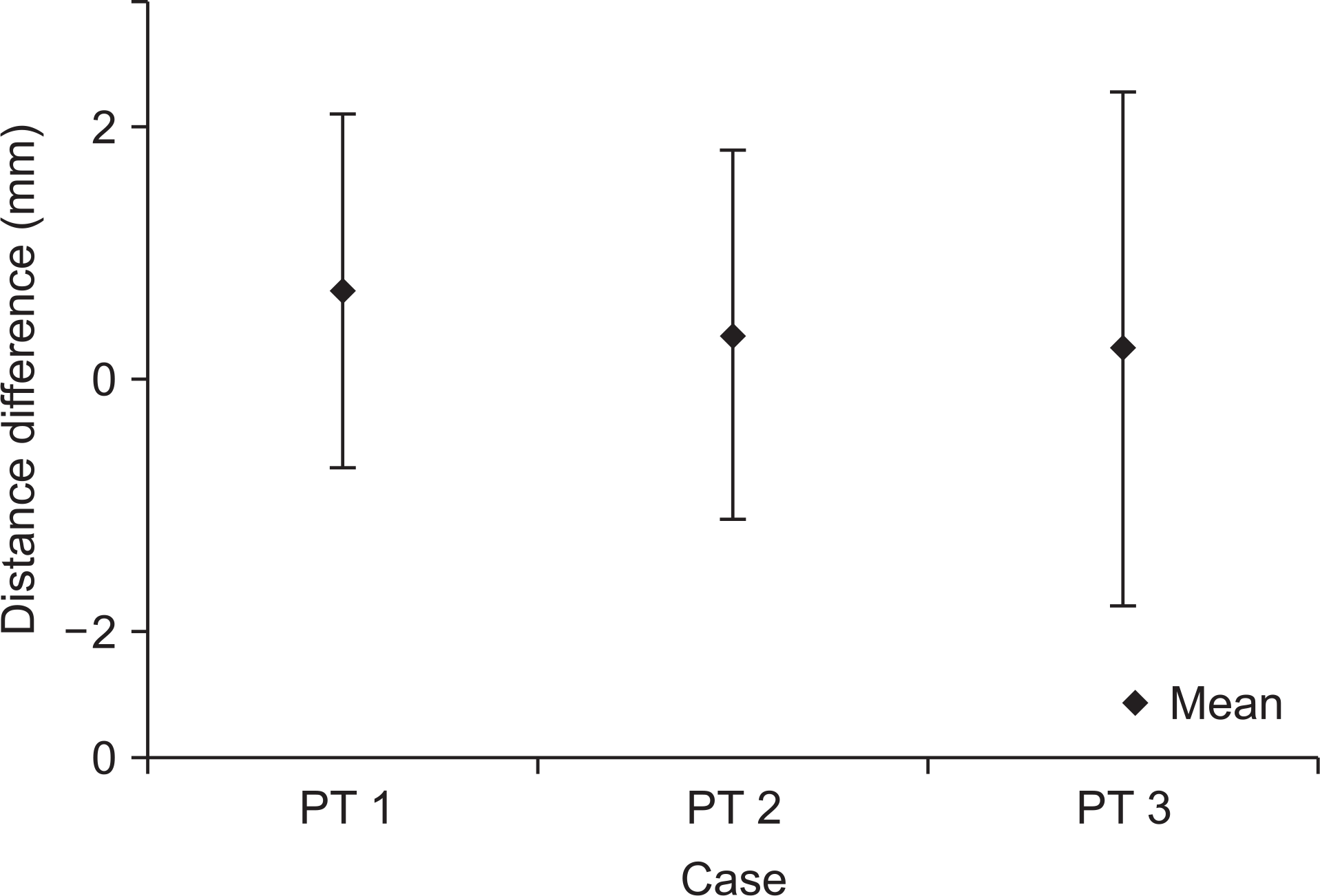
The result of the average difference in distance was within 1 mm and, as the worst case, the absolute difference did not exceed ±2 mm. The result of the geometric difference in the cross-section profile of each bolus was approximately 1 mm, which is a similar property of the average difference in distance. This discrepancy was negligible in affecting the dose reduction. The proposed fabrication of patient-specific bolus is useful for radiation therapy in the treatment of superficial regions, particularly those with an irregular shape.
Go to : 
REFERENCES
1.Vyas V., Palmer L., Mudge R., Jiang R., Fleck A., Schaly B, et al. On bolus for megavoltage photon and electron radiation therapy. Med Dosim. 2013. 38(3):268–73.

2.Hsu SH., Roberson PL., Chen Y., Marsh RB., Pierce LJ., Moran JM. Assessment of skin dose for breast chest wall radiotherapy as a function of bolus material. Phys Med Biol. 2008. 53(10):2593–606.

3.Butson MJ., Cheung T., Yu P., Metcalfe P. Effect on skin dose from unwanted air gaps under bolus in photon beam radiotherapy. Rad Meas. 2000. 32:201–4.
4.Kim SW., Shin HJ., Kay CS., Son SH. A customized bolus produced using a 3-dimensional printer for radiotherapy. PLoS One. 2014. 9(10):e110746.

5.Su S., Moran K., Robar JL. Design and production of 3D printed bolus for electron radiation therapy. J Appl Clin Med Phys. 2014. 15(4):4831.

6.Park SY., Choi CH., Park JM., Chun M., Han JH., Kim JI. A patient-specific polylactic acid bolus made by a 3D printer for breast cancer radiation therapy. PLoS One. 2016. 11(12):e0168063.

7.Ricotti R., Ciardo D., Pansini F., Bazani A., Comi S., Spoto R, et al. Dosimetric characterization of 3D printed bolus at different infill percentage for external photon beam radiotherapy. Phys Med. 2017. 39:25–32.

8.Zhao Y., Moran K., Yewondwossen M., Allan J., Clarke S., Ra-jaraman M, et al. Clinical applications of 3-dimensional printing in radiation therapy. Med Dosim. 2017. 42(2):150–5.

9.Robar JL., Moran K., Allan J., Clancey J., Joseph T., Chytyk-Praznik K, et al. Intrapatient study comparing 3D printed bolus versus standard vinyl gel sheet bolus for postmastectomy chest wall radiation therapy. Pract Radiat Oncol. 2018. 8(4):221–9.

Go to : 
 | Fig. 1(a) Transaxial view of patient CT and designed bolus and (b) volume rendering of designed bolus. |
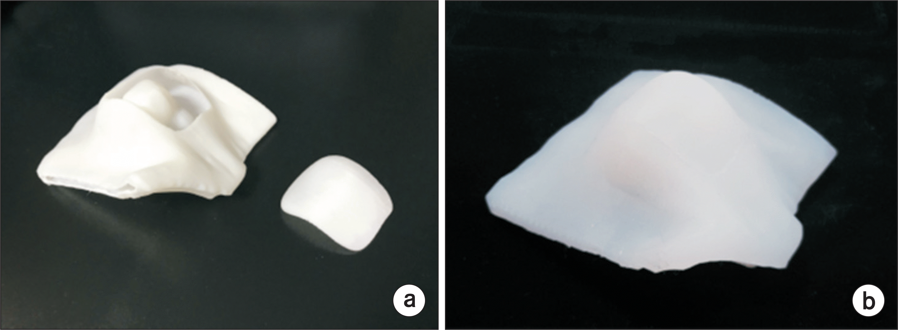 | Fig. 3(a) 3D printed bolus molds with body and lid part, and (b) produced patient-specific bolus. |
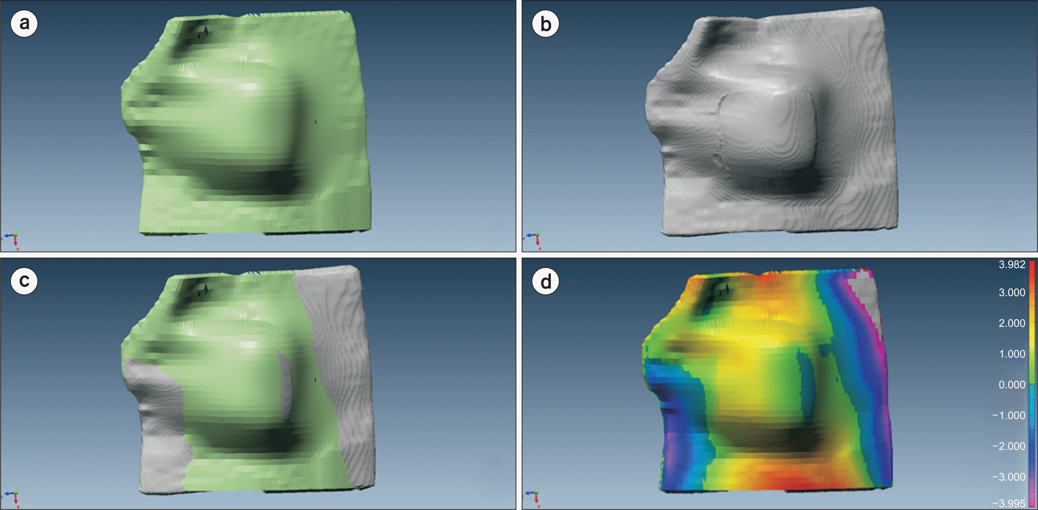 | Fig. 4(a) Planned bolus structure from TPS, (b) measured fabricated bolus structure, (c) superimposed structures after registration, and (d) color map of difference in distance between two structures. |
Table 1.
Physical property of Dragon SkinTM 10 MEDIUM and 3D printer settings.
Table 2.
3D modeling information for each structure.
| Patient 1 | Patient 2 | Patient 3 | ||||
|---|---|---|---|---|---|---|
| Planned | Fabricated | Planned | Fabricated | Planned | Fabricated | |
| Vertices | 62682 | 30866 | 29460 | 40088 | 163398 | 194514 |
| Facets | 125376 | 61728 | 58914 | 80218 | 326792 | 389009 |
Table 3.
Geometric difference of cross-section profile for each patient.
Table 4.
Comparison of volume and surface between planned and fabricated bolus.


 PDF
PDF ePub
ePub Citation
 Print
Print


 XML Download