

 PDF
PDF ePub
ePub Citation
 Print
Print


Introduction
Methods of evaluating the alveolar bone in the anterior mandible have been an object of study in a wide range of specialties in dentistry, including orthodontics, periodontics, and implant dentistry.123 Orthodontic labial movement of the tooth can result in alveolar bone dehiscence or fenestration, posing a risk of gingival recession and tooth loss.4 Therefore, knowledge of the extent of vertical and horizontal alveolar bone loss, as well as the topography of periodontal pockets, is important for accurate periodontal diagnosis and therapy.5 Dehiscence or a fenestration defect may also develop upon the placement of implants, thus requiring a bone evaluation.6
Periapical, bitewing, and panoramic radiographs are the radiographic methods most commonly used for diagnosing alveolar bone loss. However, these methods present limitations, such as image magnification, subjectivity in interpretation, 2-dimensional images of 3-dimensional structures, and reduced sensitivity in detecting changes at the levels of the facial and lingual bone crests and in detecting fenestration and alveolar bone dehiscence on the buccal and lingual side of alveolar bone.78 In the 1990s, the use of computed tomography (CT) and, shortly thereafter, the application of cone-beam computed tomography (CBCT) filled this void in radiographic diagnoses regarding the identification of the facial and lingual alveolar bones.39 However, a review of the literature showed that the methods used to measure the alveolar bone in the anterior mandible by means of CBCT images have not been described in an objective manner and have flaws in terms of reproducibility, which may compromise longitudinal studies.
Thus, the main challenge in radiographic studies intending to evaluate alveolar bone changes (resorption or regeneration) in the anterior mandible is to determine a stable reference that does not change in response to changes in the position of teeth due to occlusal forces, orthodontic treatment, or other dental treatments. For this reason, a reproducible and well-defined methodology must be established to evaluate bone plates. The purpose of this study, therefore, was to test the stability and reproducibility of a novel method of evaluating alveolar bone gain or loss and interdental septum changes in the anterior mandible based on CBCT images before and after orthodontic treatment.
Materials and Methods
This study was conducted after receiving approval from the local Ethics Committee on Human Research (CAAE: 30803614.3.0000.5137). Fifty-six CBCT images (28 pre-treatment, 28 post-treatment) of mandibular incisors were obtained from 28 dentate adult patients (22.9±4.1 years old) who presented with class I malocclusion and anterior dental crowding, and who had been referred for orthodontic treatment without extraction. Patients with gingival recession, periodontal disease, bone or soft tissue lesions in the mandibular incisor region, or no permanent mandibular incisors; patients who were smokers; and patients who used alcohol on a regular basis or who used medications that affected bone metabolism were excluded from this study.
The thickness and height of the alveolar bone and interdental septum were measured in CBCT images that had been obtained before orthodontic treatment and 3 months after the end of treatment. For CBCT scans, parameters were 80 kV, 10 mA, and 12 s of exposure, and the scans were acquired with 0.076-mm isotropic voxel size and a small field of view (FOV) (Kodak 9000 3D Cone Beam CT; East Kodak Company, Rochester, NY, USA). Linear and angular measurements from the CBCT images were obtained using the CS 3D Imaging software (Kodak Dental Systems, Rochester, NY, USA). The thickness and height of the alveolar bone and interdental septum were measured to the nearest 0.076 mm.
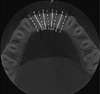
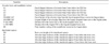
All of the alveolar bone measurements were performed in the parasagittal slices of the mandibular incisors that passed through the center of the mesial-distal width of the root, following the long dental axis. Measurements of the interdental septa were also performed in the parasagittal slices that passed through the center of the bone septum (Fig. 1). The benchmarks used in the present study and their definitions are presented in Table 1.
Tracing the lingual plane
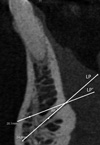
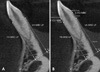
The lingual canal was chosen as the initial reference point to obtain the measurements of interest. First, the lingual foramen and the lingual canal were located. Next, a line was traced over the lingual canal, beginning at the lingual foramen and extending in the direction of the facial limit of the symphysis. In this study, this line traced over the lingual canal was referred to as the lingual plane (Fig. 2). After the lingual plane had been outlined in a tomographic section of the sagittal plane, the software enabled it to be viewed in all parasagittal sections.
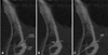
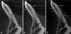
Two aspects must be considered when tracing the lingual plane: the ramification and the inclination of the lingual canal. According to Babiuc et al.,10 some patients (12.1%) have multiple canals; therefore, when many canals are present, one must consider the lingual canal to be that with the longest extension. As regards the trajectory of the lingual canal in the sagittal plane, some patients present a rather steep route. In such cases, a compensatory plane with a 20° reduction in the slope of the lingual plane should be traced in such a way as to intercept the lingual foramen and facilitate the measurement of the height of the bone plates (Fig. 3). This information must be recorded in the first measurement and repeated in the final measurement when evaluating the same structures of interest in longitudinal studies.
Tracing the triangle
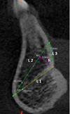
To test the reproducibility and the stability of the lingual plane between times T1 (pre-treatment) and T2 (post-treatment), a triangle was traced in the anterior region of the mandible in the median sagittal plane. The lingual plane constituted the first side of this triangle (L1). Next, a line was traced with a 20° slope from the facial extremity of the lingual plane, extending to the lingual limit of the symphysis (L2). A third line was traced, joining the lingual extremity of the 2 first lines (L3). To calculate the area of this triangle, the height of the triangle was traced (h) (Fig. 4).
Measurement of the height of the facial and lingual bone plates
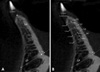
The measurements of the height of the facial and lingual bone plates were obtained in millimeters, beginning with the highest point of the marginal bone crest (MBC) and moving in the direction of the lingual plane in order to intercept the lingual plane perpendicularly. The measurements of these lines represented the facial height of the alveolar ridge from the facial MBC to the lingual plane (FH-MBC-LP) and the lingual height of the alveolar ridge from the lingual MBC to the lingual plane (LH-MBC-LP) (Fig. 5A). The distances between the lingual cementoenamel junction (CEJ) and the lingual MBC (L-CEJ-MBC) and between the facial CEJ and the facial MBC (F-CEJ-MBC) were also recorded (Fig. 5B).
Measurement of the thickness of the alveolar bone
First, in the parasagittal cut, the long axis of the mandibular incisor was traced from the pulp chamber ceiling to the lingual plane, following the center of the dental canal (mandibular incisor [MI] line) (Fig. 6A). Next, a line joining the facial and the lingual CEJ was drawn (CEJ-CEJ line). The measurements of the thickness of the alveolar bone thickness in the alveolar process were obtained in millimeters based on the lines traced parallel to the lingual plane, which were drawn beginning at the intersection between the MI and CEJ-CEJ lines, at points located 3, 6, 9, and 12 mm below the CEJ-CEJ line (Fig. 6B). In this manner, the thicknesses A1, A2, A3, and A4 were obtained, located 3, 6, 9, and 12 mm below the CEJ-CEJ line, respectively (Fig. 6C).
Measurement of the height and thickness of the interdental septum
The lingual plane can also be used as a reference to evaluate the interdental septum. Much like the alveolar bone region, here one can also measure the height and thickness of the interdental bone septum through the parasagittal plane.
To measure the height of the interdental septum, the sagittal tomography slice was placed in the center of the interdental space. Beginning at the highest point of the ridge—the bone crest—a line was drawn perpendicular to the lingual plane. Along this line, the distance was measured between the bone crest and the lingual plane, reaching the height of the interdental septum. This line was referred to as the bone crest height of the interdental septum (SH) (Fig. 7A).
The measurement of the thickness of the interdental septum used the SH line as the reference point. Beginning from the bone crest in the direction of the lingual plane, 4 points were marked to measure the thickness of the interdental ridge, at 3 mm, 6 mm, 9 mm, and 12 mm below the bone crest. Next, parallel lines were drawn to the lingual plane, passing through the 4 points cited above, which extended from the facial surface to the lingual surface of the septum in order to measure the thickness of the alveolar bone. Thus, the thicknesses S1, S2, S3, and S4 were obtained, located 3, 6, 9, and 12 mm below the bone crest, respectively (Fig. 7B).
Statistical analyses
Two observers—1 orthodontist and 1 oral radiologist—were calibrated. All measurements were taken twice, with a time interval of 1 week between each measurement. The intra-class correlation coefficient was used to determine intra- and inter-examiner agreement (ICC).11 The paired Student t-test was used to evaluate the area of the triangle, as well as the alveolar bone, mandibular incisor, and interdental septum measurements. Random error was quantified using the Dahlberg formula.12
Results
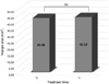
The area of the triangle was used to test the stability of the lingual plane. Intra- and inter-examiner agreement was excellent for the area of the triangle (0.9185 and 0.8606, respectively). The paired Student t-test showed no statistically significant difference among the measurements of the area of the triangle when times T1 and T2 were compared (P>0.05) (Fig. 8).
Intra- and inter-examiner agreement was also excellent for the alveolar bone and interdental septum measurements. For the alveolar bone, intra- and inter-examiner agreement was 0.9989 and 0.9977, respectively, while for the interdental septum the agreement values were 0.9987 and 0.9961, respectively (Table 2).
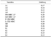
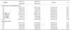
The random method error ranged from 0.13 to 0.29 for all variables (Table 3). Table 4 shows the mean and standard deviation of the alveolar bone, mandibular incisor, and interdental septum measurements, together with the results of the inter-examiner analysis. No statistically significant difference was found between the 2 examiners (P>0.05), showing the technical reliability of the measurements. Descriptive statistics also showed that the first and second variables of alveolar bone thickness (A1 and A2) were similar, with an increase in thickness as the most apical region was evaluated. The same pattern was observed for the variables S1 and S2 for the interdental septum.
Discussion
Orthodontic tooth movement can cause the root to brush up against the cortical bone, causing dehiscence and fenestration. In this context, it is important for orthodontists to observe the facial and lingual bone plates, mainly in adult patients, because they may also present some degree of alveolar bone loss before orthodontic treatment is started. CBCT is an imaging method that can access the lingual and facial aspects of dental roots without superposition of anatomic structures; however, a reproducible and well-defined methodology for measuring the alveolar bone plate on CBCT images has not yet been established. For this reason, this study sought to introduce a novel and reproducible method to evaluate the alveolar bone and interdental septum in the anterior mandible. The use of the lingual canal as a stable reference has not previously been investigated.
The first reference for the measurement of a structure is the starting point from which all other measurements will be performed and repeated. Thus, it is very important that this reference point can be localized in a precise and reproducible way to serve as a solid basis for future studies.13 Prior studies have utilized first reference points located in structures that can change with orthodontic treatment, such as the alveolar crest, the root apex, or the incisal and occlusal surface, or those that contain a complex system of localization, such as the coordinate system used to trace the mandibular plane; therefore, the use of these reference points has led to insufficient or variable replicability of the majority of findings.21415161718
The lingual canal presents distinct radiopaque walls, which are easily found in the median region of the mandible. The number of lingual foramina and canals can vary from patient to patient. In the findings of Babiuc et al.,10 71.9% of the analyzed cases presented a canal, while 28.1% of the cases presented more than 1 foramen and canal. In the present study, when multiple canals were found, the lingual canal proved to have a more extensive trajectory.
The lingual canal trajectory can also vary when observed in the sagittal plane. One tomographic study of the anatomy of the lingual canal reported that 62% of canals had a descending trajectory, 17.3% had an anterior trajectory, and 20.7% had an ascending trajectory.10 In the present study, all patients had a lingual canal with a descending trajectory; however, when the lingual canal trajectory was highly sloped (that is, heavily inclined in the vertical direction), a compensatory lingual plane was traced, beginning from the lingual foramen. We observed that the introduction of this stage did not reduce the reproducibility of the method, as it was necessary to record the number of degrees of compensation adopted in the first measurement of the CBCT images so that the examiner could replicate this measure in the line traced to highlight the compensatory lingual plane of the second measurement.
Prior studies have verified the need to evaluate the vertical movement of the lower incisors, in addition to the movements of rotation, translation, and proclination or retroclination of the incisor, in the analysis of vertical bone loss detected by the increase in the distance between the bone crest and the CEJ.119 With this new method, it is possible to register the vertical positioning of the incisors, allowing for the evaluation of vertical changes in the intrusion and extrusion of the mandibular incisors during orthodontic treatment. For this, it is only necessary to measure the distance from the pulp chamber ceiling to the lingual plane, through the line of the long dental axis (MI line).
The evaluation of the interdental septum compliments the analysis of the evaluation of the facial and lingual bone plates, since all of the alveolar walls must be evaluated as regards bone loss or gain. The intra- and inter-examiner agreement values obtained in this study were 0.9987 and 0.9961, respectively, showing excellent agreement. Hence, our results show that this method can also be used in research that seeks to evaluate bone height in the interdental region. Intra- and inter-examiner agreement for the evaluation of the alveolar bone was also excellent, confirming the excellent reproducibility of this method, which will be useful in transversal and longitudinal studies that seek to evaluate the bone anatomy of the mandibular incisor region.
The stability of the lingual plane between time points T1 and T2 was evaluated through the area of the triangle. There were no statistically significant differences among the measurements of the area of the triangle when time points T1 and T2 were compared (P>0.05), proving that the lingual plane did not change with orthodontic treatment. This finding may well have resulted from this anatomical structure being located in the basal bone (that is, below the dental roots), and thus not being affected by the orthodontic movement of the teeth. In contrast, vertical and horizontal changes in the symphysis during facial growth can occur;2021 therefore, we do not recommend the use of this methodology in patients who have not completed pubertal growth.
The Student t-test showed no statistically significant difference in the inter-examiner measurements, which proved to show adequate reproducibility in the measurement of the variables chosen for the study (P>0.05) (Table 4). The ICC values showing intra- and inter-examiner agreement were excellent for all variables, supporting the appropriateness of the method. Previous studies that evaluated the reliability of buccal bone height and thickness measurements from CBCT also showed high inter-rater reliability in measurements (0.76–0.99); however, the variables used had different reference points from the current study.2223
This study used a CBCT device with a relatively small voxel size and small FOV. When the bone thickness is similar to, or smaller than, the voxel size, the distance between the CEJ and the MBC can be overestimated; thus, decreasing the voxel size can improve the measurement accuracy.222425 Considering this limitation, we recommend that CBCT images be acquired on devices that use small voxels and a small FOV to better view the alveolar bone plates.
In conclusion, the method used in this study provides a valid and reproducible evaluation of the dimensions of the alveolar process in the anterior mandible using CBCT. This method can be used in cross-sectional studies and in longitudinal research seeking to evaluate changes in facial and lingual bone plates, vertical and angular changes of the mandibular incisors, and changes in the interdental septum by means of CBCT images. Thus, this can be a good measurement method for the anterior mandible for anthropologists, forensic experts, anatomists, orthodontists, and surgeons.

 XML Download