

 PDF
PDF ePub
ePub Citation
 Print
Print


Hip joint compression can reach up to 3–5 times body weight whilst walking or standing. Femoral neck fractures commonly have a high rate of fixation failure and complications including nonunion and posttraumatic avascular necrosis due to the associated anatomical structures.1) Therefore, in the absence of anatomical reduction and stable implants, the risk of complication rises considerably.
The Pauwels classification, which was introduced in 1935, is the first biomechanical classification for femoral neck fractures.2) This classification calculates the angle between the fracture line of the distal fragment and the horizontal line to determine shearing stress and compressive force.3) Furthermore, some clinical studies regarding femoral neck fractures have reported that an increased fracture angle is a predictor of postoperative complications.
In a vertical orientation femoral neck fracture, the fracture is subjected to greater shear forces rather than compression forces that are observed in more horizontally oriented fractures.4) Therefore, stable fixation of a Pauwels type III femoral neck fracture with an angle greater than 70° is often difficult to achieve.13) To overcome this difficulty, various implants including the dynamic hip screw (DHS) and blade type DHS (DHS-blade) have been used for fixation of this type of fracture.45678910111213)
Clinical comparisons of the different fixation methods have not been reported because Pauwels type III fractures are uncommon; however, various biomechanical tests have been performed to compare various fixation methods. The purpose of this systematic review was to investigate the various fixation methods or implants used in the treatment of Pauwels type III femoral neck fractures.
METHODS
A systematic review was performed according to the Preferred Reporting Items for Systematic Reviews and Meta-Analyses (PRISMA) guidelines.
Study Eligibility Criteria
Studies were selected based on the following inclusion criteria: (1) a biomechanical study of Pauwels type III femoral neck fracture and (2) the use of DHS fixation, multiple screw fixation or other devices for fixation of the fracture. Studies were excluded if they failed to meet the above criteria.
Search Methods for Identification of Studies
PubMed Central, OVID Medline, Cochrane Collaboration Library, Web of Science, Embase, and AHRQ databases were searched to identify relevant studies published up until August 2017 with English language restriction. The following search terms were used: “vertical femoral neck fracture,” “unstable femoral neck fracture,” “Pauwels femoral neck fracture,” “vertically oriented femoral neck fracture.” A manual search was also conducted with the aim of further identifying related references. Two investigators (JIY, YHC) independently reviewed titles, abstracts, and full texts of all potentially relevant studies as recommended by the Cochrane Collaboration.
Data Extraction
The following information was extracted from the included articles: authors, publication date, study design, number of subjects, fixation device, measurement device, and outcomes of biomechanical tests.
Methodological Quality Assessment
The Newcastle-Ottawa scale was used to assess methodological quality of nonrandomized studies. It contains eight items that are categorized into three dimensions: the selection of the study population, the comparability of the groups, and the ascertainment of the exposure (case-control study) or outcome (cohort study). Each dimension consists of subcategorized questions: selection (a maximum of four stars), comparability (a maximum of two stars), and exposure or outcome (a maximum of three stars). Thus, a study can be awarded a maximum of six stars, indicating the highest quality. Two of the authors (JIY, YHC) independently evaluated the quality of all the studies.
Go to : 
RESULTS
Search Results
The initial search identified 430 studies from the selected databases. However, 393 were excluded after screening of the abstracts and titles. The remaining 37 studies underwent full-text review. Twenty-two studies were further excluded. Details on the identification of relevant studies are shown in the flowchart of the study selection process (Fig. 1). Study design, number of subjects, fixation device material, osteotomy, and specimen position included in this study are summarized in Tables 1 and 2. Eight of these studies were performed using cadavers, six using sawbones, and the remaining one was a biomechanical study using a finite element model.
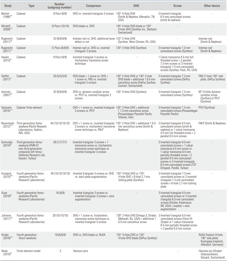
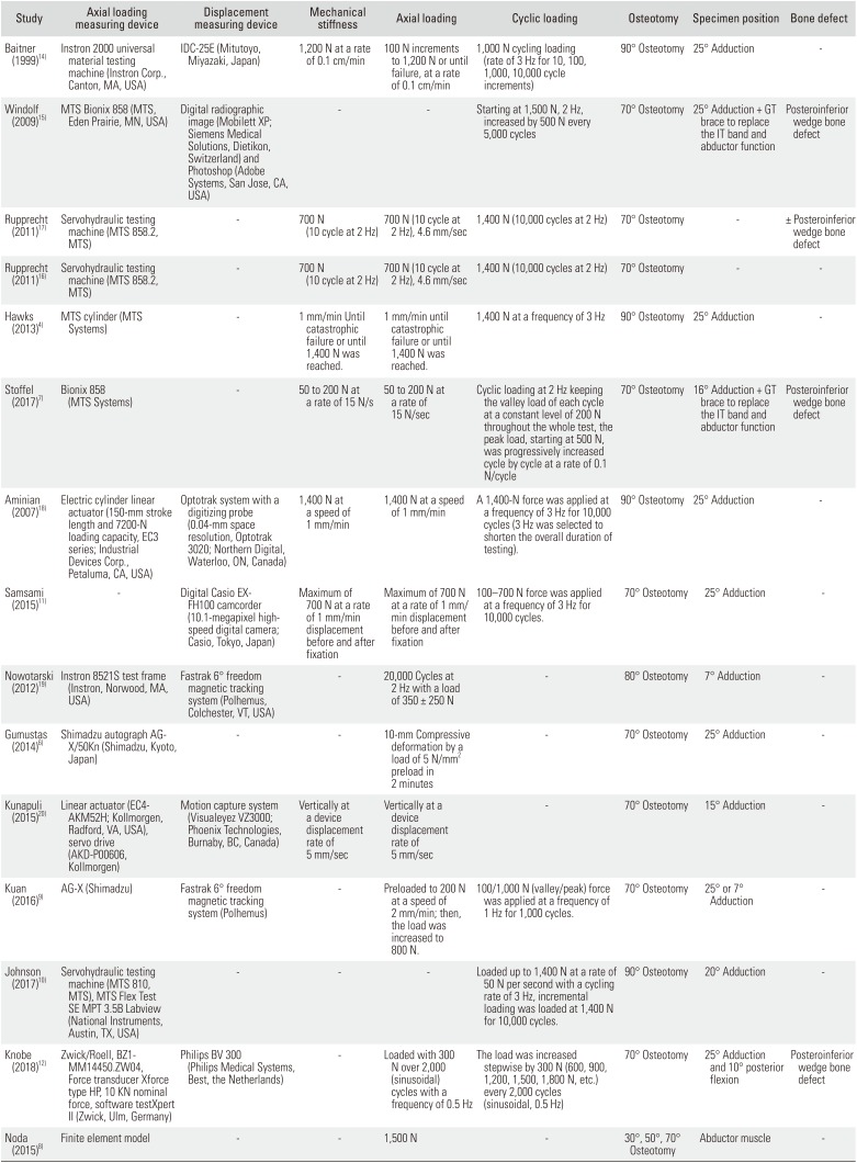
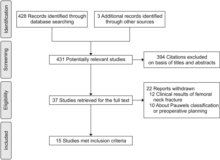
Table 1
Number and Type of Subjects and Fixation Device of Included Studies
| Study | Type | Number (subgroup number) | Comparison | DHS | Screw | Other device |
|---|---|---|---|---|---|---|
| Baitner (1999)14) | Cadaver | 8 Pairs (8/8) | DHS vs. inverted triangular 3 screws | 135° 4-Hole DHS (Smith & Nephew, Memphis, TN, USA) | 3 Inverted triangular 6.5-mm cannulated screws (smith & nephew) | - |
| Windolf (2009)15) | Cadaver | 10 Pairs (10/10) | DHS-blade vs. DHS | 135° 4-Hole DHS-blade or 135° 4-hole DHS (Synthes Inc., Bettlach, Switzerland) | - | - |
| Rupprecht (2011)16) | Cadaver | 32 (8/8/8/8) | Intertan nail vs. DHS, additional bone defect or not | 125° 2-Hole DHS (Synthes, West Chester, PA, USA) | - | Intertan nail (Smith & Nephew) |
| Rupprecht (2011)17) | Cadaver | 12 Pairs (8/8/8) | Intertan nail vs. DHS vs. inverted triangular 3 screws | 125° 2-Hole DHS (Synthes) | 3 Inverted triangular 7.3-mm cannulated screws (Synthes) | Intertan nail (Smith & Nephew) |
| Hawks (2013)4) | Cadaver | 9 Pairs (9/9) | Inverted triangular 3 screws vs. trochanteric transverse screw technique | - | 1 Calcar transverse 4.5-mm full threaded screw + 2 parallel 7.3-mm screws or 3 inverted triangular 7.3-mm cannulated screws (Synthes, Paoli, PA, USA) | - |
| Stoffel (2017)7) | Cadaver | 20 (5/5/5/5) | DHS-blade + 1 screw vs. DHS + 1 screw vs. FNS vs. inverted triangular 3 screws | 130° 2-Hole DHS or 130° 2-hole DHS-blade + additional 1 6.5-mm cancellous screw (DePuy Synthes, Zuchwil, Switzerland) | 3 Inverted triangular 7.3-mm cannulated screws (DePuy Synthes) | FNS (1-hole 130° side plate; DePuy Synthes) |
| Aminian (2007)18) | Cadaver | (8/8/8/8) | DHS vs. dynamic condylar screw vs. PFLP vs. inverted triangular 3 screws | 135° 4-Hole DHS (Synthes) | 3 Inverted triangular 7.3-mm cannulated screws (Synthes) | 95° 6-Hole dynamic condylar screw (Synthes) or PFLP (Synthes) |
| Samsami (2015)11) | Cadaver finite element | 3 | DHS + 1 screw vs. inverted triangular 3 screws vs. PFLP | 135° 3-Hole DHS + additional 1 7.3-mm cancellous screw (Pooyandegan Pezeshki Pardis, Teheran, Iran) | 3 Inverted triangular 7.3-mm cannulated screws (Pooyandegan Pezeshki Pardis) | PFLP (Synthes) |
| Nowotarski (2012)19) | Third generation femur sawbone (Pacific Research Laboratories, Vashon, WA, USA) | 40 (10/10/10/10) | DHS + 1 screw vs. inverted triangular 3 screws vs. trochanteric transverse screw technique vs. FNLP | 135° 2-Hole DHS + additional 1 6.5- mm cancellous screw (Smith & Nephew) | 3 Inverted triangular 6.5-mm cannulated screws (smith & nephew) or 1 calcar transverse 4.5-mm full threaded screw + 2 parallel 6.5-mm screws | FNLP (Smith & Nephew) |
| Gumustas (2014)6) | Third generation femur sawbone (FMR-01 new third generation composite left femur; Selbones Research Lab., Kayseri, Turkey) | 28 (7/7/7/7) | Inverted triangular 3 screws + 1 transverse screw vs. trochanteric transverse screw technique vs. inverted triangular 3 screws | - | 3 Inverted triangular 6.5-mm cannulated screws + 1 calcar transverse 6.5-mm screw or 1 calcar transverse 6.5-mm partially threaded screw + 2 parallel 6.5-mm cannulated screws or 3 inverted triangular 6.5-mm cannulated screws (TST Ortopedi, Pendik, Turkey) | - |
| Kunapuli (2015)20) | Fourth generation femur sawbone (Pacific Research Laboratories) | 40 (10/10/10/10) | Inverted triangular 3 screws vs. DHS vs. each plate augmentation | 135° 4-Hole DHS or 135° 4-hole DHS + 6-hole 2.7-mm locking plate (Synthes) | 3 Inverted triangular 7.3-mm cannulated screws or 3 inverted triangular 7.3-mm cannulated screws + 6-hole 2.7-mm locking plate | - |
| Kuan (2016)9) | Fourth generation femur sawbone (Pacific Research Laboratories) | 16 (8/8) | Inverted triangular 3 screws vs. inverted triangular 3 screws + wire augmentation | - | 3 Inverted triangular 6.5-mm cannulated screws or 3 inverted triangular 6.5-mm cannulated screws (Stryker, Kalamazoo, MI, USA) + washer + wire augmentation | - |
| Johnson (2017)10) | Fourth generation femur sawbone (Pacific Research Laboratories) | 30 (10/10/10) | DHS + 1 screw vs. trochanteric transverse screw technique vs. inverted triangular 3 screws | 130° 2-Hole DHS (Omega 3; Stryker, Mahwah, NJ, USA) + additional 1 6.5-mm cancellous screw | 3 Inverted triangular 6.5-mm cannulated screws (Asnis III; Stryker or 1 calcar transverse 6.5-mm partially threaded screw + 2 parallel 6.5-mm screws | - |
| Knobe (2018)12) | Fourth generation femur sawbone | 18 (6/6/6) | DHS vs. DHS-blade vs. RoSA | 135° 4-Hole DHS or 135° 4-hole DHS-blade (DePuy Synthes) | - | RoSA fixation (3-hole 136° side plate; Koenigsee Implants, Allendorf, Germany) |
| Noda (2015)8) | Finite element model | 3 | Hansson pins | - | Hansson pin (Stryker Osteosynthesis, Selzach, Switzerland) |
![]()
Table 2
Experimental Setting of Included Studies
| Study | Axial loading measuring device | Displacement measuring device | Mechanical stiffness | Axial loading | Cyclic loading | Osteotomy | Specimen position | Bone defect |
|---|---|---|---|---|---|---|---|---|
| Baitner (1999)14) | Instron 2000 universal material testing machine (Instron Corp., Canton, MA, USA) | IDC-25E (Mitutoyo, Miyazaki, Japan) | 1,200 N at a rate of 0.1 cm/min | 100 N increments to 1,200 N or until failure, at a rate of 0.1 cm/min | 1,000 N cycling loading (rate of 3 Hz for 10, 100, 1,000, 10,000 cycle increments) | 90° Osteotomy | 25° Adduction | - |
| Windolf (2009)15) | MTS Bionix 858 (MTS, Eden Prairie, MN, USA) | Digital radiographic image (Mobilett XP; Siemens Medical Solutions, Dietikon, Switzerland) and Photoshop (Adobe Systems, San Jose, CA, USA) | - | - | Starting at 1,500 N, 2 Hz, increased by 500 N every 5,000 cycles | 70° Osteotomy | 25° Adduction + GT brace to replace the IT band and abductor function | Posteroinferior wedge bone defect |
| Rupprecht (2011)17) | Servohydraulic testing machine (MTS 858.2, MTS) | - | 700 N (10 cycle at 2 Hz) | 700 N (10 cycle at 2 Hz), 4.6 mm/sec | 1,400 N (10,000 cycles at 2 Hz) | 70° Osteotomy | - | ± Posteroinferior wedge bone defect |
| Rupprecht (2011)16) | Servohydraulic testing machine (MTS 858.2, MTS) | - | 700 N (10 cycle at 2 Hz) | 700 N (10 cycle at 2 Hz), 4.6 mm/sec | 1,400 N (10,000 cycles at 2 Hz) | 70° Osteotomy | - | - |
| Hawks (2013)4) | MTS cylinder (MTS Systems) | - | 1 mm/min Until catastrophic failure or until 1,400 N was reached. | 1 mm/min until catastrophic failure or until 1,400 N was reached. | 1,400 N at a frequency of 3 Hz | 90° Osteotomy | 25° Adduction | - |
| Stoffel (2017)7) | Bionix 858 (MTS Systems) | - | 50 to 200 N at a rate of 15 N/s | 50 to 200 N at a rate of 15 N/sec | Cyclic loading at 2 Hz keeping the valley load of each cycle at a constant level of 200 N throughout the whole test, the peak load, starting at 500 N, was progressively increased cycle by cycle at a rate of 0.1 N/cycle | 70° Osteotomy | 16° Adduction + GT brace to replace the IT band and abductor function | Posteroinferior wedge bone defect |
| Aminian (2007)18) | Electric cylinder linear actuator (150-mm stroke length and 7200-N loading capacity, EC3 series; Industrial Devices Corp., Petaluma, CA, USA) | Optotrak system with a digitizing probe (0.04-mm space resolution, Optotrak 3020; Northern Digital, Waterloo, ON, Canada) | 1,400 N at a speed of 1 mm/min | 1,400 N at a speed of 1 mm/min | A 1,400-N force was applied at a frequency of 3 Hz for 10,000 cycles (3 Hz was selected to shorten the overall duration of testing). | 90° Osteotomy | 25° Adduction | - |
| Samsami (2015)11) | - | Digital Casio EXFH100 camcorder (10.1-megapixel highspeed digital camera; Casio, Tokyo, Japan) | Maximum of 700 N at a rate of 1 mm/min displacement before and after fixation | Maximum of 700 N at a rate of 1 mm/ min displacement before and after fixation | 100–700 N force was applied at a frequency of 3 Hz for 10,000 cycles. | 70° Osteotomy | 25° Adduction | - |
| Nowotarski (2012)19) | Instron 8521S test frame (Instron, Norwood, MA, USA) | Fastrak 6° freedom magnetic tracking system (Polhemus, Colchester, VT, USA) | - | 20,000 Cycles at 2 Hz with a load of 350 ± 250 N | - | 80° Osteotomy | 7° Adduction | - |
| Gumustas (2014)6) | Shimadzu autograph AGX/50Kn (Shimadzu, Kyoto, Japan) | - | - | 10-mm Compressive deformation by a load of 5 N/mm2 preload in 2 minutes | - | 70° Osteotomy | 25° Adduction | - |
| Kunapuli (2015)20) | Linear actuator (EC4-AKM52H; Kollmorgen, Radford, VA, USA), servo drive (AKD-P00606, Kollmorgen) | Motion capture system (Visualeyez VZ3000; Phoenix Technologies, Burnaby, BC, Canada) | Vertically at a device displacement rate of 5 mm/sec | Vertically at a device displacement rate of 5 mm/sec | - | 70° Osteotomy | 15° Adduction | - |
| Kuan (2016)9) | AG-X (Shimadzu) | Fastrak 6° freedom magnetic tracking system (Polhemus) | - | Preloaded to 200 N at a speed of 2 mm/min; then, the load was increased to 800 N. | 100/1,000 N (valley/peak) force was applied at a frequency of 1 Hz for 1,000 cycles. | 70° Osteotomy | 25° or 7° Adduction | - |
| Johnson (2017)10) | Servohydraulic testing machine (MTS 810, MTS), MTS Flex Test SE MPT 3.5B Labview (National Instruments, Austin, TX, USA) | - | - | - | Loaded up to 1,400 N at a rate of 50 N per second with a cycling rate of 3 Hz, incremental loading was loaded at 1,400 N for 10,000 cycles. | 90° Osteotomy | 20° Adduction | - |
| Knobe (2018)12) | Zwick/Roell, BZ1-MM14450.ZW04, Force transducer Xforce type HP, 10 KN nominal force, software testXpert II (Zwick, Ulm, Germany) | Philips BV 300 (Philips Medical Systems, Best, the Netherlands) | - | Loaded with 300 N over 2,000 (sinusoidal) cycles with a frequency of 0.5 Hz | The load was increased stepwise by 300 N (600, 900, 1,200, 1,500, 1,800 N, etc.) every 2,000 cycles (sinusoidal, 0.5 Hz) | 70° Osteotomy 25° Adduction and 10° posterior flexion | Posteroinferior wedge bone defect | - |
| Noda (2015)8) | Finite element model | - | - | 1,500 N | - | 30°, 50°, 70° Osteotomy | Abductor muscle | - |
![]()
Load-to-Failure and Axial Stiffness Using Cadavers
In one study,14) under vertical loading at 25° adduction, the mean load-to-failure of the 135° four-hole DHS group was significantly higher than that of the three inverted triangular 6.5-mm cannulated screw fixation group (p < 0.01). In a study of Rupprecht et al.,17) the mean load-to-failure of the Intertan nail group (4,929 ± 419 N) was significantly higher than that of the DHS group (3,505 ± 453 N, p = 0.036). However, there was no significant difference in the force the femur could tolerate between the two groups in the presence of a bone defect (Intertan nail with bone defect, 3,998 ± 418 N vs. DHS with bone defect, 3,785 ± 822 N; p = 0.773). In addition, it was noted that the femur was damaged by less force when a bone defect was present; however, there was no statistically significant difference depending on the presence/absence of a bone defect (p = 0.175) (Table 3).
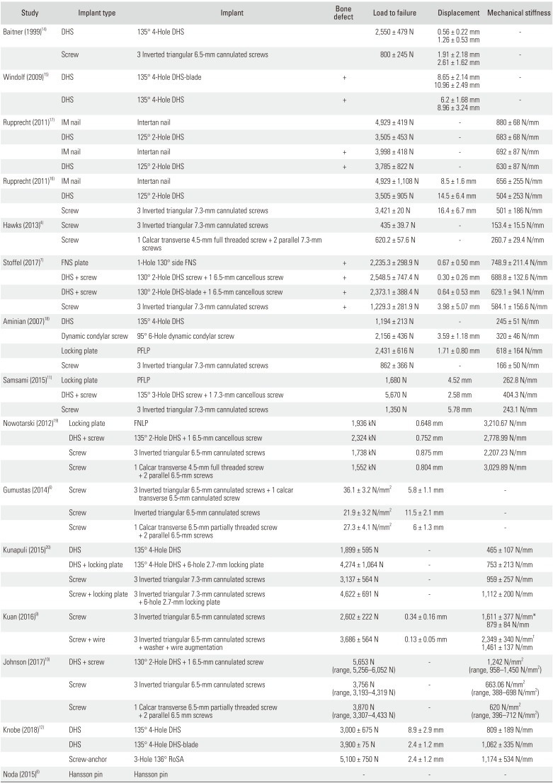
Table 3
Stiffness, Axial Loading, and Cyclic Loading Results
| Study | Implant type | Implant | Bone defect | Load to failure | Displacement | Mechanical stiffness |
|---|---|---|---|---|---|---|
| Baitner (1999)14) | DHS | 135° 4-Hole DHS | 2,550 ± 479 N | 0.56 ± 0.22 mm | - | |
| 1.26 ± 0.53 mm | ||||||
| Screw | 3 Inverted triangular 6.5-mm cannulated screws | 800 ± 245 N | 1.91 ± 2.18 mm | - | ||
| 2.61 ± 1.62 mm | ||||||
| Windolf (2009)15) | DHS | 135° 4-Hole DHS-blade | + | 8.65 ± 2.14 mm | - | |
| 10.96 ± 2.49 mm | ||||||
| DHS | 135° 4-Hole DHS | + | 6.2 ± 1.68 mm | - | ||
| 8.96 ± 3.24 mm | ||||||
| Rupprecht (2011)17) | IM nail | Intertan nail | 4,929 ± 419 N | - | 880 ± 68 N/mm | |
| DHS | 125° 2-Hole | DHS | 3,505 ± 453 N | - | 683 ± 68 N/mm | |
| IM nail | Intertan nail | + | 3,998 ± 418 N | - | 692 ± 87 N/mm | |
| DHS | 125° 2-Hole DHS | + | 3,785 ± 822 N | - | 630 ± 87 N/mm | |
| Rupprecht (2011)16) | IM nail | Intertan nail | 4,929 ± 1,108 N | 8.5 ± 1.6 mm | 656 ± 255 N/mm | |
| DHS | 125° 2-Hole DHS | 3,505 ± 905 N | 14.5 ± 6.4 mm | 504 ± 253 N/mm | ||
| Screw | 3 Inverted triangular 7.3-mm cannulated screws | 3,421 ± 20 N | 16.4 ± 6.7 mm | 501 ± 186 N/mm | ||
| Hawks (2013)4) | Screw | 3 Inverted triangular 7.3-mm cannulated screws | 435 ± 39.7 N | - | 153.4 ± 15.5 N/mm | |
| Screw | 1 Calcar transverse 4.5-mm full threaded screw + 2 parallel 7.3-mm screws | 620.2 ± 57.6 N | - | 260.7 ± 29.4 N/mm | ||
| Stoffel (2017)7) | FNS plate | 1-Hole 130° side FNS | + | 2,235.3 ± 298.9 N | 0.67 ± 0.50 mm | 748.9 ± 211.4 N/mm |
| DHS + screw 130° | 2-Hole DHS screw + 1 6.5-mm cancellous screw | + | 2,548.5 ± 747.4 N | 0.30 ± 0.26 mm | 688.8 ± 132.6 N/mm | |
| DHS + screw 130° | 2-Hole DHS-blade + 1 6.5-mm cancellous screw | + | 2,373.1 ± 388.4 N | 0.64 ± 0.53 mm | 629.1 ± 94.1 N/mm | |
| Screw | 3 Inverted triangular 7.3-mm cannulated screws | + | 1,229.3 ± 281.9 N | 3.98 ± 5.07 mm | 584.1 ± 156.6 N/mm | |
| Aminian (2007)18) | DHS | 135° 4-Hole DHS | 1,194 ± 213 N | - | 245 ± 51 N/mm | |
| Dynamic condylar screw | 95° 6-Hole dynamic condylar screw | 2,156 ± 436 N | 3.59 ± 1.18 mm | 320 ± 46 N/mm | ||
| Locking plate | PFLP | 2,431 ± 616 N | 1.71 ± 0.80 mm | 618 ± 164 N/mm | ||
| Screw | 3 Inverted triangular 7.3-mm cannulated screws | 862 ± 366 N | - | 166 ± 50 N/mm | ||
| Samsami (2015)11) | Locking plate | PFLP | 1,680 N | 4.52 mm | 262.8 N/mm | |
| DHS + screw | 135° 3-Hole DHS screw + 1 7.3-mm cancellous screw | 5,670 N | 2.58 mm | 404.3 N/mm | ||
| Screw | 3 Inverted triangular 7.3-mm cannulated screws | 1,350 N | 5.78 mm | 243.1 N/mm | ||
| Nowotarski (2012)19) | Locking plate | FNLP | 1,936 kN | 0.648 mm | 3,210.67 N/mm | |
| DHS + screw | 135° 2-Hole DHS + 1 6.5-mm cancellous screw | 2,324 kN | 0.752 mm | 2,778.99 N/mm | ||
| Screw | 3 Inverted triangular 6.5-mm cannulated screws | 1,738 kN | 0.875 mm | 2,207.23 N/mm | ||
| Screw | 1 Calcar transverse 4.5-mm full threaded screw + 2 parallel 6.5-mm screws | 1,552 kN | 0.804 mm | 3,029.89 N/mm | ||
| Gumustas (2014)6) | Screw | 3 Inverted triangular 6.5-mm cannulated screws + 1 calcar transverse 6.5-mm cannulated screw | 36.1 ± 3.2 N/mm2 | 5.8 ± 1.1 mm | - | |
| Screw | Inverted triangular 6.5-mm cannulated screws | 21.9 ± 3.2 N/mm2 | 11.5 ± 2.1 mm | - | ||
| Screw | 1 Calcar transverse 6.5-mm partially threaded screw + 2 parallel 6.5-mm screws | 27.3 ± 4.1 N/mm2 | 6 ± 1.3 mm | - | ||
| Kunapuli (2015)20) | DHS | 135° 4-Hole DHS | 1,899 ± 595 N | - | 465 ± 107 N/mm | |
| DHS + locking plate | 135° 4-Hole DHS + 6-hole 2.7-mm locking plate | 4,274 ± 1,064 N | - | 753 ± 213 N/mm | ||
| Screw | 3 Inverted triangular 7.3-mm cannulated screws | 3,137 ± 564 N | - | 959 ± 257 N/mm | ||
| Screw + locking plate | 3 Inverted triangular 7.3-mm cannulated screws + 6-hole 2.7-mm locking plate | 4,622 ± 691 N | - | 1,112 ± 200 N/mm | ||
| Kuan (2016)9) | Screw | 3 Inverted triangular 6.5-mm cannulated screws | 2,602 ± 222 N | 0.34 ± 0.16 mm | 1,611 ± 377 N/mm* | |
| 879 ± 84 N/mm | ||||||
| Screw + wire | 3 Inverted triangular 6.5-mm cannulated screws + washer + wire augmentation | 3,686 ± 564 N | 0.13 ± 0.05 mm | 2,349 ± 340 N/mm† | ||
| 1,461 ± 137 N/mm | ||||||
| Johnson (2017)10) | DHS + screw | 130° 2-Hole DHS + 1 6.5-mm cannulated screw | 5,653 N (range, 5,256–6,052 N) | - | 1,242 N/mm2 (range, 958–1,450 N/mm2) | |
| Screw | 3 Inverted triangular 6.5-mm cannulated screws | 3,756 N (range, 3,193–4,319 N) | - | 663.06 N/mm2 (range, 388–698 N/mm2) | ||
| Screw | 1 Calcar transverse 6.5-mm partially threaded screw + 2 parallel 6.5 mm screws | 3,870 N (range, 3,307–4,433 N) | - | 620 N/mm2 (range, 396–712 N/mm2) | ||
| Knobe (2018)12) | DHS | 135° 4-Hole DHS | 3,000 ± 675 N | 8.9 ± 2.9 mm | 809 ± 189 N/mm | |
| DHS | 135° 4-Hole DHS-blade | 3,900 ± 75 N | 2.4 ± 1.2 mm | 1,062 ± 335 N/mm | ||
| Screw-anchor | 3-Hole 136° RoSA | 5,100 ± 750 N | 2.4 ± 1.2 mm | 1,174 ± 534 N/mm | ||
| Noda (2015)8) | Hansson pin | Hansson pin | - | - | - |
![]()
In another study by Rupprecht et al.,16) it was revealed that the Intertan nails (4,929 ± 1,105 N) had statistically significantly higher load-to-failure compared to the DHS (3,505 ± 905 N, p < 0.05). In the study, only two failure tests were performed using the three inverted triangular 7.3-mm cannulated screws as many injuries had occurred in previous experiments: the mean load-to-failure of the screws was 3,421 ± 20 N, and statistical analysis was not performed for this result. Hawks et al.4) measured the force required to cause 3 mm of vertical displacement: 43% more force was required when using one calcar transtransverse 4.5-mm full threaded screw and two parallel 7.3-mm screws (mean force, 620.2 ± 57.6 N; range, 488.5 to 998.6 N) than when using the three inverted triangular 7.3-mm cannulated screws (mean force, 435.0 ± 39.7 N; range, 214.9 to 591.1 N; p = 0.018). Mechanical stiffness was 70% higher in the one calcar transverse 4.5-mm full threaded screw with two additional parallel 7.3-mm screw group (mean stiffness, 260.7 ± 29.4 N/mm; range, 175.7 to 440.3 N/mm) than the inverted triangular screw group (mean stiffness, 153.4 ± 15.5 N/mm; range, 65.4 to 202.4 N/mm; p = 0.026).
In a study by Stoffel et al.,7) the mean axial stiffness was 688.8 ± 132.6 N/mm for the DHS group, 629.1 ± 94.1 N/mm for the DHS-blade group, 748.9 ± 211.4 N/mm for the femoral neck system (FNS) group and 584.1 ± 156.6 N/mm (p = 0.067) for the cannulated screw fixation. The mean number of cycles for the onset of construct failure was 20,485 ± 7,474 for the DHS group, 18,731 ± 3,884 for the DHS-blade group, 17,353 ± 2,989 for the FNS group, and 7,293 ± 2,819 for the cannulated screw group. Furthermore, the follow-up load-to-failure value was 2,548.5 ± 747.4 N for the DHS group, 2,373.1 ± 388.4 N for the DHS-blade group, 2,235.3 ± 298.9 N for the FNS group, and 1,229.3 ± 281.9 N for the cannulated screw group. The results showed that the DHS, DHS-blade, and FNS groups had significantly higher values than the cannulated screw group (p < 0.001). The FNS group showed failure strength comparable to that of the DHS group, both of which were superior to that of the cannulated screw group in cyclic loading and axial stiffness.
In a study by Aminian et al.,18) all eight specimens in the cannulated screw group failed during incremental loading. In the DHS group, five of eight specimens failed with incremental loading, and three failed with cyclical testing. The three specimens that survived incremental loading had the highest bone density measurements. The three surviving specimens failed at cycle number 1,087, 1,822, and 7,450. The combined 16 specimens in the dynamic condylar screw group and proximal femoral locking plate (PFLP) group survived both incremental and cyclical loading. The PFLP group demonstrated the greatest stiffness (p < 0.05). Stiffness values in the dynamic condylar screw group and DHS group were statistically equivalent, whereas the cannulated screw was the weakest construct. The PFLP group and dynamic condylar screw group failed at higher loads than the DHS group and cannulated screw group (p < 0.05).
Samsami et al.11) reported that the stiffness, relative stiffness, failure load, and failure energy for 135° three-hole DHS with one 7.3-mm cancellous screw were approximately higher by 54%, 78%, 236% and 706%, respectively, than those for the PFLP, and the axial femoral head displacement for this method was 43% lower than that for the PFLP. Moreover, the biomechanical parameters of the 135° three-hole DHS with one 7.3-mm cancellous screw method (stiffness, relative stiffness, failure load, and failure energy) were higher by about 66%, 105%, 320%, and 515%, respectively, than those for three inverted triangular 7.3-mm cannulated screw fixation, and the axial femoral head displacement of this technique was 55% lower than that of the cannulated screws.
Load-to-Failure and Axial Stiffness Using Sawbones
One study19) reported that the mean axial stiffness in the femoral neck locking plate (FNLP) group (3,210.67 N/mm) was significantly higher than that in the other groups. However, the highest destructive failure load was observed in the 135° two-hole DHS with one 6.5-mm cancellous screw group. In other study,6) the average maximum strength measured in three inverted triangular 6.5-mm cannulated screws with one calcar transverse 6.5-mm cannulated screw group was significantly higher than that in other groups (p < 0.001 for all groups) (Table 3).
Kunapuli et al.20) reported that failure loads were not related to the use of plates in the two screw groups (p = 0.11). However, the group using cannulated screws or DHS fixation with locking plate augmentation showed an 83% increase in the failure rate compared to the group without locking plate augmentation (2,409 vs. 4,417 N, p < 0.01). Furthermore, the screw group showed 26% higher load-to-failure than the DHS group (3,879 vs. 3,087 N, p < 0.01). In a study by Kuan et al.,9) the axial stiffness at the 7° (p < 0.001) and 25° (p < 0.001) valgus positions was significantly higher in the wire augmentation group. In addition, the mean load-to-failure was significantly higher in the wire augmentation group (3,686 ± 564 N) than in the non-treated group (2,602 ± 222 N, p < 0.001).
Johnson et al.10) reported that the group utilizing one calcar transverse 6.5-mm partially threaded screw with two parallel 6.5-mm screws showed an average maximum failure load of 3,870 N. In comparison, the group using the three inverted triangular 6.5-mm screws had an average maximum failure load of 3,756 N (p = 0.7669). In the 130° DHS and two-hole side plate with one 6.5-mm cannulated screw group, the average maximum failure load was significantly higher than that in the other groups. In a study by Knobe et al.,12) the average failure load of the rotationally stable screw-anchor (RoSA) system was 5,100 ± 750 N, whereas that for the 135° four-hole DHS was 3,000 ± 675 N and that for the 135° four-hole DHS-blade was 3,900 ± 75 N (p = 0.002). Noda et al.8) measured the stress applied to the medical femoral neck according to Pauwels type when vertical loading was applied. The highest stress was observed in type III.
Displacement
In a study by Baitner et al.,14) displacement of the femoral head upon axial loading (500 N) and the superior and inferior distance from the osteotomy site were measured. The superior and inferior distance from the osteotomy site was 0.56 ± 0.22 mm and 1.26 ± 0.53 mm, respectively, in the 135° four-hole DHS group and 1.91 ± 2.18 mm and 2.61 ± 1.62 mm, respectively, in the group using the three inverted triangular 6.5-mm cannulated screws. The authors reported that the displacement of the femoral head in the 135° four-hole DHS group was shorter.
In a study by Windolf et al.,15) the incidence of more than 0.5 mm displacement was 50% (five cases) in the 135° four-hole DHS-blade group and 100% (10 cases) in 135° four-hole DHS group. After 200 cycles of loading, the displacement distance was 8.65 ± 2.14 mm in the 135° four-hole DHS-blade group, and 6.2 ± 1.68 mm in the 135° four-hole DHS group (p = 0.004). After 10,000 cycles of loading, the displacement distance was 10.96 ± 2.49 mm in the 135° four-hole DHS-blade group and 8.96 ± 3.24 mm in the 135° four-hole DHS group (p = 0.026). As a result, the 135° four-hole DHS-blade group was less displaced than the 135° four-hole DHS group; however, the displacement distance in the DHS-blade group was longer than that in the DHS group.
In one study17) performed with a loading of 700 N (250 cycles), displacement was 14.5 ± 2.2 mm in the 125° two-hole DHS group; displacement of the Intertan group was 8.5 ± 0.5 mm, which was significantly shorter than that of the DHS group (p = 0.007). In a study by Rupprecht et al.,16) with axial loading of 700 N (250 cycles), displacement was the least in the Intertan group and there was no difference between the other two groups. Samsami et al.11) reported that the displacement in a 135° three-hole DHS with an additional 7.3-mm cancellous screw group, PFLP group and, a three inverted triangular 7.3-mm cannulated screw group was 2.58 mm, 4.52 mm, and 5.78 mm, respectively. They recommended the 135° three-hole DHS with an additional 7.3-mm cancellous screw fixation was a better method.
In a study by Nowotarski,19) cyclic displacement (20,000 cycles at 2 Hz with a load of 350 ± 250 N) in the FNLP group was the smallest in comparison with the other groups. In a study by Gumustas et al.,6) the average relocation in the line osteotomy at the moment of average maximum strength (21.9 ± 3.2 N/mm2) was the least in the three inverted triangular 6.5-mm cannulated screw with one 6.5-mm transverse calcar screw group showing statistically significant difference (p < 0.05).
In one study, after 5,000 loading cycles, the average migration of implant position was the smallest in the 130° two-hole DHS with additional 6.5-mm cancellous screw group. The displacement observed in the inverted triangular 7.3-mm cannulated screw group was significantly higher than that of the other groups (p = 0.036). However, there was no statistically significant difference in displacement between different implants.
In a study by Kuan et al.,9) cyclic displacement in the wire augmentation group (0.34 ± 0.16 mm) was statistically significantly smaller than that in the group without wire augmentation (0.13 ± 0.05 mm) (p < 0.001). In one study, the displacement after loading (1,800 N) in the 135° four-hole DHS group, 135° four-hole DHS-blade group, and RoSA group was 8.9 ± 2.9 mm, 2.4 ± 1.2 mm, and 2.4 ± 1.2 mm, respectively (p = 0.001) (Table 3).
Risk of Bias
The Newcastle-Ottawa scale was used to assess the quality of the selected studies. All included studies scored 6–8 points, indicating relatively high quality (Table 4).
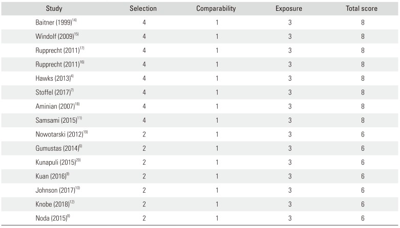
Table 4
Quality Assessment of the Included Studies by the Newcastle-Ottawa Scale
| Study | Selection | Comparability | Exposure | Total score |
|---|---|---|---|---|
| Baitner (1999)14) | 4 | 1 | 3 | 8 |
| Windolf (2009)15) | 4 | 1 | 3 | 8 |
| Rupprecht (2011)17) | 4 | 1 | 3 | 8 |
| Rupprecht (2011)16) | 4 | 1 | 3 | 8 |
| Hawks (2013)4) | 4 | 1 | 3 | 8 |
| Stoffel (2017)7) | 4 | 1 | 3 | 8 |
| Aminian (2007)18) | 4 | 1 | 3 | 8 |
| Samsami (2015)11) | 4 | 1 | 3 | 8 |
| Nowotarski (2012)19) | 2 | 1 | 3 | 6 |
| Gumustas (2014)6) | 2 | 1 | 3 | 6 |
| Kunapuli (2015)20) | 2 | 1 | 3 | 6 |
| Kuan (2016)9) | 2 | 1 | 3 | 6 |
| Johnson (2017)10) | 2 | 1 | 3 | 6 |
| Knobe (2018)12) | 2 | 1 | 3 | 6 |
| Noda (2015)8) | 2 | 1 | 3 | 6 |
![]()
Go to :
DISCUSSION
Experimental Setting
In the included studies, the 25° adduction position was most commonly used in a standing condition.46911121415) The force at loading test varied from 300 N to 1,800 N. In normal activities of daily living, it is known that an average of 1,400–1,600 N is loaded to the hip joint. In addition, for one legged stance, 1,200 N is loaded to the hip joint, which is equivalent to 2.5 times body weight.21) It has been reported that loading of 350 N during rehabilitation involving partial weight bearing is applied until the initial bony healing after surgery occurs. This seems to reflect the various settings occurring in a standard rehabilitation period and subsequent full weight bearing occurring after recovery.11)
In addition, some studies have performed bony wedge removal on the posteroinferior osteotomy site assuming a bone defect.121516) The initial stability after fixation is directly affected by not only the rigidity of the fixation and the accuracy of the reduction but also the degree of fragmentation and/or compression of the posterior aspect of the femoral neck. Posterior comminution or large bony defects have been reported in up to 70% of femoral neck fractures. In this type of fracture, only the anterior cortex of the femoral neck is contacted with the unstable reduction.22) Rupprecht et al.'s study17) also showed lower mechanical properties in the presence of a bone defect than without a bone defect. In addition, one study reported that a gap resulting from a posterior comminution has a potential to close with posterior rotation of the femoral head.17)
Mechanical Properties
In Pauwels type III fractures, there is an increased shearing force in addition to the load of weight bearing in the more proximal fragment than the fracture line. Therefore, there is a high incidence of varus tilting or displacement of the proximal fragment.23) To overcome these problems, several biomechanical studies have compared multiple fixation methods using the DHS, locking plate, proximal femoral nail, or multiple screws.
The results of this study are summarized as follows: although a meta-analysis of mechanical properties was not performed due to differences between various environments and implants, fixation with the calcar transverse screw was more rigid than the inverted triangular screw fixation in Pauwels type III fractures. Fixation with the DHS, locking plate, and proximal femoral nail were more effective than multiple screw fixation. Also, he Intertan nail was more powerful than most other fixtures.
In general, multiple screw fixation of an inverted triangular shape commonly used in the internal fixation of a femoral neck fracture has several advantages compared to fixed-angle devices.4) However, many studies have demonstrated traditional inverted triangular screw fixation methods have poor biomechanical properties compared to other fixation devices;47111419) therefore, various new fixation methods are being used and studied. A representative method is the insertion of a screw transverse to the calcar. In several studies,4619) the biomechanical properties of insertion using a calcar transverse screw were higher than those of screws placed in an inverted triangular configuration. Another method is to wrap a cerclage wire around the screw head to reduce toggling and loosening.9) Kuan et al.9) reported that addition of a cerclage wire to the inverted triangular configuration resulted in improved mechanical behaviors. First, cerclage wires serve to bind the screws into one structure, which reduces the micromotion of the screw, thereby reducing the toggling and loosening of each screw. Second, the force applied by the tightened wire is spread through the screw and resists the load of body weight. Third, the bending moment applied to the femoral neck and head is conducted towards the lateral cortex through a wire. Another treatment option is the use of a locking plate providing multiple points of angled fixation.20)
Furthermore, several studies1824) have described the advantages of a locking plate: varus forces encountered during weight bearing are transmitted from the bone to the plate through rigid screw-plate interconnections, eliminating screw toggle. In addition, Samsami et al.11) and Nowotarski et al.19) reported that the locking plate was superior to other devices in terms of rotational or torsional stability. However, the disadvantage of the locking plate is that compression cannot be applied between fracture fragments, and it does not provide strong support at the lower end of the fracture site compared to the DHS.11) Hence, it was noted that, in the clinical situation, with one compression screw inserted to compress the fracture site, the other locking screws should be fixed and then the compression screw should be replaced with a locking screw.
A number of previous investigations1525) revealed that the surrounding trabecular structure might undergo a volumetric compaction, and this consolidation of the material in combination with the viscoelastic behavior of cancellous bone might enhance implant anchorage during insertion of the blade in the femoral head. In addition, the DHS-blade could be associated with increased implant surface projected orthogonally in the direction of the force, resulting in superior load distribution and stress reduction at the bone-implant interface.26) Also, in contrast to the DHS, the DHS-blade does not exhibit sharp edges which may cut through the bone structure in the direction of the applied force. In agreement with these assumptions, one in vitro study showed superior implant anchorage of the DHS-blade under cyclic loading.15) However, it was reported that the DHS-blade can also cause displacement. Therefore, it will be necessary to perform a well-designed randomized controlled study to compare the DHS-blade and DHS. There is still a concern whether using only the DHS or DHS with an additional derotational screw is recommendable. Although one study14) has shown that the DHS has stronger fixation than other devices, most studies have reported that DHS alone cannot achieve a robust torsional stability in Pauwels type III fractures.26)
There are several limitations of this study. First, the types of implants included in the study were very diverse. Therefore, we could not directly compare the treatment outcomes of the implants. Second, the included studies were performed using sawbones and cadavers, so they may be different from the actual clinical situation. In conclusion, there are a variety of fixation methods and instruments for fixation of the Pauwels type III fracture. However, it is difficult to conclude that any method is a more desirable because there are advantages and disadvantages to each method. Therefore, we should pay attention to implant choice and consider adequate weight bearing affecting the stiffness of the implant.
Go to :
 XML Download