

 PDF
PDF Citation
 Print
Print


INTRODUCTION
For several decades, neuroscientists have monitored the activity of the nerve system using electrocorticogram (ECoG), electroencephalogram (EEG), magnetoencephalogram (MEG), near infrared spectroscopy (NIRS), functional magnetic resonance imaging (fMRI) and so on. Among the various approaches, the penetrating depth-type microelectrodes can directly detect the action potentials (spikes) from individual neurons from the target brain regions. To date, a variety of different microelectrode arrays have been developed based on metal micro-wires, microfabricated silicon, and flexible polymers.123 The neural probes have been implanted in different parts of the nervous system to record the electrical activity of nerve cell. These techniques for precise monitoring of neural activity have not only been successfully employed for neuroscience research to study neural pathways but also for clinical applications to treat neurological diseases and disabilities such as neural prosthetic devices, including brain machine interfaces.
Despite the success and the significance of in vivo neural recording from the brain, it is well known that the long-term implantation of the microelectrodes accompanies an inflammatory tissue response.4 When the central nervous system (CNS) is damaged, it initiates the activation of glial cells in the brain, and the glial cells encapsulate the implanted microelectrode within a couple of weeks after implantation.567 The reactive gliosis comprises of different types of glial cells in CNS such as microglia, astrocytes, and oligodendrocytes. Although the reactive gliosis is a consequence of the natural process protecting nerve systems from foreign materials, it deteriorates the capability of microelectrode arrays because of forming glial sheath, surrounding and electrically isolating the microelectrode from the neurons. It is well known that the glial sheath around the electrodes increases the electrochemical impedance of microelectrode, then the increase in impedance leads to the instability of recording capability.8
To date, a number of approaches have been attempted to reduce the glial response including minimization of electrode size, drug delivery to reduce the tissue response, and use of flexible electrodes. Among them, the reduction of neural probe size can directly minimize the formation of reactive glial encapsulation around the electrodes, maintaining the functional distances between the target neurons and the electrode sites. Several studies have already demonstrated the smaller diameter electrodes derive the smaller tissue reactions and tissue damage.91011121314 For this reason, there were a few research groups who developed the electrode array using carbon fibers.15161718 The individual carbon fiber has an ultra-small cross section (diameter, 7 µm) which can minimize insertion trauma.
Chronic neural recording using individual carbon fiber based microelectrodes demonstrated improved recording performances over five weeks in the rat motor cortex.15 The carbon fiber microelectrode maintained a higher percentage of active electrodes over time than conventional silicon devices or wire microelectrode arrays. It also showed a higher signal to noise ratio (SNR) and signal amplitude of unit recording compared with silicon probes. The 16 channel carbon fiber based electrode array was also proposed and compared with conventional silicon probes.1617 The 16 channel carbon fiber arrays were temporarily coated with poly ethylene glycol (PEG) for inserting fibers in rat cortex region. The arrays were manually driven down and PEG was dissolved with sterile ringer's solution. The carbon fiber arrays also showed a higher percentage of units in channel than silicon probe. Carbon fiber electrodes also detected higher average amplitude and SNR than conventional silicon probe. A different design of carbon fiber electrode array was developed and used for chronic neural recording in premotor nucleus HVC region of Zebra finches whose depth is 0.4–0.7 mm from the brain surface.18 The 16 carbon fibers were threaded in three-dimensional printed plastic block and the carbon fiber based threaded array could stably record the activity from small neurons in birds.
As reported in the previous studies, carbon fiber based microelectrode has shown good performances compared with conventional neural probes such as metal wire- or silicon-based microelectrodes. However, in the previous studies, the carbon fiber electrodes were inserted only in the cortex regions less than 2 mm in depth. It is because the individual carbon fiber is not stiff enough to penetrate into deep brain regions. Young's modulus of carbon fiber (250 GPa) is known to be higher than one of silicon (165 GPa). However, the individual carbon fiber does not provide enough stiffness to be inserted into brain tissues because the cross sectional area is much smaller than silicon shanks which were proposed in previous literatures.1920
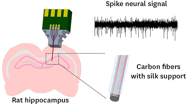
Accordingly, in the present study, we proposed a multichannel carbon fiber based electrode arrays embedded with an insertion support structure to facilitate the insertion of thin carbon fibers into deeper brain regions. In order to reinforce the stiffness of carbon fiber and to dissolve after implantation, silk fibroin was chosen for the material of a support structure. Silk fibroin is known as a biocompatible and biodegradable material derived from the domesticated Bombyx mori silkworm.2122 It is known that silk fibroin has an adjustable hydration-dependent mechanical stiffness23 and controllable degradation time. Therefore, after the silk support structure is inserted together with carbon fiber electrodes in the target brain, it can be dissolved within a specific programmed time period. In this work, we evaluated the neural signal recorded using the proposed carbon fiber based microelectrode arrays in the hippocampus region which is much deeper than the cortex. Carbon fiber based microelectrode arrays were developed with two different support materials. One is a biodegradable silk fibroin support and the other is a tungsten wire with the same dimensions as a control group. During 1-month implantation of carbon fiber based electrodes with silk fibroin and tungsten supports, the characteristics of the proposed electrode arrays have been monitored for neural spike recording. After 1 month, the reactive tissue responses were immunohistochemically analyzed.
METHODS
Carbon fiber based electrode array fabrication
Carbon fiber thread (7 µm diameter, H2550-12K; Hyosung Corporation, Seoul, Korea) is used for individual electrode shanks. Each carbon fibers were coated with a Parylene-C insulating layer (1 µm thickness) using Parylene Deposition System 2010 (SCS Inc., Indianapolis, IN, USA). In order to make electrical connections and fit into the guide structure, the insulated carbon fibers were cut into approximately 1-cm-long pieces.
An acrylic structure was designed using SolidWorks software (Dassault Systems, Wahltham, MA, USA) to guide carbon fibers and the support structure as shown in Fig. 1A and fabricated via mechanical machining (Yunwoo precision manufacture company, Hwaseong, Korea). The acrylic structure has one central groove (width, 200 µm; depth, 300 µm) to locate an insertion support and four grooves (width, 100 µm; depth, 200 µm) to guide carbon fibers. A custom-designed printed circuit board (PCB) was designed to fit with 4 carbon fibers in the grooves and to connect with a header socket for neural recording system (Fig. 1B). Four Parylene-coated carbon fibers were manually placed in each two grooves on either side of the acrylic structure and the four fibers are joined to the lower support guide under a microscope. The individual fiber was electrically connected with pads on the PCB using conductive silver epoxy (H20E; Epoxy Technology, Billerica, MA, USA) as shown in Fig. 1C.
Fig. 1
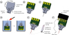
Fabrication procedure of carbon fiber based microelectrode array. (A) Acrylic structure including the guides for carbon fibers and a support. (B) PCB attached on the acrylic structure. (C) Parylene-insulated carbon fibers positioned in the acrylic structure and connected with the PCB. (D) Fire-sharpening of carbon fibers. Left: electrode array goes down into the water with the exposed fiber tips out of water. Right: a flaming torch goes by fibers on the surface and sharpened fibers are remained in water. (E) Carbon fibers with a support in acrylic structure. Left: support is positioned on acrylic structure among fibers. Right: enlarged view of the support with carbon fibers. (F) Carbon fiber microelectrode and a silver wire reference electrode are connected with a pin header socket.
PCB = printed circuit board.
The entire electrode assembly was placed on a hotplate to cure the conductive silver epoxy at 160ºC for 30 minutes. Afterwards, an insulating epoxy (AR-5; Huntsman, The Woodlands, TX, USA) was applied to protect the contact part and was cured at 120ºC for 30 minutes.
In order to sharpen the carbon fiber electrodes and lower the electrochemical impedance, fire-sharpening process was employed as previously reported.18 Briefly, the whole electrode including acrylic structure and the PCB was immersed in the water except a specific length of carbon fibers as shown in Fig. 1D. Then torch fire was applied briefly to ablate the exposed carbon fibers. After fire-sharpening, the morphology of the carbon fiber tip was obtained using scanning electron microscopy (SEM).
Following the fire-sharpening process, an insertion support was positioned in the central groove of the acrylic structure. For the insertion support, two different materials of tungsten and biodegradable silk were used to compare the characteristics after chronic implantation (Fig. 1E). Both tungsten and silk supports have the diameter of 100 µm. The silk support is prepared to be dissolved approximately for 2 days after implantation as described in the following section. Finally, the pin header socket was soldered to the PCB and one extra pin of the socket was soldered with a silver wire (AG-401265; Nilaco corporation, Tokyo, Japan) for connection with a reference electrode (Fig. 1F).
Biodegradable silk support fabrication
To make a biodegradable silk fibroin support, a polydimethylsiloxane (PDMS) mold was prepared to have a trench structure shaped in a semicircle (200 µm diameter). Silk solution (50 mg/mL; Advanced Biomatrix, San Diego, CA, USA) was applied to the trench of the mold using a syringe and cured on the hotplate at 90ºC for 20 minutes. The layer-by-layer processes of silk coating and drying were repeated until the thickness of silk support reaches about 200 µm. We repeated 7 times of the application and drying process. Then, the silk support had enough stiffness to penetrate into 0.6% (wt/vol) agarose gel mimicking brain tissues. To induce crystallization of silk material for delayed biodegradation, the silk fibroin support was treated with 70% ethanol for 5 seconds. After drying and ethanol treatment, the support shrank into a cylindrical shape with a diameter of 100 µm. This treatment condition resulted in the silk fibroin support which dissolves approximately for 2 days in the 0.5 mg/mL Protease solution (Protease from Streptomyces griseus; Sigma Aldrich, St. Louis, MO, USA). After ethanol treatment, the biodegradable silk fibroin support was located in the acrylic structure and attached with carbon fibers with slight application of additional silk fibroin solution (Fig. 1E). The silk fibroin coating for attachment was expected to dissolve in the brain shortly after electrode implantation.
Electrochemical impedance measurement
The electrochemical impedances of carbon fiber electrodes before and after fire-sharpening process was measured at 1 kHz in phosphate-buffered saline (PBS) solution using a 3-electrode based potentiostat system (ZIVE SP2; ZIVE lab., Seoul, Korea) with Ag/AgCl electrode (MF-2052; Bioanalytical Systems, Inc., West Lafayette, IN, USA) as a reference electrode and Pt electrode (CHI115; CH Instruments, Inc., Austin, TX, USA) as a counter electrode. After electrode implantation into the rat brain, the impedances of the carbon fiber electrode embedded with silk and tungsten supports were measured every two days for 1 month. Since there was no counter electrode, the impedance was measured using 2-electrode configuration with the implanted silver wire as a reference electrode and the carbon fiber as a working electrode using RHD2000 interface software (Intan technologies, Los Angeles, CA, USA). The impedance magnitudes measured at 1 kHz were compared between tungsten- and silk-support electrode arrays.
Electrode implantation
The carbon fiber based microelectrode arrays with silk fibroin or tungsten supports were implanted in hippocampal regions of 10 male Sprague-Dawley rats, weighing 250–300 g (6 rats for silk fibroin support electrodes, 6 rats for tungsten support electrodes). Rats were anesthetized with a mixture of ketamine (75 mg/kg) and xylazine (4 mg/kg). After the incision area was shaved, the rats were placed on the stereotaxic frame and the shaved region was cleaned with 70% ethanol. The eyes were covered with ointment to prevent drying eyes during surgery. After mid-line incision, the skull surface was cleaned and 4 holes were drilled on the skull for four fixation screws. A hole for the microelectrode array was drilled at 2.8 mm posterior and 1.4 mm lateral from bregma. The dura was removed using syringe needle and the carbon fiber based microelectrode array was inserted in the hippocampus region (DV, −3.5 mm). The reference wire from the electrode array was connected to the fixation screws. After implantation, the microelectrode array was fixated on the skull using dental cement (Jet denture repair; Lang dental, Wheeling, IL, USA).
Electrophysiological recording and signal processing
Using the implanted carbon fiber based microelectrode array, electrophysiological recording was performed every two days when the rat was freely behaving in the cage. The neural recording was performed to record spontaneous activity without stimulation.
The electrode was connected with a neural signal acquisition system (RHD2132 amplifier board and an RHD2000 evaluation system, Intan technologies). Acquired signal was sampled at 25 kHz sampling rate and bandpass-filtered from 0.3 to 20 kHz for neural spike recording. Recorded neural signal was analyzed using MATLAB (Mathworks, Natick, MA, USA) program. Each channel was thresholded and waveforms sorted using a spike sorting algorithm “Wave-Clus” (http://www.le.ac.uk/neuroengineering). The spikes were detected using an amplitude threshold (threshold = 5 × median  , x = band-pass filtered signal). And then with a sampling frequency of 25 kHz, this plots 64 datapoints. Spike waveforms were overlapped and the mean values at each time point are extracted as sorted signal.
, x = band-pass filtered signal). And then with a sampling frequency of 25 kHz, this plots 64 datapoints. Spike waveforms were overlapped and the mean values at each time point are extracted as sorted signal.The peak-to-peak amplitudes of the sorted waveforms were averaged for both groups of electrode arrays with silk- and tungsten-support. The percentage of electrode channels where the sorted spikes were recorded was also calculated for both groups of electrode arrays.
To determine the noise floor of each channel, 1 second of recording data was chosen where no sorted spike and no motion artifact existed. SNR was calculated as a peak-to-peak signal amplitude of the sorted waveforms divided by the six times of root mean square (RMS) value of the noise floor because the peak-to-peak amplitude of the noise floor is calculated as six times the RMS value of the noise floor.24

Immunohistochemistry
At 1 week and 4 weeks after implantation, animals were transcardially perfused with normal saline and then with 4% paraformaldehyde. After perfusion, the microelectrodes were explanted and brains were carefully extracted and postfixed in 4% paraformaldehyde for 1 hour. Then, the brains were transferred to 30% (wt/vol) sucrose solution in PBS, and stored 3 days. For immunohistochemical staining of cells around electrode tracks, the brains were horizontally sectioned with the thickness of 20 µm using cryostat-microtome (CM1850; Leica, Wetzlar, Germany). Prior to staining, the brain slices were rinsed in PBS for 10 minutes 3 times and blocked with blocking solution (4% bovine serum albumin [BSA] and 0.2% Triton X-100 in PBS) for 30 minutes. Slices were gently agitated for 2 days in a solution of 0.2% BSA and 0.2% Triton X-100 in PBS with anti-glial fibrillary acidic protein (GFAP) primary antibody (rabbit polyclonal, 1:400; Abcam, Cambridge, UK) for visualization of astrocytes and anti-CD68 primary antibody (mouse monoclonal, 1:200; Abcam) for activated microglia and macrophages. Slices were rinsed 3 times in PBS and incubated in PBS solution containing secondary antibodies (Alexa 488 goat anti rabbit, 1:500; Texas red goat anti mouse, 1:250; ThermoFisher; Waltham, MA, USA) mixed with 0.2% BSA and 0.2% Triton X100 for 4 hours. Finally, the slices were rinsed with PBS for 10 minutes 3 times and mounted on slide glasses and allowed to dry overnight at room temperature. After one drop of mounting solution (Vectashield; Vector laboratories, Inc., Burlingame, CA, USA), a coverglass was affixed on the brain slices for imaging. The fluorescence images were collected under an inverted microscope (IX71; Olympus, Tokyo, Japan) using a CMOS camera (Zyla 5.5 sCMOS; ANDOR, Belfast, UK). The fluorescence images were analyzed in terms of the radial profile of fluorescence intensity around the location of implanted electrodes using a ‘Radial Profile Angle Ext’ macro plug-in for ImageJ (National Institute of Health, https://imagej.nih.gov/ij/). After the averaged intensity profiles were normalized with background fluorescence intensity, the fluorescence profiles for GFAP and CD68 were plotted using GraphPad Prism (GraphPad Software Inc., La Jolla, CA, USA).
RESULTS
Electrode characterization
To verify the ability of the carbon fiber for neural recording, SEM images of carbon fiber tips and the electrochemical impedance were obtained. Before fire sharpening process, the carbon fiber had a blunt tip with Parylene C insulation as shown in Fig. 2. The impedances of a carbon fiber electrode were 15.76 ± 3.19 MΩ and 0.74 ± 0.15 MΩ (n = 48) in PBS at 1 kHz before and after fire sharpening, respectively (Fig. 3). This is because it increases the surface area of the exposed carbon fibers as a result of the fire sharpening process. In addition, it might be also possible that the fire sharpening induced the carbon surface modification to facilitate ionic exchange at the interface between the carbon surface and the aqueous solution.25 However, further electrochemical investigations were not performed because the impedance after fire sharpening was low enough to detect neural spikes.
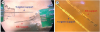
Fig. 2
Scanning electron microscopy images of carbon fibers. (A) Parylene-coated carbon fiber. (B) Carbon fiber tip after fire-sharpening.
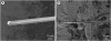
Fig. 3
Electrochemical impedance measurement of carbon fiber electrodes. (A) Impedance magnitude plot before and after fire sharpening. (B) Impedance phase plot before and after fire sharpening. (C) Bar graph of impedance magnitude before and after fire sharpening at 1 kHz in phosphate-buffered saline (mean ± standard error).
Four-channel, carbon fiber based, depth-type microelectrode arrays embedded with insertion supports were fabricated as depicted in Fig. 4. The electrodes were prepared with two different support materials of a biodegradable silk-fibroin and a non-degradable tungsten. The impedances of the electrodes with silk support and tungsten support were monitored and compared for 1 month after implantation into the hippocampal regions of rat brain (Fig. 5). The first measurement at day 3 did not show statistically different impedances between both groups of electrodes for each group (4.48 ± 0.74 MΩ from silk support electrodes and 3.24 ± 0.69 MΩ from tungsten support electrodes, 24 carbon electrodes [6 implanted arrays]). However, the impedance of the electrodes with silk support gradually increased up to 10.48 ± 0.31 MΩ until day 17 while that of the electrodes with tungsten support decreased to 1.44 ± 1.07 MΩ during the same time period. Afterwards, however, the impedance of the electrodes with silk supports decreased down to 5.01 ± 1.67 MΩ at day 31. The impedance of the electrodes with tungsten supports was 1.43 ± 0.91 MΩ on the day 29.
Neural signal analysis
In order to access the chronic recording capability of the fabricated microelectrode arrays with silk- and tungsten-supports, the neural activity was recorded and compared for 1 month. Spike sorting was performed to analyze the recorded multi-unit spiking signals. The representative sorted waveforms at different time points were presented in Fig. 6A. First, among 24 carbon fiber electrodes (6 electrode arrays) with each support, the percentage of active electrodes was calculated over time and plotted in Fig. 6B. The active electrode is defined as the electrode channel from which the spike signals were detected during recording session. On day 3 after electrode implantation, the percentages of channels with recorded units were 68.2% and 77.5% with silk and tungsten supports, respectively. Until day 15, the percentages of the channels with units were similar between two groups. However, the electrodes with silk supports showed a fluctuation of the percentage of active channels between 0% to 87.5% while the percentage gradually increased up to 100% from the electrodes with tungsten support (Fig. 6B). After day 27, the percentage of silk support electrodes was maintained above 70%, which is still higher than that of conventional microelectrode arrays made of micro-wires or microfabricated silicon as reported in previous literatures.15172026
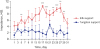
Fig. 6
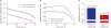
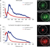
Recording capability analyses of carbon fiber based electrode array. (A) Representative waveforms after unit sorting at different time points. (B) Percentages of active channels detecting spike signals over time. (C) Mean amplitudes of sorted spike signals at each time point (mean ± SE). (D) Baseline activity of electrode with silk support and tungsten support (mean ± SE). (E) Signal to noise ratio for all units detected from the microelectrode for 1 month (mean ± SE). No data of silk support electrode for (C), (D), and (E) on day 25 because no spike signal was detected on the day.
SE = standard error.
**P < 0.01.
The amplitude of sorted spike signals was also monitored over time and compared between two groups of electrode arrays with different supports (Fig. 6C). At day 3, the mean signal amplitudes recorded from the electrode with silk support and tungsten support was 76.0 ± 7.8 µV and 76.6 ± 9.2 µV, respectively. Until day 15, the amplitude from tungsten support group decreased to 48.4 ± 2.1 µV while that of silk support was maintained at the similar level 84.5 ± 5.1 µV. After then, even though a sudden amplitude increase was observed from electrodes with tungsten supports at day 17, in general, the mean signal amplitudes from both groups were remained as similar as the initial values. At day 29, the mean signal amplitudes recorded from the electrodes with silk and tungsten supports were 81.3 ± 13.5 µV and 89.4 ± 11.0 µV, respectively.
Signal to SNR analysis
The amplitude of baseline activity were monitored for noise analysis and SNRs were obtained in order to more precisely evaluate the recording capability of the proposed carbon fiber based electrode arrays. The mean baseline activity was measured in both silk support electrode and tungsten support electrode. The average baseline activity calculated from RMS noise was 9.4 ± 0.7 µV of electrode with silk support and 9.4 ± 1.1 µV of electrode with tungsten support on day 3 (Fig. 6D). It rose at day 5 in silk support (12.3 ± 1.3 µV) and tungsten support (11.86 ± 1.7 µV) then the level of noise floor decreased until about day 15. The RMS value of noise level of electrode with silk support was 9.2 ± 1.2 µV and the noise amplitude of electrode with tungsten support was 8.5 ± 1.3 µV on the last day.
The SNR of the silk support electrodes was 1.3 ± 0.1 and that of tungsten support electrodes was 1.3 ± 0.1 on day 3 (Fig. 6E). The electrode with silk support had a peak SNR level on day 21 (1.9 ± 0.4, n = 5) and the electrode with tungsten support got a peak SNR value on day 17 (2.1 ± 0.7). After 1-month implantation, the SNR levels of both electrode types (silk support, 1.4 ± 0.1; tungsten support, 1.9 ± 0.3) slightly increased compared with the initial SNR levels, which indicated that the quality of the recorded signal was not significantly decreased for 1 month.
Immunohistochemical analysis of reactive tissue responses
To investigate the chronic reactive tissue responses of the implanted microelectrode arrays with two different types of supports, after 1-month implantation, the immunohistological fluorescence images were obtained with GFAP staining to define activated astrocytes and CD68 staining to define activated microglia and macrophages. Overall, the images showed the chronic foreign body reaction characterized by increased reactive astrocyte sheath and activated microglia around the implanted support as reported by previous literatures.92728 Compared between two different materials of support, the images from tungsten support clearly showed the larger void region with the same diameters of the support (Fig. 7). However, the smaller void area was observed in the fluorescence images from silk support electrodes, indicating that the silk support was dissolved before the imaging. The GFAP response from astrocytes in tungsten support electrode showed a higher fluorescence intensity and a wider region around the electrode compared with silk support electrode (Fig. 7A and D). The activated microglia and macrophages were also observed with high intensity around the both probe (Fig. 7B and E). The CD68 staining from tungsten supports showed a diffuse fluorescence intensity around the support which is similar to that of GFAP. However, interestingly, it appears that the CD68 staining from silk supports was observed exclusively inside of GFAP sheath. Accordingly, it can indicate that the activated microglia and macrophages migrated and filled in the spaces where the silk support existed before completely dissolved. It is also important to note that the GFAP showed that the astrocytic sheath formation occurred before the biodegradation of silk support.
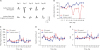
Fig. 7
Immunohistochemical staining images. (A, B) GFAP (astrocytes) staining around silk- and tungsten-supports. (C, D) CD68 (activated microglia and macrophages) staining around silk- and tungsten-supports. (E, F) merged images of GFAP and CD68 staining for each support. The each white circle indicate the footprint of the supports.
GFAP = glial fibrillary acidic protein.
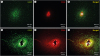
The normalized fluorescence profiles in Fig. 8 shows that peak GFAP fluorescence intensity of the tungsten support is approximately 50% higher than that of the silk support (Fig. 8A). Even though the peak CD68 fluorescence intensity was not different between different supports, the intensity profile from the tungsten support was much higher along the distance than that from the silk support (Fig. 8B). In addition, the intensity profile from the tungsten support electrode showed a clear void from 0 to 50 µm due to the radius of the support in both GFAP and CD68 staining.
DISCUSSION
There have been a few studies that employed the carbon fibers for individual channels of microelectrode arrays for in vivo neural recording. The previous studies successfully showed the advantageous properties of thin carbon fiber electrodes such as low reactive glial responses and the higher recording capability over time compared with conventional micro-wire electrodes or silicon-based microelectrode arrays. However, there was no attempt to implant the carbon fiber based electrodes into the brain regions deeper than brain cortex because the carbon fiber with a diameter less than 10 µm does not provide enough stiffness. In this study, we proposed a new carbon fiber based electrode arrays embedded with a support structure to facilitate the deeper insertion into brain tissues. In addition, in order to minimize the reactive glial encapsulation due to the large volume of support structures, we proposed a biodegradable silk support that dissolves after implantation. The fabricated electrode arrays were successfully implanted into the target region of rat hippocampus (depth, 3.5 mm).
After implantation, the electrochemical impedance of carbon fiber based electrodes with the silk support increased more than 2 times gradually until day 17 and returned approximately to the initial value after 1 month, while the electrodes with the tungsten-support electrodes showed a relatively stable impedance magnitude over the same period. The impedance increase after electrode implantation into brain tissue is typical phenomenon for chronic experiment.171926 In general, it is well known that the reactive glial encapsulation occurs around the implanted electrodes, resulting in impedance increase and deterioration of communication between electrodes and the target neurons.293031 However, in this study, the impedance increase occurred only with the electrode with silk supports, not with the tungsten support electrodes. More interestingly, the impedance of silk-support electrodes decreased back after 1-month implantation. Although further investigation is required to verify, we hypothesize that it is because the dissolving silk fibroin temporarily lowered the conductive ionic concentrations around carbon fiber electrodes, resulting in the impedance increase.32 After the silk support was completely biodegraded by endogenous enzymes or by other mechanisms, the resultant peptides or amino acids must have diffused away during the circulation of extracellular fluid over time, resulting in the slow recovery of impedances. In addition, these impedance changes might affect the percentage of active electrodes because the increase and decrease of impedance with silk-support electrodes occurred at the similar time points with the decrease and recovery of the percentage of active electrodes (Figs. 5 and 6B).
Even though there was the impedance increase and the fluctuation of the number of active electrodes, the recording capability of silk-support electrodes was eventually recovered after 1-month implantation. In addition, no significant difference was observed between silk- and tungsten-support electrodes in terms of the amplitude of spike signals, baseline activity, and SNRs. More importantly, after 1 month, both groups of carbon fiber based electrode arrays showed superior characteristics to conventional microelectrode arrays enabling a stable chronic neural recording.1626
Although no significant difference in recording capabilities was found in use of biodegradable silk supports instead of non-degradable tungsten supports, the immunohistochemical analysis showed clear different reactive tissue responses between silk- and tungsten-supports as shown in Fig. 7.
After fluorescence normalization for quantitative analysis, the silk-support electrode showed the lower peak intensity of GFAP staining and the narrower fluorescence profiles of GFAP and CD68 stainings defining activated astrocytes, microglia, and macrophages. The activation and proliferation of glial cells around the implanted electrode arrays could cause neuronal cell bodies to migrate away from electrodes due to scar tissue forming resulting in decreased signal amplitudes and SNRs.33 However, in our study, even though there were slight decreases of signal amplitude and baseline activity for 2 weeks, the carbon fiber based microelectrode with tungsten-supports did not show any significant decrease of spike signal amplitude or SNRs despite the higher fluorescence profile of reactive glial tissue responses. Over time, as the silk coating for fixing the fiber to the support dissolved, the carbon fibers would be released and located at a specific distance away from the support. Thus, although the tungsten support induced more severe reactive glial responses, the thin carbon fiber electrodes may not have been directly affected by the glial scar formation.
Our assumption was that the biodegradable silk support would exhibit a better electrode performance due to its fast dissolution, minimizing glial tissue responses, compared with the non-biodegradable supports. However, in this study, the silk-support electrode array did not clearly elicit superior properties for neural recording to the tungsten-support electrodes. The recording capabilities of both electrodes became very similar after 1-month implantation. Based on the immunohistochemical study, the tungsten supports caused more damage than the biodegradable silk supports as expected. Since the formation of encapsulating glial tissue can continue to grow for more than several months, the reactive glial responses could be more severe if the implantation period is prolonged to more than 1 month. Besides, if the number of supports increases in an array to cover larger brain area with higher spatial precision, then the degree of tissue damage will be more significant with non-degradable supports.
Silk is a biocompatible and biodegradable material, which is currently used in various applications for clinical and research purposes.343536 It has been also used as an implantable material for chronic in vivo studies.3738 In this study, silk is employed to give mechanical stiffness for microelectrode insertion into brain tissues. Even though the fabricated silk support provided enough stiffness to insert the carbon fibers into the deep brain region, it is still necessary to optimize the dissolution time of silk for stable chronic neural spike recording. The silk support was prepared to be dissolved approximately within two days based on in vitro tests using a protease solution. However, after implantation in the rat hippocampus, the results from impedance measurement and neural recording indicates that the complete biodegradation and disappearance of silk supports took approximately 4 weeks. It might be because the conditions of in vitro tests using protease solution is not properly mimicking in vivo environments in the brain. Recently, it was also reported that the role of the enzyme is not significant in the process of in vivo degradation of silk.39 Rather, they reported that the in vivo silk degradation was related to cell mobilization and phagocytotic activity. Therefore, if the in vivo degradation time of silk is optimized to be dissolved within a shorter time after implantation, it is expected that the carbon fiber based microelectrode array with a silk support can be used for chronic neural spike recording with minimized reactive glial responses.
 XML Download