

 PDF
PDF ePub
ePub Citation
 Print
Print


Introduction
Panoramic radiography is a type of tomography that shows the structure of the oral and maxillofacial region on a single 2-dimensional image.1 Only structures located in the image layer (or focal trough) of the 3-dimensional curved surface can be clearly obtained and interpreted, with diagnostic value.23 The curved image layer is influenced by several factors, including the angle of the X-ray source of panoramic radiography, the distance between the center of rotation and the film, and the width of the X-ray source.4
Therefore, it is essential to understand the exact shape of the image layer. In several previous studies, the image layers of panoramic radiography were evaluated, but the evaluation methods and criteria varied. In the studies by Brown et al.5 and Lund et al.,6 images were acquired after a pin was inserted into the arch-shaped support, and the boundary of the pin in the obtained images was subjectively read by the reader, followed by scoring the sharpness to determine the boundary of the image layer.
A method of evaluating the image layer of panoramic radiography using a lead wire pair was first presented by Hassen et al.1 The position of the lead wire was changed at intervals of 1.5 mm between the lingual and buccal sides of 8 specific areas in the arch-shaped support. The image layer boundary was determined based on the readability of 1.7 line pairs per millimeter. In 1985, a study was conducted in which a metal ball was moved in 10° increments and 1-mm increments on the arch-shaped support to determine the image layer of panoramic radiography by identifying the area with the minimum amount of distortion of the ball images.2
As the need to evaluate the image layer of panoramic radiology has emerged, a phantom is currently available for evaluating the image layer of panoramic radiography equipment (TO PAN®, Leeds Test Objects, North Yorkshire, United Kingdom). However, using this phantom, the image layer of panoramic radiography can only be evaluated at 5-mm intervals, only for a region of approximately 25 mm, and only at the anterior, premolar, molar, and temporomandibular joint (TMJ) sites. In addition, since interpretation by the experimenters is a necessary part of determining the ball boundary and measuring the axis of the ball in the obtained images, there is a limitation in that an error may occur in the evaluation process.
This study presented a new ball-type phantom that can be used to evaluate the shape and size of the image layer of panoramic radiography.
Materials and Methods
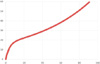
In order to obtain the arch shape of the phantom, it was necessary to determine which center line of the phantom would reproduce the average mandibular dental arch shape of Korean adult males. In order to determine the average mandibular dental arch shape of Korean adult males, 2 studies were reviewed to identify the position of 7 reference parameters of the dental arch.78 Two additional studies were reviewed to determine the position of the TMJ in Korean adult males.910 The magnification rate of cephalometric radiography was determined to be 10%,11 and corrected values were used when the parameters were measured using the acquired images. The final parameters that were used as the reference tooth positions are listed in Table 1. After determining the 8 reference points, the following formula fitting those 8 points was derived using Microsoft Excel® (Microsoft Corp., Redmond, WA, USA).
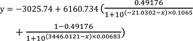
The continuous line obtained from the graph of this formula was defined as the center phantom (Fig. 1). Using the definition of the center line, the exact positions of the metal each reference point were determined. Along the center line, metal balls with a diameter of placed with a distance of 2 mm between the edge of the balls. To minimize the effects of images, the metal balls were placed only in the right arch, and the anterior region extended arch up to the left mandibular canine position.
Additional metal balls were placed along the 22 arch-shaped lines that ran parallel to the center line, of which 11 lines were placed on the buccal side and 11 lines were placed on the lingual side, with 2-mm buccolingual intervals.
When placing the metal balls along these 22 lines, the height of each ball in the horizontal plane was spaced by 2.5 mm, and consequently the balls appeared oblique when viewed from the side. The resulting platform was named the Panorama phantom.
When the balls were positioned in this way, a single panoramic radiograph could be obtained without the balls overlapping.
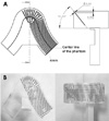
In the process of placing the balls, the gaps between the balls were not constant because of the shape of the dental arch. The balls were placed in a converging shape on the lingual side, and in a diverging shape on the buccal side. To deal with the problem that the spacing between some balls was too wide or too narrow, an additional ball was placed in the center between 2 balls when the center-to-center spacing between adjacent balls was 8 mm or more. When center-to-center spacing between adjacent balls was less than 3 mm, the distal ball was omitted. The final design of the panoramic radiography phantom is shown in Figure 2A. The actual model of the Panorama phantom is shown in Figure 2B.
To evaluate the effectiveness of the phantom, panoramic radiographs of the Panorama phantom were obtained using an OP-100® (Instrumentarium Dental, Tuusula, Finland) apparatus at Seoul National University Dental Hospital. The images were obtained with the optimal parameters according to the user's manual for imaging adult males, which were regularly used in the department (73 kVp, 10 mA, 17.6 s). The midpoint of the incisor point along the center line was matched to the center of the incisive notch on panoramic radiography. A tripod water level was used to accurately position the phantom. Additional bone and soft tissue attenuation was not reproduced to compensate for the X-ray attenuation caused by the acrylic resin placed on the ball. The exposure was repeated 3 times to minimize errors.
To analyze the obtained panoramic phantom images, MATLAB®(Mathworks Inc., Natick, MA, USA) was used. In order to clearly emphasize the boundaries of the obtained images of the balls, a noise reduction filter was applied, and then ellipse detection was applied with a universal threshold to detect the boundaries of the balls obtained in circular or elliptical shapes in the image. Using these boundaries, the lengths of the long and short axes of the balls were measured, and the difference ratio of the 2 lengths was used as an index representing the degree of ball deformation (ball distortion rate).

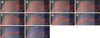
Several image layer boundaries were obtained by applying various distortion rate thresholds, ranging from 5% to 50% with 5% increments. The balls satisfying each distortion rate threshold were marked with red elliptical lines, and the balls that did not satisfy the corresponding distortion rate threshold were marked with blue lines. In order to determine the image layer boundaries, the outermost sides of the red balls inside 2 or more consecutive blue balls were connected, considering errors in the manufacturing and image acquisition process.
Results
In Figure 3, the balls satisfying each distortion rate threshold are shown in red, and the balls that did not satisfy that threshold are shown in blue.
With a 50% distortion rate threshold, most areas including metal balls (91.5%) were defined as the image layer. As the distortion rate threshold decreased, the number of balls satisfying the threshold decreased, and the image layer became narrower. In particular, as the distortion rate threshold approached 5%, the balls satisfying the condition were observed to show a nearly linear form. With a 5% distortion rate threshold, the number of the balls inside the focal layer was 51, corresponding to 7.2% of the total of 704 balls. The border of the image layer of the TMJ region in the image shifted downward. This indicated that the image layer of the TMJ region was medially located.
Discussion
In the Panoramic phantom developed in this study, data were used from the mandibular dental arches and condyles of Korean adult males as references for positioning the metal balls. These references could be varied considering the characteristics of each country or race. Since the Panorama phantom was designed to have the metal balls positioned in a continuous manner with a large buccolingual width, it could be possible to project various reference data for different racial groups onto the Panorama phantom. The metal balls could be localized with high agreement to establish the reference center line for evaluating the relationship between the specific shape of the jaw and the actual image layer of the panoramic radiography being used. Therefore, this technique could be applied to various arches by altering the position of the metal balls used as the center line, even with a single Panorama phantom.
As the distortion rate threshold decreased, the number of balls satisfying the threshold decreased and the image layer became narrower. In particular, as the distortion rate threshold approached 5%, the balls satisfying the condition were observed to have a nearly linear form. This showed that the Panorama phantom accurately reflected the characteristics of panoramic radiology and enabled accurate up-level evaluations.
The minimum distortion rate threshold that yielded a width of at least 10 mm, corresponding to the average thickness of the jawbone, was 15% in all regions.
Using the newly developed Panorama phantom, it is possible to precisely evaluate the image layer of panoramic radiography. This phantom can be used evaluate all mesiodistal areas with large buccolingual width (46 mm).
Future studies are currently planned in which this phantom will be used to visualize the image layer, the direction of the central ray, and rotational centers of panoramic radiography.

 XML Download