

 PDF
PDF ePub
ePub Citation
 Print
Print


INTRODUCTION
Cephalometric radiography can be used for a wide variety of orthodontic applications, such as understanding craniofacial growth and development, analyzing the association between craniofacial anatomy and the dental arch, establishing a treatment plan, and evaluating therapeutic efficacy.1 In particular, frontal cephalograms provide useful data for analysis of dentoskeletal asymmetries, including horizontal maxillomandibular discrepancies and maxillary bone inclination.234
Frontal cephalograms can be obtained in the anteroposterior (AP) or posteroanterior (PA) projections according to the direction of incident radiation, and PA cephalograms are commonly used for landmark identification. PA cephalograms offer advantages over AP cephalograms for landmark identification because the anterior facial structures, which are regions of interest (ROI), are closer to the film and hence require less magnification than the structures farther from the film, thus mitigating the penumbra phenomenon5 and yielding clearer images.
For this reason, frontal cephalograms are obtained in the PA projection in clinical settings. For orthognathic surgical simulation, however, AP cephalograms are required for image synthesis using frontal cephalograms and corresponding facial images, which are used to generate computer simulations of the patient's frontal facial photographs; these simulations are used to predict facial soft tissue changes, because AP cephalography has the same projection mode as facial photography. Despite this necessity, there is still a remarkable lack of relevant research and treatment in this field, because obtaining an additional frontal cephalogram in the AP projection only for the purpose of image synthesis is not easy in clinical practice.
The recently developed cone-beam computed tomography (CBCT) technique6 is widely used in dentistry. For example, CBCT images reconstructed in three dimensions are examined from all directions for diagnostic analysis of impacted teeth or maxillofacial morphology. Moreover, algorithms have been developed to easily generate various types of two-dimensional (2D) images, including cephalograms, from CBCT scan data. Studies have reported the use of CBCT-generated lateral cephalometric radiographs78910 or frontal cephalometric radiographs,71112 as well as the results of reliability testing for these images.
In addition to lateral cephalograms or frontal PA cephalograms, the methods proposed in these studies can also be used to easily generate frontal AP cephalograms from CBCT scan data without additional exposure to radiation. As the first of its kind, this study examines the feasibility of using AP cephalograms for anatomical landmark identification by assessing its reproducibility. To this end, landmark identification errors were compared between PA and AP cephalograms generated from CBCT scan data in clinical settings.
MATERIALS AND METHODS
The present study was approved by Institutional Review Board of Chonnam National University Dental Hospital, Gwangju, Korea (CNUDH-2015-005). Orthodontic patients with both PA cephalograms and CBCT scans from their initial visit were enrolled. Participants with missing teeth and restorations with crowns or bridges were excluded. Twenty-five orthodontic patients with both PA cephalograms and CBCT scans from their initial visit were selected by assessing the data collected by the orthodontic department. CBCT scan data were obtained using a CBCT scanner (Alphard Vega; Asahi Roentgen Ind. Corp., Kyoto, Japan) under the following conditions: 80 kV, 5 mA, 0.39 × 0.39 × 0.39 mm voxel size, and a 200 × 179 mm field of view. CBCT scanning was performed using the embedded reference ear plug (REP)13 and head posture aligner (HPA)14 to ensure standardized volume orientation by constructing a reference axis for postural adjustment in subsequent CBCT volume images.
AP and PA cephalogram generation
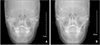
Digital Imaging and Communications in Medicine (DICOM) files obtained with CBCT scanning were loaded on the three-dimensional imaging computer program OnDemand3D™ (Cybermed Inc., Seoul, Korea) and reconstructed as volume images. The cephalogram was aligned to the reference position using the right and left ball markers in the REP and the wire indicator in the HPA. More specifically, the indicators of the right and left ear rod centers were positioned on their respective ball markers on the screen of the “X-ray generator” menu such that the virtual central ray passed through both ball markers, and the posture in the cephalogram was adjusted by vertically rotating it around the two markers such that the HPA wire indicator was horizontally aligned in the AP projection. When the posture was aligned to the reference position, frontal cephalograms were generated in both AP and PA projections, with the subject facing forward and backwards with reference to the virtual central ray, respectively. The same perspective view as in actual frontal cephalometric radiographs was implemented by entering 150 cm and 15 cm as the camera-to-film and ear rod-to-film distances, respectively, when configuring the X-ray generator environment (Figure 1).
Landmark identification
In this study, which was conducted to compare the reproducibility of landmark identification between AP and PA cephalograms, the crista galli (Cg), anterior nasal spine (ANS), and menton (Me) were used as midline landmarks, and the latero-orbitale (Lo), jugal process (J), and antegonion (Ag) were used as bilateral landmarks. Four orthodontists experienced in landmark identification on frontal cephalograms (≥ 100 cases) and four general dentists were assigned to the experienced and inexperienced examiner groups, respectively. The examiners were provided with the definitions of the six cephalometric landmarks, as presented in Table 1, to ensure clear understanding of each landmark position. They performed landmark identification on 50 cephalometric radiographs (25 AP and 25 PA cephalograms) loaded on the analysis program V-ceph 6.0 (Osstem, Seoul, Korea). The landmark positions estimated on each image were saved as x, y coordinates (Table 1).
Comparison of landmark identification errors in AP and PA cephalograms
Quantitative comparison of landmark identification errors in the AP and PA cephalograms was performed by setting the overall mean estimate of each landmark as its best estimate15 and defining the landmark identification error as the difference between the best estimate and the corresponding landmark identification performed by each examiner. The inter-examiner error was determined by setting the mean estimates of the two groups (four experienced vs. four inexperienced examiners) as their respective best estimates and calculating the distance from the best estimate to each landmark identification. In addition to calculating the straight-line distance to the best estimate as the error at each landmark, horizontal and vertical errors were also calculated by breaking down the straight-line distance into the horizontal and vertical components in order to gain a more accurate understanding of error patterns.
Statistical analysis
SPSS ver. 17.0 (SPSS Inc., Chicago, IL, USA) was used for statistical analysis. The averaged errors of the experienced and unexperienced examiner groups were defined as their respective errors, and the differences in errors between the AP and PA cephalograms at each landmark in terms of the straight-line distance and its horizontal and vertical components were obtained using the means and standard deviations calculated for 25 AP cephalograms and 25 PA cephalograms. Additionally, paired t-test was performed to assess the statistical significance of each difference thus obtained.
RESULTS
Error pattern in landmark identification on frontal cephalograms
The landmark identification errors on frontal cephalograms ranged between 0.5 and 1.2 mm depending on landmark position, irrespective of experience status (experienced vs. unexperienced examiners) and projection mode (AP vs. PA). Thus, error occurrence tended to depend on the inter-landmark differences rather than inter-examiner (experienced or unexperienced) or interprojection (AP or PA) differences, with the smallest and greatest differences incurred at the Ag and Cg, respectively (Tables 2 and 3).
The analysis of landmark identification errors in the horizontal and vertical directions showed no significant differences between the errors in the horizontal and vertical directions at the bilateral landmarks. However, the midline landmarks tended to show larger errors in the horizontal or vertical directions, with the Cg and ANS showing greater errors in the vertical direction and the Me in the horizontal direction, in comparison with the other landmarks (Tables 4 and 5).
Comparison of errors between the AP and PA cephalograms
Comparison of landmark identification errors between AP and PA cephalograms revealed that larger errors tended to occur in AP cephalograms and were more markedly incurred by experienced examiners, who performed better on PA cephalograms. However, the differences did not reach statistical significance at any of the landmarks (Tables 2 and 3).
Each error was compared in terms of its horizontal and vertical components as well. As in the straight-line distance, larger landmark identification errors were made on AP cephalograms in both horizontal and vertical directions. Particularly large horizontal and vertical errors occurred at the Lo and Ag, respectively. Errors at the Ag were incurred by only unexperienced examiners, whereas both experienced and unexperienced examiners incurred larger horizontal errors at the Lo with respect to those at the other landmarks. However, none of the differences in errors between AP and PA cephalograms reached statistical significance, even including the Ag and Lo (Tables 4 and 5).
DISCUSSION
To predict the soft tissue changes induced by orthognathic surgery, it is necessary to synthesize an image from a cephalogram and a corresponding optical image of the patient's face. This can be done only if the cephalogram has the same projection mode as the optical image. Since an optical image is obtained in the perspective view of the face, a CBCT-generated frontal cephalogram should also have the perspective view. Although many computer programs have been developed to derive 2D radiographs from CBCT-generated DICOM files, most of them generate images in a parallel projection. In this study, OnDemand3D™ was used because it provides an algorithm for generating images in the perspective view as well.
For the purpose of this study, which intended to compare the reproducibility of landmark identification on CBCT-generated frontal cephalograms in the AP and PA projections, it was important to ensure the same craniofacial posture for generating the AP and PA cephalograms. Unlike a lateral cephalogram, in which the relationships between the cephalometric landmarks do not undergo any significant changes when the craniofacial image is being vertically rotated, landmarks on a frontal cephalogram are known to undergo not only changes in the vertical direction, but also in the horizontal direction, extending or contracting according to the landmark-to-film distance.1617 To ensure alignment of the volume images to the same posture for subsequent AP and PA cephalograms, REP and HPA were used for CBCT scanning in this study. When generating AP and PA cephalograms, the same posture can be ensured by establishing a reference axis with the right and left ear plug ball markers displayed on the CB volume image and horizontally controlling the HPA wire indicator.
The AP and PA cephalograms generated with the computer program were used for cephalometric landmark identification. Four inexperienced and four experienced examiners identified six landmarks (Cg, ANS, Me, Lo, J, and Ag) on these cephalograms, and the identification errors at each landmark were compared. The findings indicated that inter-landmark differences were greater than inter-projection (AP vs. PA) differences. For example, assessments of the Ag involved smaller errors, whereas larger errors occurred in identifying the Cg and ANS. For a more detailed examination of the error patterns, the horizontal and vertical components of the errors were analyzed. Errors at the Cg and ANS mainly occurred in the vertical direction, and those at the Me mainly occurred in the horizontal direction. This may be due to the fact that all participating examiners were accustomed to identifying the Cg and ANS in the horizontal direction because they are commonly used for establishing the median reference line, but were less experienced in performing careful identification of these landmarks in the vertical direction. On the other hand, the examiners committed larger errors in the horizontal direction when identifying the Me, presumably because its identification is usually performed along the contour of the mandible inferior cortical bone. El-Mangoury et al.18 investigated landmark identification errors on frontal cephalograms using human subjects and dry skulls and reported landmark-specific directionalities. Likewise, Athanasiou et al.,19 who investigated 34 types of landmark identification errors using frontal cephalograms, reported that each landmark showed a specific directionality according to its definition.
The error comparison between the CBCT-generated AP and PA cephalograms revealed slightly more errors in AP cephalograms. This is a natural result attributable to the disadvantage of AP cephalography due to the position of the ROI, i.e., the anterior facial area is farther from the film than in PA cephalography, which necessitates greater magnification of the structures and thus increases the penumbra phenomenon, inevitably resulting in diminished image clarity. For a more detailed understanding of the error patterns associated with AP cephalograms, errors were examined in the horizontal and vertical directions. As a result, the Lo and Ag were found to show greater horizontal and vertical errors, respectively, compared with other landmarks. While the vertical error at the Ag occurs due to inexperience, given that it involved only inexperienced examiners, errors at the Lo tended to be greater on AP cephalograms than on PA cephalograms in both experienced and inexperienced examiners. This may be explained by the fact that the oblique orbital line is anatomically positioned in the anterior facial area and thus appears wider in the horizontal direction in the AP projection mode than in the PA projection mode, resulting in greater horizontal errors at the Lo, the point at which the oblique orbital line meets the external orbital contour.
Despite the slightly higher error-proneness of AP cephalograms in comparison with PA cephalograms, no significant differences were found in statistical analysis at any of the landmarks. This implies that the reproducibility of landmark identification on frontal cephalograms in the AP projection is not lower than that in the PA projection. This high reproducibility of landmark identification on AP cephalograms is attributable to the progresses made in CBCT image processing technology and the development of computer algorithms.202122
The results of this study demonstrate the feasibility of using CBCT scan data for generating frontal cephalograms in the AP projection depending on clinical necessity, because the reproducibility of landmark identification on AP cephalograms is practically as high as that on PA cephalograms. Image synthesis using similarly generated AP cephalograms and corresponding optical images is expected to facilitate creation of a computer program for predicting or simulating the changes in facial morphology after orthodontic treatment or orthognathic surgery. As the pre- and post-treatment patient database grows in the future, frontal cephalogram simulation software can be developed for clinical applications, and the method presented in this study is expected to serve as the basis for building such a system.


 XML Download