

 PDF
PDF ePub
ePub Citation
 Print
Print


INTRODUCTION
Magnetic resonance imaging (MRI), computed tomography (CT), interventional angiography, general X-ray, mammography, and fluoroscopy are the best known medical science imaging procedures. Interventional angiography is a method of performing angiography that uses X-rays and contrast medium, enabling visualization of vascular and non-vascular structures (1). Many reports have been published in which percutaneous transluminal angioplasty (PTA) and endovascular stent placement were performed on patients with ischemic vascular disease (2345), embolization was performed on ruptured vasculature (678), and chemoport insertion was performed via a central catheter using interventional angiography. Based on those studies, we know that interventional angiography can be useful when treating a variety of diseases (91011). However, radiation exposure is an important factor in interventional angiography. One study, done in the early 1992, investigated fluoroscopically-induced skin injuries. The International Commission on Radiological Protection (ICRP) cautioned about the hazard of radiation exposure and announced its recommendations to prevent radiation exposure during an intervention procedure in publication 85, “Prevention of radiation hazard during an intervention procedure” (1213). Balter et al. (12) reported that the epidermis, dermis, subcutaneous tissue, subcutaneous fat, and muscle can be injured during an intervention procedure, and that the extent of injury is dependent on fluoroscopic time. Koenig et al. (14) reported 73 injuries caused by fluoroscopy and suggested that fluoroscopy should be done with the minimal possible dose. Since the dose of radiation given during an interventional angiography can directly injure human skin, an effort to minimize dose is essential. In publication 85, the ICRP recommended that radiation dose should be decreased by evaluation of the performance of the radiation equipment and the technical factors involved (13). The basic characteristics of angiography equipment are that it has the form of a C-arm and the X-ray tube is underneath the table. It is not possible to control collimation by controlling the light emanating from the tube, as is possible with general X-ray equipment, because the table is located between the tube and the detector. Therefore, focusing on the part of the patient to be irradiated entails exposing the patient to radiation. Accordingly, this study developed a reversed laser beam collimator (RLBC) for the first time, which is capable of focusing light from the detector to the tube during interventional angiography. This study will investigate whether the ability to see the X-ray field with the naked eye will decrease the equipment operation time, time needed for fluoroscopy, and dose area product (DAP).
MATERIALS AND METHODS
Manufacturing of the RLBC
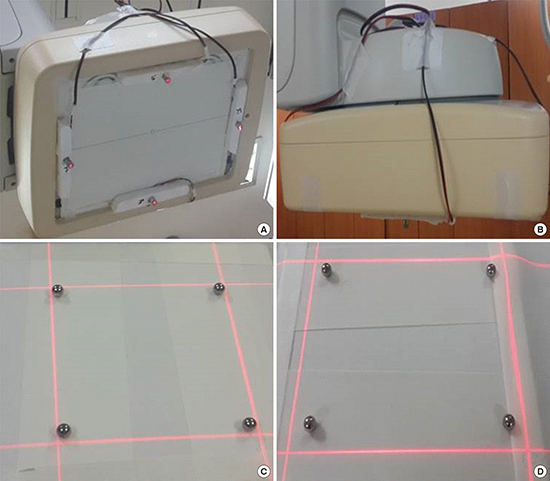
The laser used in this study is produced by a red line laser diode (Mactron, Guangdong, China). Its output power is min2.5 mW–max5.0 mW, working current is min10 mA–max25 mA, working voltage is min2.3 VDC–max8.0 VDC, wavelength is 650 nm, color is red, diameter is 12 mm, and length is 35 mm. The timer chip is an ATmega88 AVR Microcontroller (Atmel Corporation, San Jose, CA, USA), power is 1.8–5.5 V, and the infrared ray receiving device is an LTOP-ML38ATH (Lite-on, Taipei, Taiwan), which is a one-mold small-package type that uses a 5 V supply. The ATmega88 AVR Microcontroller and the infrared ray receiving device were fixed on a self-made dome-shaped plastic object with a diameter of 130 mm and a height of 50 mm. The supporting frame used to fix the laser diode module is made of polystyrene and it is 100 mm wide, 8 mm tall, and 20 mm deep. A 12 mm diameter hole was prepared in the center so that the laser diode module can be placed inside. The acryl panel is 415 × 330 mm. An area 75 mm wide and 15 mm long on both sides of the acryl panel were cut off so that the panel would not interfere with the detector-fixing device. If the acryl panel were to cover the detector, it would absorb and scatter X-rays and negatively impact image quality. The internal dimensions are 280 × 365 mm. The red line laser diode module was connected to the timer chip and it was confirmed to be operating normally. The laser diode module was inserted into the central groove of the supporting frame. The supporting frame and the acryl panel were fixed with silicon. This was done 4 times so that the laser diode module was fixed in all 4 directions of the acryl panel through the supporting frame. After the acryl panel was fixed to the detector, the lasers in the 4 planes were focused on the center of the X-ray generation equipment. The dome containing the timer chip and the infrared ray receiving device was fixed to the top of the detector (Fig. 1). The National Electrical Code (NEC) format infrared ray with 38 kHz is operated by remote control. When the infrared ray is detected by the infrared ray receiving device, the power turns on. Then, the 4 diode modules run for 10 seconds (Fig. 1).
Fig. 1
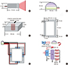
A schematic diagram of RLBC. (A) Red line laser diode module. (B) The domed plastic container housing the timer chip and infrared ray receiving device, the timer chip, and 4 laser diode modules are connected. (C) Polystyrene laser diode module fixing device. (D) The acryl panel to be combined with the detector. (E) The arrangement of the parts viewed from the bottom. (F) A mimetic diagram of RLBC operation. An NEC format infrared ray with 38 kHz is operated by a remote control. The infrared rays are received by the RIR, the infrared ray receiving device, and 5 V power source. Then, the 4 diode modules at the Tc run for 10 seconds.
RLBC = reversed laser beam collimator, NEC = National Electrical Code, RIR = received infrared ray, Tc = timer chip.
Test method
The equipment used in this study was a C-arm type Allura Xper FD 20 (Philips, Amsterdam, The Netherlands). In the first test, the iron balls were located on the table within 2 mm of the 4 edges of the image field. The table was located as far out and down as possible, and its height was fixed at 75 cm. Then, 30 radiologists were divided into 2 groups. One group worked on the test without the use of the RLBC, and the other group worked on the test after the RBLC was put into place. They performed location fixing until the iron balls entered into the image field (Fig. 2). The time from immediately before the start of table moving until the final imaging (the time for location fixing), the time needed for fluoroscopy, and the final dose (DAP) were compared between the 2 groups. In the second test, the iron balls were located within 10 mm of the 4 edges of the image field, while all other conditions were the same as in the first test (Fig. 2). Automatic exposure control (AEC) mode was selected when doing fluoroscopy. The tube voltage was 49 kV and the tube current was 3 mAs. The fluoro-prefilter was 0.40 mmCu + 1.00 mmAl. SPSS for Windows, version 17.0 (IBM, New York, NY, USA) was used for statistical analyses. Paired t-tests were used to compare the average time needed for location fixing, fluoroscopy, and DAP before and after the use of the RLBC. A P value of 0.001 or smaller was taken to indicate a statistically significant difference.
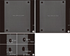
Fig. 2
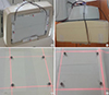
The RLBC mounted on the instrument. (A) The detector with RLBC as seen from the bottom. (B) Seen from the side. (C) The field confirmed by RLBC after locating the iron balls within 2 mm. (D) The field confirmed by RLBC after locating the iron balls within 10 mm.
RLBC = reversed laser beam collimator.
Measurement of radiation dose during fluoroscopy
Measuring the entrance surface dose (ESD) and tissue-absorbed dose with a dose-measuring device is desirable in radiation dose monitoring; however, it is almost impossible to measure those values during actual fluoroscopy. Therefore, the measurement of fluoroscopic time, air kerma at the reference point, and DAP were used to monitor radiation dose. Fluoroscopic time is significantly related to radiation exposure and it can be easily recorded without using a separate measuring device; however, the fluoroscopic time is only reference data because it does not reflect the intensity of X-ray irradiation, the performance of the equipment, or the irradiated area. The air kerma at the reference point estimates ESD by calculating or measuring the energy of air particles charged at a fixed reference point. However, the value obtained using the DAP meter, instead of direct measurement, contains error because it does not consider scattered rays. DAP is the X-ray intensity within the fluoroscopy area. The DAP meter is located at the front of the collimator of the X-ray tube. In the range limited by collimation, the DAP value is the same regardless of distance and it can be confirmed in real time. DAP is the most effective measurement method in actual clinical practice because it yields the absorbed dose and the effective dose received by a patient through a calculation. Many studies have used DAP to measure the radiation dose. Bor et al. (15) reported that there is not a large difference between the dose directly measured with a thermo-luminescent dosimeter (TLD) and the value obtained by multiplying a conversion factor with the DAP. Therefore, this study used fluoroscopic time and DAP to compare radiation doses.
RESULTS
Existing C-arm type angiography equipment requires the location of a patient to be determined by fluoroscopy because there is no RLBC; fluoroscopic time and radiation dose are therefore greater than absolutely necessary because of the time needed for location fixing. The test with the iron balls placed within 2 mm of the edges of the image field assumed that the top, bottom, left, and right areas of the patient would be focused as much as possible, while the test with the iron balls within 10 mm of the edges of the image field allowed for some margin.
The test with the iron balls within 2 mm of the edges of the image field
In the test with the iron balls within 2 mm of the edges of the image field, the time for location fixing decreased from 23.7 ± 4.7 seconds before using the RLBC to 14.2 ± 3.6 seconds after using the RLBC, the fluoroscopic time decreased from 18.5 ± 4.2 seconds before using the RLBC to 2.4 ± 1.9 seconds after using the RLBC, and the DAP decreased from 70.4 ± 10.6 mGycm2 before using the RLBC to 5.5 ± 4.7 mGycm2 after using the RLBC (P < 0.001) (Table 1) (Fig. 3). The average time required for location fixing decreased by 9.5 ± 1.1 seconds, which is a 40.2% decrease. The fluoroscopic time was reduced by 16.1 ± 2.3 seconds, an 87% decrease, and the DAP changed by 64.9 ± 5.9 seconds, a 92.1% decrease.
Table 1
The test with the iron balls within 2 mm of the edges of the image field

Fig. 3
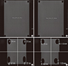
RLBC in the test with the iron balls within 2 mm from the edges of image field. (A) The image of the fixed location without using the RLBC in the test with the iron balls within 2 mm from the edges of image field. (B) The image of the fixed location when using the RLBC. (C) and (D) Confirmation that the iron balls are within 2 mm from the edges of the image field.
RLBC = reversed laser beam collimator.
The test with the iron balls within 10 mm of the edges of the image field
In the test with the iron balls within 10 mm of the edges of the image field, the time needed for location fixing decreased from 19.0 ± 3.9 seconds before using the RLBC to 5.3 ± 0.5 seconds after using the RLBC, the fluoroscopic time decreased from 13.8 ± 3.9 seconds before using the RLBC to 0.8 ± 0.4 seconds after using the RLBC, and the DAP decreased from 58.6 ± 10.1 mGycm2 before using the RLBC to 1.4 ± 0.5 mGycm2 after using the RLBC ( P < 0.001) (Table 2) (Fig. 4). The difference in the average time needed for location fixing was 13.7 ± 3.4 seconds, which represents a decrease of approximately 71.8%. The difference in fluoroscopic time, 13.0 ± 3.5 seconds, was a 94.2% decrease, and the difference in the DAP, 57.2 ± 9.6 seconds, was a 97.6% decrease.
Table 2
The test with the iron balls within 10 mm of the edges of the image field

Fig. 4
RLBC in the test with the iron balls within 10 mm from the edges of image field. (A) The image of the fixed location without using the RLBC in the test with the iron balls within 10 mm from the edges of the image field. (B) The image of the fixed location when using the RLBC. (C) Confirmation that the iron balls are within 10 mm of the edges of the image field.
RLBC = reversed laser beam collimator.
DISCUSSION
Radiation exposure from medical procedures brings with it stochastic or deterministic risks, such as cancer, cataracts, red spots, and hair loss. Nevertheless, radiography is widely used in diagnosis and treatment because the benefits of using radiography outweigh its negatives. Interventional radiography using fluoroscopy has the merit of enabling diagnosis and treatment at the same time. It can be used to detect and treat various diseases, it is safe, and it results in better or at least the same results as surgery while being less invasive (1617). However, radiation exposure remains an important issue because certain body parts are exposed to radiation for a long period of time and many people in the radiography room, including the patient, interventionist, radiologic nurse, and radiologic technologist, are exposed to radiation. This became a concern because of many reports on skin damage and hair loss in patients treated with interventional radiography (121418). There have also been reports on the possibility of disorders developed by interventionists because of occupational exposure (192021). Roguin et al. (22) reported that malignant tumors occurred on the left side of the brains of 4 interventionists, and the tumors were related to the X-ray generation device. In September of 2000, the ICRP recommended, in ICRP publication 85, that dose-decreasing methods should be identified and enforced by evaluating the performance of radiation equipment and other technical factors. The ICRP also suggested that attention should be paid to the hands of interventionists, which are exposed to direct X-rays, scattered rays, and leaked rays (13). Common methods of decreasing radiation exposure in interventional radiography are pulsed fluoroscopy (23), radiation protectors (such as wrap-around protective aprons, protective glasses, and ceiling-type protective viewing windows), increasing the distance between the patient and the X-ray tube, decreasing the distance between the image receptor (detector) and the patient, and using high KV and low mAs (24). However, these methods are already considered during a procedure and they are reflected in the total dose. Even so, the amount of exposure during various procedures has not been resolved. Therefore, new methods of decreasing radiation exposure should be considered. Accordingly, this study, inspired by the light collimator used in general radiography, developed a novel method of reducing radiation exposure.
General fluoroscopy equipment used in interventional angiography is C-shaped; the X-ray generation device is located under a table, on which a patient lies, in order to reduce exposure of the patient/interventionist to radiation, and the imaging detector is located above the patient. Therefore, it is not possible to use a light collimator to confirm the X-ray field by locating a small electric bulb on the X-ray generation device, as is done in a general X-ray procedure. This is why location fixing by fluoroscopy is required to confirm the position of the area of the patient to be irradiated. This study developed an RLBC to eliminate unnecessary radiation exposure and performed 2 different kinds of tests. In the first case, it was necessary to fix the location accurately within 2 mm from the edge of the image field. In the second case, a wider margin, 10 mm, was permitted. The tests showed that it was possible to decrease the time needed for location fixing, fluoroscopy time, and the DAP. The time for location fixing decreased by 40.2% and 71.8%, the fluoroscopic time decreased by 87.0% and 94.2%, and the DAP decreased by 92.1% and 97.6% (2 and 10 mm margins, respectively). In other words, using an RLBC allows for much faster identification of the target region than does fluoroscopy, and we confirmed that using RLBC is an effective way to decrease radiation exposure.
Since this study required some images for tests, fluoroscopy was also used in the test with the RLBC; however, it is believed that there would be no radiation received from fluoroscopy in actual clinical location fixing. Therefore, use of an RLBC is a good way to decrease radiation exposure during interventional radiography. However, there are some issues with the RLBC at this stage. One issue is that the method may cause infection in patients if the RLBC were to become disengaged because the RLBC is not made by the manufacturer of the X-ray equipment and it is located externally to the detector. Another issue is that moving the detector can cause sensor error. These issues can be resolved easily by locating the RLBC in the detector when further developing the equipment. The other important issue is that focusing the RLBC, which is done on the basis of the focus of the X-rays, can go wrong if the detector moves up or down. Additional studies are required so that the angle against the X-ray focus can be adjusted depending on the distance between the red line laser diode module and the detector.
In conclusion, the RLBC developed in this study has been confirmed as a new method of decreasing radiation exposure in patients and interventionists during interventional radiography. However, the RLBC is still in a basic stage and it has certain limitations, which need to be addressed in additional studies. This study can be utilized for basic information in further developing the RLBC and consequently contributing to decreasing exposure to radiation.
 XML Download