

 PDF
PDF ePub
ePub Citation
 Print
Print


INTRODUCTION
Dental implants were originally proposed by Brånemark for the osseointegration of titanium materials,123 and many dental implant systems have been developed for use in clinical settings.4 Numerous studies have been conducted regarding the optimal type of implant-abutment connection for successful dental implant treatment.45
The most common type of connection for many years, implant-abutment external connection (EXT), was first introduced as the Brånemark Implant System (Nobel Biocare AB, Göteborg, Sweden).6 In addition, implant-abutment internal connection (INT) was introduced as the ITI Implant System (Institute Straumann AG, Waldenburg, Switzerland)4 and remains widely used because of several merits, including its stable self-locking interface and lack of mechanical problems (e.g., abutment screw loosening and fracture), compared with EXT.4789 Nevertheless, because INT is less able to prevent vertical motion than EXT, vertical displacement occurs during screw tightening in INT.101112
Axial displacement of dental implant prostheses is caused by any of the five factors. The first factor is axial displacement in connection with impression coping for making impressions.131415 The second factor is displacement when connecting a laboratory analog to impression coping to fabricate a working model of the implant. The third factor is displacement during the mechanical work of producing a prosthesis in a working model of an implant. The first three factors are due to hand tightening,1617 and axial displacement occurs at torques of approximately 10 N·cm or 11 – 38 N·cm.1718 The fourth factor is displacement at the manufacturers' recommended torque10 during screw tightening. The fifth factor is displacement because of repetitive load in the oral cavity.1319 Hence, axial displacement of dental implant prostheses may differ depending on tightening torque, repetitive load, and the type and material of implant-abutment connections.2021
The trial adaptation of an implant prosthesis in an abutment with axial displacement may greatly affect occlusal contact with adjacent teeth, and abutment screw loosening may occur.2223 Axial displacement with multiple causes leads to an unfit implant prosthesis and adversely affects oral function.2425 Because of this problem, direct distance is measured by using a micrometer to determine the axial displacement of an implant abutment.101319 Alternatively, displacement can be measured by using a three-dimensional (3D) digital image correlation technique.202627 Notably, a more precise and accurate measurement method is lacking. Thus, this study measured and analyzed axial displacement by using a new method.
The purpose of this study was to measure the difference in axial displacement between hand tightening (10 N·cm) and screw tightening at the recommended torque (30 N·cm), according to the type of implant-abutment connection. A contact scanner was used to analyze displacement with a 2D and 3D comparative method. The null hypothesis was as follows: no difference exists in axial displacement among the four types of abutments. In addition, to compare the overall displacement (3D) and vertical displacement (2D) of the abutment, overall and vertical displacement values were assumed not to differ among the four types of abutment.
MATERIALS AND METHODS
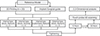
This study involved the following processes. First, working models were fabricated by using a 3D printer, then implants were placed and tightening torques were added at 10 and 30 N·cm with a contact scanner. These were scanned; then, 2D and 3D analyses were conducted (Fig. 1).
To determine appropriate sample size, a pilot experiment was conducted three times; for each abutment, a sample size of five was calculated by using power analysis software (G*Power v3.1.9.2, Heinrich-Heine-University, Düsseldorf, Germany) (actual power = 100%, power = 99%, α = .05).
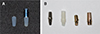
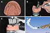
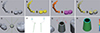
For an in vitro study, models missing mandibular left second premolars were scanned with an oral scanner (Aegis PO, Digital Dentistry Solution, Seoul, Korea) to acquire stereolithography (STL) files. Then, 20 models were produced in 16-µm layers by using a 3D printer (ZENITH, Dentis, Daegu, Korea). To prevent model abrasion by the contact scanner, resin was selected as the material for the model (ZMD-1000B, ZMD0171208B02, ZENITH). In addition, implants were placed in the same position in each model by using a surgical guide designed for placing implants in the mandibular left second premolar. External Fixture (EF4510, 171128A0650-01, AnyOne, MegaGen, Gyeongsan, Korea) and Internal Fixture (IF4510, 171027A0021-01, AnyOne, MegaGen, Gyeongsan, Korea) were used as implant fixtures (Ø 4.5, L = 10 mm) (Fig. 2A). In addition, implants were placed after bonding cyanoacrylate adhesive (Permabond 910, Permabond LLC, Pottstown, PA, USA) was applied to imitate osseointegration (Fig. 3A).27
In this study, to examine axial displacement according to the type of implant-abutment connection, three INT-type abutments and one EXT-type abutment were prepared (Fig. 2B). Two of the three INT types used titanium abutment (EP4535H, 170703A0203-01, EZ Post, MegaGen, Gyeongsan, Korea) (Internal Stock, IS group) and zirconia abutment (GSZAS4535WH, PGA17F350, ZioCera, Osstem, Seoul, Korea) (Internal Zirconia, IZ group). The other INT type was a customized abutment designed by using computer-aided design software (Delta9, Daesung, Seoul, Korea). The design files were produced by milling the entire abutment, including the abutment connection, with a titanium round bar (KL31-213073, 3212209, KJ Meditech, Gwangju, Korea) in a high-precision computer-controlled milling machine (SR-20RIII, Star Micronics, Nakayoshida, Japan) (Internal Customized, IC group). The EXT-type titanium abutment (RCH538, 171120A0462-01, EZ Post, MegaGen, Gyeongsan, Korea) (External Stock, ES group) was used.
First, corrections were made for the accuracy of an electronic torque driver (iSD 900, NSK Inc., Kanuma, Japan), and the trueness and repetitive reproducibility of the torque value were tested by using a digital torque gauge (MGT-12, Mark-10 Corp, New York, NY, USA). The screw of the abutment was tightened at 10 N·cm to represent hand tightening; 10 min later, it was tightened at the manufacturers' recommended torque value (30 N·cm) (Fig. 3B).
After tightening at 10 and 30 N·cm, the abutment and adjacent teeth were scanned by using a contact scanner (DS10, Renishaw plc, Gloucestershire, UK) (Fig. 3C) and the data were stored in STL format (Fig. 3D).
The contact scanner used in this study scanned adjacent teeth and abutments with a 0.5-mm diameter probe, gently touching and rising vertically at 200-µm intervals. For trueness and reproducibility, the contact scanner was calibrated each time and 20 abutments were contact-scanned. The accuracy of the contact scanner according to the manufacturer is 20 µm. The contact scanner was precisely analyzed before and after the axial displacement for excellent repetitive reproducibility and no error in the optical characteristics of the object.
Two-dimensional and 3D analyses were conducted with 3D inspection software (Geomagic Control X, 2018.0.1, 3D Systems, Rock Hill, SC, USA) (Fig. 4). Two-dimensional analysis was used to view vertical displacement, and 3D analysis was used to evaluate the overall displacement of the abutment. First, the software retrieved the 10-N·cm and 30-N·cm STL files, and the 10-N·cm STL file was used as reference data (Fig. 4A, B). Adjacent teeth were also set, separate from the abutment (Fig. 4C), and only adjacent teeth were designated as having best-fit alignment (Fig. 4D). Here, the sampling ratio was set to 100%. In 2D analysis, four planes were formed to measure displacement in the vertical direction (Fig. 4E), and two points were specified in the top portion of the abutment in each plane to calculate the difference in distance, for a total of eight points (Fig. 4F, G). In addition, in 3D analysis, all data points were calculated to observe the overall displacement of the abutment (Fig. 4H). Data points were calculated by using the root mean square (RMS) value, as follows:
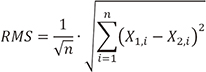
where X1,i is the measurement point of i in the reference data, X2,i is the measurement point of i in the measurement data, and n refers to the number of all points measured in each analysis.
The RMS value shows deviation from 0 for two different sets of data. Therefore, a low RMS value shows a high degree of 3D consistency in the overlapped data.28 In addition, 3D comparison was performed by using a color difference map, with a range of ± 100 µm (20 color segments) and a permissible tolerance of ± 10 µm (green). This makes it impossible to apply the error of less than 10 µm in the color difference map so that only the axial displacement according to the tightening torque can be seen. The error of less than 10 µm may indicate scan error and other errors, not axial displacement according to the tightening torque.
All data were analyzed by using the Statistical Package for the Social Sciences (version 23.0, IBM, Chicago, IL, USA) (α = .05). First, the normal distribution of data was investigated by using a Shapiro-Wilk test. Equality of variance was evaluated by using the Levene test for normal distribution. To determine the difference according to the type of implant-abutment connection, one-way analysis of variance (ANOVA) was conducted; as a post-test, differences among the groups were analyzed with Tukey's honest significant difference test. To compare overall displacement (3D) and vertical displacement (2D) of the abutment, the difference was also checked by using an independent t-test. Lastly, to examine the interaction effect of analysis methods (2D, 3D) and implant-abutment connection types (IS, IC, IZ, and ES), two-way ANOVA was conducted.
RESULTS
Two-dimensional and 3D analyses of the four types of abutments revealed significant differences according to the type of implant-abutment connection (P < .001) (Table 1). In addition, the vertical displacement value (2D) of the abutment was larger than the overall displacement value (3D), and significant differences were observed among the four types of abutments (P < .05) (Table 1). An interaction effect was observed between analysis methods (2D, 3D) and among the implant-abutment connection types (IS, IC, IZ, and ES) (P = .004) (Table 1).
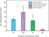
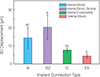
In 2D analysis, the IZ group (39.6 ± 10.9 µm) showed the most displacement in the vertical direction, whereas the ES group (2.6 ± 0.8 µm) showed the least displacement in the vertical direction (Fig. 5). Similarly, in 3D analysis, the IZ group (20.3 ± 6.8 µm) showed the most displacement in the vertical direction, whereas the ES group (4.4 ± 1 µm) showed the least displacement in the vertical direction (Fig. 6).
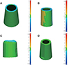
Fig. 7 shows that no 3D displacement of > 10 µm occurred in the ES group in the 3D analysis. In the IS and IC groups, displacement of > 10 µm occurred in the vertical direction, whereas no 3D displacement occurred in the horizontal direction on the axial plane of the abutment (Fig. 7). However, 3D displacement was noted in the horizontal direction on the axial plane of the abutment in the IZ group (20.3 ± 6.8 µm), demonstrating the greatest 3D displacement (Fig. 7).
DISCUSSION
There are several steps to making prosthetic implants, and axial displacement can occur at each stage.13161920 Among these steps, the greatest axial displacement is shown in the final implant prosthesis.13 Thus, in this study, axial displacements observed between hand tightening and screw tightening at the recommended torque were evaluated, according to the implant-abutment connection type.
The null hypothesis in this study was as follows: no size difference exists in the displacement of the four types of abutments in 2D and 3D analyses. However, the results of this study rejected the null hypothesis (P < .001) (Table 1). To compare 3D and 2D displacement of the abutment, overall displacement and vertical displacement were also assumed not to differ among the four types of abutments; this assumption was also rejected (P < .05) (Table 1).
In the study by Dailey et al.,10 Yilmaz et al.,11 Siadat et al.,21 and Kim et al.,24 which found the difference in axial displacement according to the type of implant-abutment connection was similar to the result of this study (INT > ETX). Because INT is less able to prevent vertical motion than EXT, vertical displacement occurs during screw tightening in INT.10111213 In this study, zirconia abutment (39.6 µm) showed greater axial displacement than titanium abutment (24.7 µm), but Gilbert et al.20 and Siadat et al.21 showed similar axial displacements in both materials. Although the axial displacement of the zirconia abutment has been large in this study, previous studies2021 have shown that the effect of the type of implant-abutment connection is greater than the material.
Several studies reported axial displacement during screw tightening. Yilmaz et al.11 identified a significant difference between hand tightening and the torque wrench method. Dailey10 measured axial displacement when using the recommended torque (25 N·cm) and a higher torque (45 N·cm); average axial displacement was 50 µm at the recommended torque, and 89 µm at the higher torque. Gilbert20 measured axial displacement in nine types of abutments and found that axial displacement was 3 – 12 µm in the horizontal direction and 3 – 5 µm in the vertical direction. Rebeeah27 measured axial displacement in two types of implant systems and found that the displacement did not exceed 14 µm. Several studies have reported varying displacement values because of differences in experimental conditions and measurement methods. In the present study, the difference in axial displacement between hand tightening (10 N·cm) and tightening at the recommended torque (30 N·cm) was measured; axial displacement occurred regardless of the type of implant-abutment connection. Of the four types of abutments, the INT zirconia ready-made abutment (39.6 ± 10.9 µm) exhibited the most displacement in the vertical direction, whereas the EXT ready-made abutment (2.6 ± 0.8 µm) exhibited the least displacement in the vertical direction. This result confirms a statistically significant difference based on the type of implant-abutment connection (INT, EXT) (P < .001) (Table 1). In addition, no significant differences were observed according to the manufacturing method (IS, IC) of the INT-type abutments, whereas a statistically significant difference was observed in relation to the material of the connection (P < .001) (Table 1).
Regarding the methods of measuring axial displacement, direct distance has mainly been measured by using a micrometer101319 or by imaging with a 3D digital image correlation technique.202627 In the present study, abutments and adjacent teeth were scanned by using a contact scanner to reduce errors in optical characteristics resulting from the material of the abutment,29 as well as from the experimenter's method of measurement. In accordance with ISO 12836, the contact scanner was operated at an ambient temperature of 23 ± 2℃; a single operator who was skilled in the use of the contact scanner conducted the scanning of each abutment. Furthermore, Geomagic 3D inspection software was used for 2D and 3D analyses, as recommended in ISO 12836.
Although the accuracy of all existing scanners is not entirely reliable, many studies report the use of an optical scanner with a reference model of approximately 10 µm for accuracy evaluation, and assess the accuracy of intraoral and extraoral scanners based on reference data.3031323334 Persson et al.35 compared accuracy and stability between a contact scanner and a laser scanner; a small error of < 10 µm was observed on the contact scanner. Moreover, the contact scanner was more accurate and stable, and could more efficiently reproduce the abutment margin, compared with the laser scanner. Dimitrova36 measured repeatability by imaging the abutment with an optical scanner (8.2 µm) and a contact-type scanner (6.9 µm), reporting excellent repeatability on contact scanners. Therefore, in this study, we measured displacement by using a contact-type scanner, which can acquire measurement points and obtain accurate coordinates by touching the probe directly, for scanning metal and zirconia abutment.
This study revealed differences in axial displacement, according to analysis method and type of implant-abutment connection; however, the effect of the prosthesis fabrication method and results in actual clinical practice were not investigated. Thus, in the future, it is necessary to produce prostheses for use in a specific type of implant-abutment connection and to conduct additional studies to evaluate their clinical effectiveness, such as the effect on actual occlusal contact with adjacent teeth.
CONCLUSION
In the limited results of this in vitro study, significant differences were observed in axial displacement according to the type and material of implant-abutment connection. Because this axial displacement may affect occlusal contact with adjacent teeth and implant prostheses, when choosing an abutment, axial displacement according to the type of connection must be considered. In addition, because axial displacement occurs regardless of INT and EXT during tightening at the recommended torque (30 N·cm), in a manner that contrasts with hand tightening (10 N·cm), it is advisable to tighten the screw at the manufacturers' recommended torque, rather than hand tightening to adjust the prosthesis.

 XML Download